Enpaix ETG15F1 User manual

ETG15F1
Coating Thickness Gauge
User's Manual
POLYGON INSTRUMENT LIMITED

Contents
1 Introduction 1
2 Structures 2
3 Operation 3
3.1 Preparation
3.2 Procedure
4 Setup 4
4.1 Measuring 4
4.1.1 Measuring mode 4
4.1.2 Limits of tolerance 5
4.1.3 Calibration curve 6
4.1.4 Test groups 6
4.2 Data 7
4.2.1 Browse 7
4.2.2 Print 7
4.2.3 Delete 8
4.2.4 Upload 8
4.3 System 9
4.3.1 Auto printing 9
4.3.2 Backlight 9
4.3.3 Beep 10
4.3.4 Power off 10
4.3.5 Time/Date 10
4.3.6 Unit 10
4.3.7 Default curve 11
4.3.8 Default system 11
5. Maintenance 12
5.1 Calibration 12
5.1.1 Zero-calibration 12
5.1.2 One-point 13
5.1.3 Two-points 14
5.2 Influence factors 15
5.3 Maintenance 16
Appendix
A-1 Packing List 17
A-2 Specifications 17
Warranty 18

1
1Introduction
Designed for non-destructive coating thickness measurement, it is
with built-in sensor, and works on the magnetic induction principle
and conforms to the following industrial norms and standards:
GB/T 4956, JB/T 8393, DIN EN ISO 2178, ASTM B499
The instrument is ideal for uncomplicated reliable on-site
applications. With its integrated measurement probe, measures the
thicknesses of coatings quickly and non-destructively utilizing the
magnetic induction.
It is suitable for non-destructive, quick and precise coating thickness
measurement. Easy to handle they are the ideal instrument for the
finishing industry, electroplating, ship and bridge building, aircraft
construction and the engineering and chemical industry.
1.1 Principle
The coating thickness gauge work on the magnetic-induction
principle for measuring the thickness of non-magnetic coatings(such
as paint, enamel, rubber, aluminium, chrome, cupper, tin etc.) on
magnetic metal substrates(ferrous bases and steel,also on alloyed
steel or on hardened magnetic steel, but not on austenitic steel or
weak magnetic steel).
When an alternating current electromagnet is brought near iron (or
the other magnetic metals) the number of magnetic flux lines
passing through the coil changes in proportion to the distance,
thereby causing a change in the voltage at the ends of the coil. This
change in voltage is determined from the current value and this is
used to compute the thickness of the coating.

2
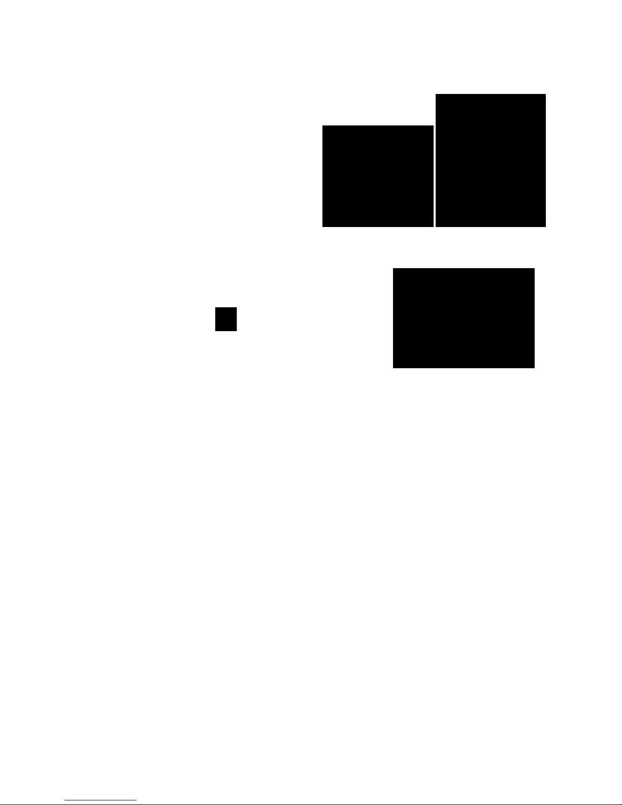
2 Description of structure
2.1 Gauge
The structure and appearance are shown as Fig.2-1 and Fig.2-2.
2.1 LCD display
battery compartment cover
Fig. 2-2
Fig. 2-1
Built-in Sensor
LCDUSBPower Button
Key
Up
Down
Zero/ESC
Menu
/Enter
Measured
number
Amount of test
group
Mean value
Measured value
Calibration curve number
Measure mode
Single Mode Continue Mode Fig.2-2
3
3 Operation
3.1 Preparation
1 Batteries
a) Slide and open the battery
compartment cover.
b) Insert the batteries into the
battery compartment. Respect
polarities as shown in Fig3-1. .
c) Close and fix the battery
compartment cover.
2 Switch on/ off
Press Power Button to turn on/ off..
Note:
If there are magnetic metals near the
probe at the moment of swatch on, the
gauge will display a alarm "Detect Error: Surroud Error!". Should
take gauge far from magnetic metals and wait few seconds it can
go normal.
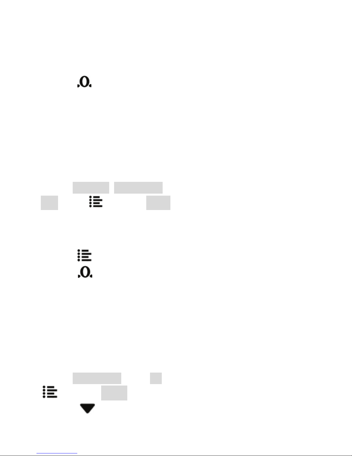
3.2 Measuring Procedure
a) Ready the test piece;
b) Switch on the gauge , "0.0μm/ mil" is displayed.
c) Calibrate the gauge if necessary.
d) Measurement:
Press gauge on the measured surface lightly and vertically. Or place
the gauge on measured surface of specimen directly.
After the buzzer, can lift the gauge and readout the measured value,
or measure the next point.
In order to more convenient and precise operation, may need to
make the necessary settings selection. Can be set by a menu.
Fig.3-1
Fig.3-2

4
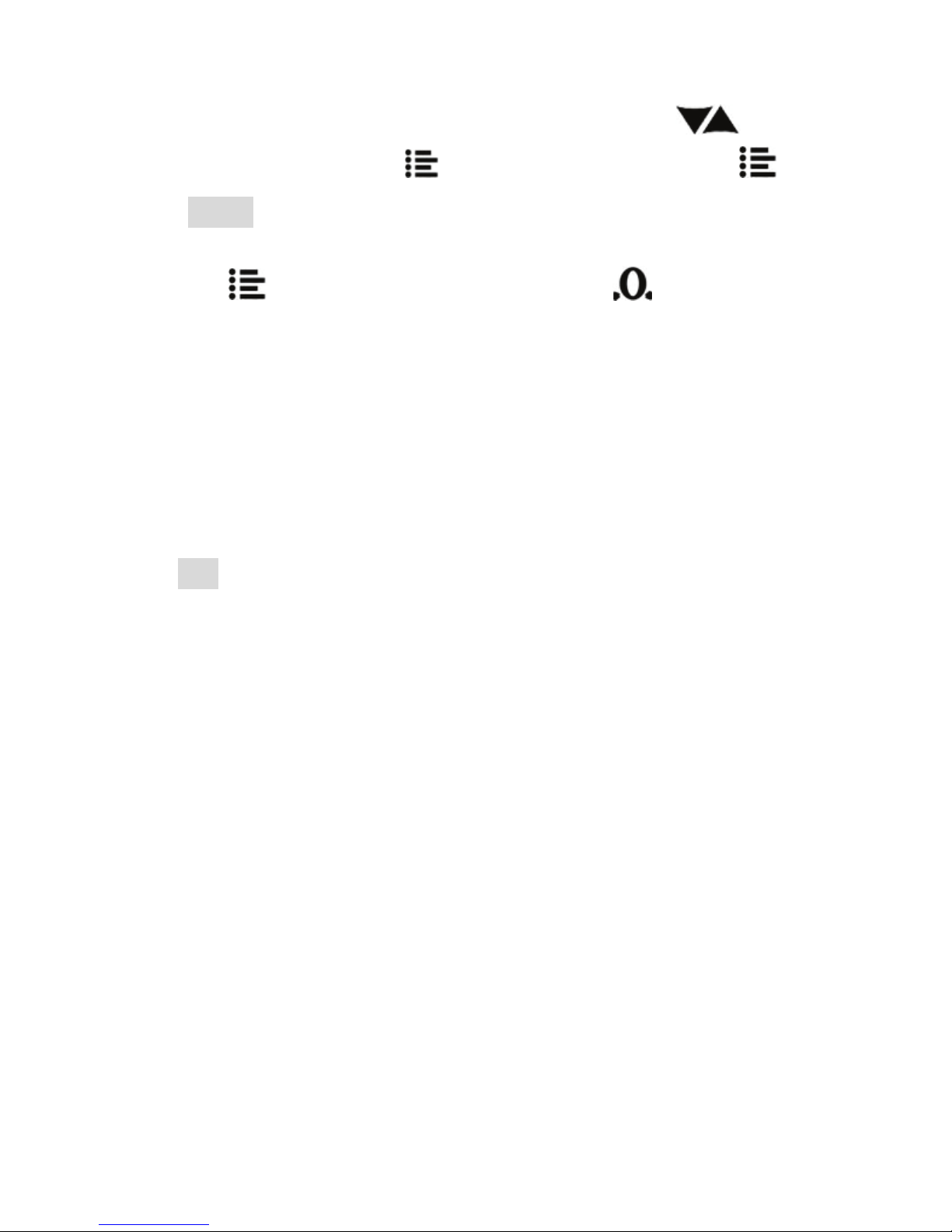
4 Setup
The gauge uses a menu for setting the parameters or the functions.
The structure of setup menu is shown in Fig 4-1.
In the measurement mode, press the "Menu" to enter the setup
menu. Press the "Up" or "Down" ("Up" or "Down"
the same below) can select a item, press "OK" to enter the
selected item.
In the menu settings, press to exit or return to the previous
menu. You can also press to exit setup and return to the
measurement mode.
In value input, Press to move digit, press to increase or
decrease value.
4.1 Measuring
4.1.1 Measuring mode
1) Single
In single mode the sensor of gauge touch the surface of specimen ,
measure one thickness value.
For measuring the another point , must lift up the gauge from
surface of specimen no less than 10cm and the interval should be
greater than 1 second.
2) Continue
Measurement and display continuously ,no need to lift the gauge

5
from the surface of specimen. Select the mode as Fig.4-2.
4.1.2 Limits
of tolerance
As the limits
of tolerance
are set, once
the
measured
value
exceeds
these limits
the gauge
will sound
alarm.
In b.Tolerance:
Can set to On (turn limit alarm on) or
Off(turn off limit alarm);
Or can select Upper Limit or Lower
Limit, to input the value.
Note:The upper limit should be greater
than the lower limit, otherwise this
alarm function is invalid.
Fig4-3
Fig.4-2

6
4.1.3 Calibration curve
The gauge can memory 6 calibration curves for difference kinds of
substrate.
Choice a appropriate calibration curve
can ensure precision of measurements.
if selected Form Data , Press the
certificated time and date will be
displayed.
if a curve which not certificated is
selected, "
--/--/---- --:-- "
will display.
4.1.4 Amount
of the test
groups
The gauge saves
the measured
data in test
groups, the
statistical
evaluation is in
one group too.
Each group can be 1 to 9 data.(Fig.4-5)
Fig.4-4
Fig.4-5

7
4.2 Data
In this item, data measured can be
browse, print and upload to PC.
4.2.1 Browse
In Single measurement mode, mean
value is saved when finished a group.
You can browse or print them.
Select data then presss , can
disply some information of selected
group.
4.2.2 Print
The gauge can connect to wireless printer for printing data in
memory.
First of all, turn on the printer, and make sure nearer than 3m
arround the gauge.
Fig.3-7
Fig.4-6
Calibrating
Curve
Mean value
Standard
Deviation
Amount of
measurements
Group number
Fig. 4-7

8
Then select data to print, "Current
group"," Select group" or "All".
if " Selected group " is selected, press
enter the group selection.
When selected, press the key , begin
to print.
4.2.3 Delete
With this function, you can delete
current measured value, current
measured group or all data in memory.
NOTE:
It couldn't restore again once you
deleted the data.
4.2.4 Upload
The data in memory can be uploaded to computer, you can use the
EDLS software to receive data. And manage, transform or analyse
these data with computer.
EDLS software must be set up in your computer (See manual of EDLS
Fig.4-8
Fig.4-9

9
for detail).
Connect the gauge and computer with
the cable (standard accessories) then
run EDLS in the computer.
Similarly, there are 3 options: Current
group , Selected group and All .
4.3 System
4.3.1 Auto
printing
If "Auto printing"
is turned on,
print measured
value of a group
as the measuring
end automatically.
When the
gauge is
restarted,
"Auto
Printing" is defaulted to "OFF".
4.3.2 Backlight
You can set Backlight to "Off","15s","30s"
and "On". Set to "Off", shut the backlight
down. Set to "On",the backlight will be lit
Fig.4-10
Fig.4-10
Fig.4-11

10
always.
"15s" means the backlight will be shutted down at 15 seconds after
no any operation.
Note: Set the backlight to "On" isn't recommended for battery
power save.
4.3.3 Beep
(Fig.4-12)
4.3.4
Power off
If the auto
power off is
set to "On"
power will be
shutted
down at 3 minutes after no any
operation.
4.3.5 Time/Date
(Fig.4-14)
4.3.6 Unit
(Fig.4-15)
Fig.4-12
Fig.4-13
Fig.4-14
Fig.4-15

11
4.3.7 Default curve
"Default curve" function may recall the
default calibration curve and delete all of
custom calibration curves.
On the other hand , the zero calibration
and one-point calibration and two-points
calibration are all deleted.
! So make sure you want to set to the
default curve.
4.3.8 Default system
Perform this function, all factory settings
are restored.
Calibration curves, measured value in
memory and settings by custom are all
deleted.
! So be careful to use this function.
Fig.4-16
Fig.4-17

12
5. Maintenance
5.1 Calibration
Due to mechanical wear in use, changes
in the test environment, with a different
calibration of substrate material will be
to the gauge to bring a certain error,
appropriate calibration can improve its
accuracy of measurement.
The gauge is designed with three levels
of calibration methods, zero-calibration
one-point calibration and two-point
calibration.
5.1.1 Zero-calibration
There are two ways for zero-calibration:
measuring calibration and menus
calibration.
1) Measuring zero calibration
Fig.5-1
Fig.5-2
13
a) In single mode, measuring on substrate directly and measured
value is "x.x μm".
b) Press , to zero the display to "0.0μm ".
Note:
i) If "x.x μm" is greater than 80μm, this calibration is invalid. Should
use menus calibration as following.
ii) Repeat the steps a) and b) for more
accuracy.
2) Menu zero calibration
a) Enter 1.Mesure- e.Calibration. select
Zero; press to display Acting;
b) Measuring on substrate directly. 4
or 5 times measurements should be
done for more accuracy.
C) Press for save zero calibration,
or press to discard calibration.
(Fig.5-2)
5.1.2 One-point calibration
Before performing the one-point
calibration, zero point must be
calibrated.
a) Enter e.Calibration, select 1st, press
to display 0000.0;
b) Press to enter values adjustment.
Fig.5-3
14
Adjust to mean value of standard thickness foil, press to
adjust the digital and press for move to next bit. press to
display Acting;
c) Measuring the standard thickness foil on substrate 4 or 5 times.
d) Press to confirm calibration, or press to discard
calibration.
5.1.3 Two-points calibration
After performing zero-calibration and
one-point calibration, you can do the
two-points calibration
Select 2nd, the following process is
exactly the same as one-point calibration.
(Fig.5-4)
Note: The standard foil used in
two-points calibration should be thicker
than the one used in one-point
calibration.
5.2 Influence factors
1 Magnetic properties of the substrate
The gauge used magnetic induction
method is affected by variations in the
magnetic properties of the basis metal. In order to higher measuring
accuracy, the substrate used in calibration adjustment should be the
Fig.5-4

15
same with the specimen as far as possible.
2 Basis-metal thickness
The gauge has a critical thickness of the basis-metal, greater than it
the measurement will independent of the thickness. It is about
0.5mm.
3 Roughness
Measurements are influenced by the surface topography of the basis
metal and coating. Surface roughness becomes significant when the
degree of roughness is greater than 10 % of the coating thickness,
causing increased scatter in measurements.
Therefore, on a rough or scratched surface, to make a greater
number of measurements at different positions to obtain an average
value that is representative of the mean coating thickness.
4 Residual magnetism
Residual magnetism in the basis metal affects the measurements
made by gauge that employ a stationary magnetic field. Its
influence on measurements made by gauge employing an alternating
magnetic field is much smaller.
5 Stray Magnetic Fields
5Strong stray magnetic fields produced by various types of electrical
equipment, can seriously interfere with the operation of the gauge.
6 Coating deform
For very soft coating, measuring probe will make deformation, so the
measurements of these specimens cannot be reliable, or may be
impossible.

16
5.3 Maintenance
1 Protect the gauge from dirt, dust, humidity, chemicals and
corrosive vapours. And do not let the gauge drop!
2 After use, please store the gauge in the protective case.
3 Avoid direct, strong sunlight and temperature-shocks as these can
have a negative influence on the measurement result.
4 The instrument housing is resistant to most chemical cleaners;
use a soft, moist cloth for cleaning.
5Exact measurements can only be taken with a clean probe.
Therefore the probe has to be checked and cleaned regularly so that
any paint residue and iron fragments can be removed.
6 When the batteries are low, “ ” will be displayed. The
batteries should be changed immediately (Note: 3*1.5V alkaline
batteries).
The calibrations and all kinds of settings are stored in a nonvolatile
memory, they will not be lost even if batteries go dead completely or
during the process of changing the batteries.
If the gauge is not to be used for an extended period of time, remove
batteries to avoid battery acid spoilage and the resultant destruction
of the electronics.
7The standard thickness foils are important in the calibration
procedure. If the foils are worn, broken, bent or damaged,
replacements are available from your dealer.
8If the gauge has a fault condition, please return it to the agent
who will assist you. If possible or return it to the factory for repair.

17
Appendix
A-1 Packing List
Name
Quantity
Coating thickness gauge 1
Standard thickness foil
5
Calibration Substrate 1
AAA1.5V Alkaline battery
3
USB Cable 1
Operation manual
1
A-2 Specifications
Test Method: Magnetic induction
Measuring Range: 0~1500mm (0 ~60mil)
Resolution: 0 ~ 999μm: 0.1μm, ≥1000μm: 1μm
Accuracy: up to100μm:±1.5μm; 100 ~ 1500μm: ≤1.5 %
Data Memory: up to 1500 readings.
Display: Graphic LCD with backlight
Power Supply: 1.5V*3 ( AAA batteries ).
Environment: 0 ~ 50°C
Dimension: 88 X 67 X 30 mm
Weight: 120 gr
Table of contents
Other Enpaix Measuring Instrument manuals


Popular Measuring Instrument manuals by other brands


Met One Instruments
Met One Instruments BAM-1020 Manual addendum

Pyxis
Pyxis ST-525SS user manual

Agilent Technologies
Agilent Technologies MXA Series Installation note

Endress+Hauser
Endress+Hauser Proline Promag W 800 technical information

Applent Instruments
Applent Instruments Anbai AT4808 user manual

TCS
TCS TCS 3000 installation manual