AEA Technology, Inc. LIBERATOR Series User manual

LIBERATOR SERIES
SWR & VNA Site Analyzer
Technology, Inc.
Testing Made Simple!
Operation Manual

Testing Made Simple
Proprietary Information
Reproduction, dissemination, or use of information contained herein for purposes other
than operation and/or maintenance is prohibited without the written authorization from AEA
Technology, Inc.
© 2019 by AEA Technology, Inc. All rights reserved. This document and all software or
rmware designed by AEA Technology, Inc. is copyrighted and may not be copied or altered
in any way without the written consent from AEA Technology, Inc.
The AEA Logos are trademarks of AEA Technology, Inc.
Acknowledgements:
Windows 7, Windows 10, and Power Point are registered trademarks of Microsoft Corp.
WD-40 is a registered trademark of WD-40 Company
409 cleaner is a registered trademark of Clorox Corporation
6050-3020 January, 2019

I
WARNING
DC Charging Port and A/C Adapter
Charging the Site Analyzer or operating while using the A/C or D/C adapters can create
external sparks during connection. Connecting or use of these power sources in an
explosive atmosphere is dangerous and should never be attempted. Always charge the
Site Analyzer away from any explosive atmosphere. Use ONLY internal battery power if the
presence of explosive fumes is a potential hazard.
Coax Test Ports
The presence of any voltage, from an applied source or static build-up on cables or
antennas, particularly vacant cables with no terminations or grounding, can cause an
ignition spark when they are connected to the Site Analyzer. Caution should be taken to
ensure cables are free of any voltages or static charge prior to connecting the instrument in
a potentially explosive atmosphere.
The SWR Site Analyzer instrument is not to be used in critical applications where failure of
the instrument or inaccuracies in data might cause personal injury or property damage. Use
in such applications is not recommended.
Operating Precautions
1. The Site Analyzer should not be used on outdoor antennas if the potential for
lightning exists. Wait until any lightning storm potential is well clear of your area
before attempting testing on outdoor antennas, particularly those mounted on
towers.
2. The Site Analyzer is designed for recharging NiMH AA cells only. Do NOT install
and attempt to charge LiION cells as overheating or re may result. The resulting
damage is not covered under warranty.
3. Alkaline cells may be used safely in the Site Analyzer, but when installed go to
the Battery Menu and change the Battery Type to ALKALINE or NONE to turn off
the charger. Attempting to charge alkaline or carbon cells may result in the cells
outgassing. The resulting damage is not covered under warranty.
4. The Site Analyzer, when in its Belt Case, is splash resistant and designed to work
for relatively long periods in rain depending on intensity. It is not designed to be
immersed in water. See Cleaning Instructions in the appendix.
5. The Test Port is limited to +22dBm input power. Power exceeding this level could
damage sensitive input components. Vacant antenna leads can build a static
charge and should be grounded to discharge them prior to connection.
The SWR Site Analyzer is designed to be safely operated in normal testing environments.
If you have any questions concerning the use of the Site Analyzer or other AEA Technology,
Inc. instruments please contact us at:
Tel: 1-800-258-7805 or +1-760-931-8979 or Fax: +1-760-931-8969
Email: [email protected]

II
Site Analyzer Literature Introduction
There are two literature items available for the SWR Site Analyzer:
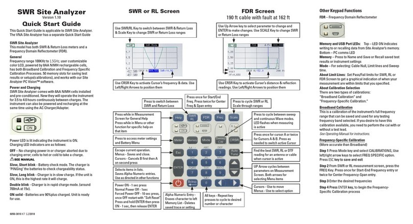
Quick Start Guide
is a laminated tri-fold held in the Belt Case’s inside pocket. This
provides a light-weight condensed guide to calibration, measurement functions and menus
Operator Manual
is this printed instructional guide which has three purposes:
1. Gives a concise description of the instrument, keypad, menus and
measurement screens.
2. Provides user instructions in more detail that the Quick Start Guide including
a section on Measurement Information and Helpful Tips.
3. Provides specifications, troubleshooting guides, and accessories lists.
Both these items are also available on the enclosed CD in PDF format ready for printing.
NOTES:
1. In addition to digital les of this literature the enclosed CD also contains Site
Analyzer PC Vision™ software and a training Power Point.
2. All these items and technical support is also available on our website:
www.aeatechnology.com

III
Table of Contents
1. Site Analyzer Description...........................................................................................1-1
Instrument Layout ...................................................................................................1-2
Keypad Operations.................................................................................................. 1-3
ON/OFF ...................................................................................................................1-3
Menu Keys..............................................................................................................1-4
Function Keys .........................................................................................................1-4
Help ........................................................................................................................1-4
SWR/RL...................................................................................................................1-4
FDR......................................................................................................................... 1-4
Freq ........................................................................................................................1-4
Scale.......................................................................................................................1-4
Sweep/CW ..............................................................................................................1-5
CRSR ......................................................................................................................1-5
ESC......................................................................................................................... 1-5
ENTER..................................................................................................................... 1-6
AutoTune................................................................................................................. 1-6
Arrow Keys ............................................................................................................. 1-6
Alpha-Numeric Keypad............................................................................................1-7
Battery Charging and Cell Replacement...................................................................1-8
2. Menus....................................................................................................................... 2-1
Menus Navigation ................................................................................................... 2-1
Meter Menu ............................................................................................................2-1
Color Scheme..................................................................................................2-1
Battery Menu................................................................................................... 2-2
Date/Time Menu..............................................................................................2-3
Mode Menu............................................................................................................. 2-3
Memory Menu......................................................................................................... 2-4
3. Measurement and Support Screens
General Information..................................................................................................3-1
Changing Measurement Parameters......................................................................... 3-1
SWR......................................................................................................................... 3-2
Return Loss.............................................................................................................. 3-3
Continuous Wave Mode ............................................................................................ 3-4
Cable Null/Calibration ............................................................................................... 3-4
FDR..........................................................................................................................3-6
FDR Velocity & Cable List.......................................................................................... 3-7
FDR Add a New Cable...............................................................................................3-8
FDR Distance, Center Frequency, & ∆F...................................................................... 3-9
Limit Lines SWR& Return Loss..................................................................................3-9
Limit lines setup....................................................................................................... 3-11
Limit Line and FDR ..................................................................................................3-11
4. Calibration, Measurement Information, and Helpful Tips
Site Analyzer Calibrations .........................................................................................4-1
Broadband Calibration Process ................................................................................. 4-2

Frequency Specic Calibration Process..................................................................... 4-3
SWR......................................................................................................................... 4-4
Return Loss.............................................................................................................. 4-5
SWR and Return Loss Measurement Steps ...............................................................4-6
FDR..........................................................................................................................4-7
FDR Measurement Steps .......................................................................................... 4-8
FDR Return Loss & k1/k2 Parameters....................................................................... 4-9
5. VNA Site Analyzer Measurements .............................................................................. 5-1
Mode Menu (VNA Dual Port Unit) ............................................................................. 5-1
VNA Screen............................................................................................................. 5-1
S21 Screen .............................................................................................................5-2
S21 Tracking........................................................................................................... 5-3
Spectrum Analyzer Screen ......................................................................................5-5
6. PC Vision Software ....................................................................................................6-1
Abstract ..................................................................................................................6-1
Installation .............................................................................................................. 6-1
Initial Setup............................................................................................................. 6-1
Display Screen........................................................................................................ 6-2
Basic Operation....................................................................................................... 6-4
Calibration .............................................................................................................. 6-5
Graphs in Detail ......................................................................................................6-7
Z-Plot...................................................................................................................... 6-8
Smith Chart (VNA) ................................................................................................... 6-9
Limit Lines ..............................................................................................................6-9
Naming Your Chart ..................................................................................................5-11
Saving Traces.......................................................................................................... 6-12
Frequency Domain Reector (FDR) .......................................................................... 6-13
Basic Operation (FDR) .............................................................................................6-14
Markers ..................................................................................................................6-16
Antenna Return Loss............................................................................................... 6-17
Calculating K1 and K2............................................................................................. 6-18
Other Tools..............................................................................................................6-19
Check Connection ...................................................................................................6-20
Battery Status ......................................................................................................... 6-21
Instrument File Management...................................................................................6-22
S21 Measurement Screen....................................................................................... 6-24
Spectrum Analyzer Screen ......................................................................................6-27
6. Warranty and Troubleshooting Guides........................................................................ 7-1
Instrument Troubleshooting Guide.............................................................................7-2
Battery/Charging Troubleshooting Guide ................................................................... 7-3
Appendixes
A. Specications....................................................................................................... A-1
B. Model’s Included and Optional Accessories...........................................................B-1
C. Cold Weather Operation........................................................................................C-1
IV

1-1
1. Site Analyzer Description
AEA’s Site Analyzer comes in two models, The SWR Site Analyzer Single port, and the
VNA Site Analyzer Dual port. Both instruments are rechargeable battery powered, SWR
and Return Loss meter with an FDR (Frequency Domain Reectometer). The VNA Model in
addition, features Vector Network Analysis (single and dual port) and Spectrum analysis.
The SWR’s primary use is for antenna systems testing. Secondary applications are for
testing cabling networks, electronic components, etc. Any application calling for a portable
SWR and Return Loss meter or an FDR from 100KHz to 1.5GHz. The VNA’s measurement
capabilities lends itself to in-depth magnitude and phase analysis of RF components such
as antennas, resonant cavities, lters and the like. Further, it’s spectrum analyzer function
is used in applications where RF carrier level and frequency measurements are required.
The SWR Site Analyzer is capable of performing the following testing:
Standing Wave Ratio (aka Voltage Standing Wave Ratio-VSWR)
Return Loss
Frequency Domain Reectometer (FDR) with measurements in either SWR or Return Loss
Additional features in the instrument are:
Cable Null – Removing the test lead or antenna cable’s measurements from the attached
antenna. Starts Broadband calibration.
Autotune – Find the best SWR or RL reading for an antenna in a selected frequency band.
Limit Lines – Set Pass/Fail limits for SWR, RL or FDR Screen to get a graphical indication
of when your measurements are within the limits that you have selected
BroadBand Calibration – Calibrate once for full band width 100KHz to 1.5GHz and it is
calibrated for all frequency ranges. This calibration provides a good level of
calibration accuracy and the convenience of not having to recalibrate for every
change in the frequency or span being tested.
Frequency Specic Calibration – This is the most accurate calibration, when precision
readings are important. This mode will automatically trigger the recalibration cycle
with any change in frequency or span. It is required for use with the FDR mode.
Memory – Saving and Recalling test results and settings (calibrations)
Rechargeable NiMH batteries (installed and preconditioned)
Full color QVGA Display. User can choose color scheme
Saves Current Operation and calibration data on power down
HELP includes: Measurement Screen navigation and setup guidance
Contact Sensitive Help – From any Menu item selected or highlighted, pressing Help will
provide guidance for that specic item or function being performed.
USB-2 Communications Port
SWR Site Analyzer PC Vision™ Software
In addition to all of the above, the VNA Site Analyzer is capable of the following tests:
Vector Network Analysis - Single port (S11) impedance analysis, measurements including
Impedance Magnitude, impedance angle, resistance, reactance, rho, theta.
Dual-Port (S21) Insertion Loss - Insertion loss (|S21|) and phase response analysis of any
passive two-port network. Scalar-only measurement also available, utilizing
the S21 Tracking feature.
Spectrum Analyzer - Classic amplitude-vs-frequency RF spectrum display.

1-2
Frequency
Domain
Reflectometer
Full color QVGA
backlit display
Frequency Band:
Set by Start/
Stop or Center
Frequency and
Span
Scale Range
adjust
Menus and
Function Keys
Cursor and Menu
Control Keys
Single N-Test
Port
USB-2 Mini B Jack
Quick SWR or RL
access from any
other mode
Both General
Help and Contact
Sensitive Help
LED Status
Indicators
Escape to exit
menus and
functions
ENTER to accept
alphanumeric
entries
Power ON/OFF
Input power/
charging jack
Not shown on the back is a desktop stand and battery compartment
For complete specifications refer to Appendix A.
For a complete list of accessories refer to Appendix B or visit our website at:
www.aeatechnology.com
Instrument Layout
SWR/RL Model Top End
VNA Model Top End
S11 N-Test Port
USB-2 Mini B Jack
Input power/
charging jack
S21 N-Test Port

1-3
Keypad Operations
The ON/OFF key is used to power the instrument on and off. There are different ON/
OFF sequences; Normal for starting with using the last settings at power down or
Soft Reset for starting with default settings. There are two different power down
sequences as described below the Power ON:
POWER ON – Press the ON/OFF key for one second.
A splash screen with AEA Technology’s logo and Version information will appear for
several seconds. It will then open to the testing being used at the time it was normally
or automatically powered down.
Keypad Power ON indication: LED lit
NORMAL POWER DOWN – From any Measurement screen, Press and hold the ON/
OFF key for one second only. Power Down sequence will start within one second later.
This power down sequence saves all the settings for resuming testing on the next
Normal Power On press. The BATTERY SAVER Auto-Power Down is a normal power
down and saves all the settings also.
HARD POWER DOWN – Press and hold the ON/OFF key for ten seconds. This forces
the Site Analyzer to shut down and should be used if:
A. The unit will not power down with a Normal Power Down (1 second hold of the key).
B. If the Site Analyzer is not performing correctly, menus or cursor keys do not work, or
the measurement screen does not appear correctly formatted.
NOTE: A Hard Power Down will NOT save the current settings as their data/data
corruption may be causing the firmware issue. If a Hard Power Down needs to be
executed the next power on should be the Soft Reset procedure to perform firmware
housekeeping and restore normal operation.
Soft Reset steps:
1. With the Site Analyzer OFF, Press and hold the ENTER key
2. Press and release the ON/OFF key to power the Site Analyzer ON.
3. After power comes on... (~1 second) release the ENTER key
4. Display will allow you to conrm reset to factory default settings.
5. When Measurement Screen appears you can recall a saved setting or set desired
settings

1-4
Menu Keys:
and
Refer to Section 2. Menus
Function Keys:
The Help key has two modes of operation; First, if no function keys are
active (CRSR, FREQ, etc.) and no menus are open, pressing Help will
open the help information for the displayed Measurement Screen. This
includes help with navigation in the screen and adjusting Frequency or Scale ranges.
Second, when a menu is open or a function key is active Context Sensitive Help
will open and provide instructions and options that address that particular open or
highlighted menu item or function.
Using the Help key is a great tool for getting started, refreshing your memory on how
things work.
Press the SWR/RL key from any other mode of operation to go directly
to one these measurement modes, or press as desired to alternate
between SWR and Return Loss modes. See section 3 Measurement
Screens for information on cycling modes, setup, and scales.
Press the FDR key to enter the Frequency Domain Reflectometer mode
of operation. See section 3 Measurement Screens for information on
cycling readings modes, setup, and scales.
Press the FREQ key to set frequency band of interest. There are two
types of setting screens for this operation:
A. Press once to enter START and END FREQUENCIES.
B. Press twice to enter CENTER FREQUENCY and SPAN.
Use the left/right arrow key to navigate digit positions, the alpha-numeric keypad to
enter values, and up/down arrow key to jump between upper and lower entries.
Press ENTER key to save changes and exit. If Broadband Calibration is selected it
will go directly back to the Measurement Screen. If Frequency Specific Calibration is
selected it will exit to the Calibration procedure.
The Scale key is used to cycle through preset vertical scales on the
measurement screens. SWR, RL and FDR have only one scale on the
left side of the plot. Repeated presses will present the next scale range
in the cycle. See Section 3 Measurement screens for more information on selecting
and changing Scales.

1-5
The Sweep/Continuous Wave key will switch the modes between
them. The LED indicator flashes when the instrument is sweeping the
selected band or transmitting the center frequency.
Sweep is the normal mode performing frequency sweeps from low to
high frequency selected and measurements appear in graphic plots.
Continuous Wave mode stops the Sweep mode and only emits a
continuous wave at the Center Frequency. This changes the graphic
plot to a list of tests showing digital value responses. The Continuous
Wave mode is useful when the antenna or other DUT is being tuned or adjusted. In
CW mode, measurements refresh at a faster rate than in Sweep mode.
See section 3 Measurement Screens for information on setup and cycling through the
readings list. To exit Sweep/CW, press SWR/RL or FDR to enter those modes.
The CRSR (Cursor) key is used to activate Cursor A or both A & B
Cursors with a second press of the key. Cursors are controlled as
follows:
A. Single cursor with data on screen. Cursor A LED lit. Use the left/
right arrow key to move the cursor. Readings will automatically
update to cursor’s position.
A & B. Press the CRSR key a second time to add the B cursor. Both A & B Cursor
LEDs will be lit. Dual cursors will display on screen with cursors’ differential reading
(CRSR ∆) below Cursor B. The active cursor will be the last CRSR summoned with the
CRSR key and the left/right arrow key will control that cursor. To alternate between
the Cursors A & B to change which cursor is active, press the CRSR key as needed.
Exit cursors – Press the ESC key once to exit Cursor B only or reduce to Cursor A only
and twice to exit both cursors.
The Escape key has the following uses:
A. Exits menus or backs up one menu level saving any changes.
B. Exits the cursors as described above.
C. In HELP mode, ESC closes the on-screen HELP window and returns
to either the Measurement Screen or the menu or function where it
was pressed to continue what you what operation you were doing
when HELP was pressed.
D. In Memory Save or Cable Null, Escape cancels the process prior to
completion.
E. See on-screen prompts about using ESC to complete the current
operation.

1-6
The ENTER key has the following uses:
A. In any measurement screen with a highlighted testing parameter, it
will either cycle through that parameter’s presets or exit to data entry
screen like FREQ for example.
B. Saves alpha-numeric entries and moves to the next step.
C. In Menus the ENTER key activates the highlighted Item.
The AutoTune key works slightly differently in SWR/RL and in FDR
mode, but in both cases it only functions with one or both cursors
enabled. In SWR and RL, pressing AutoTune will cause the selected
cursor to seek to the LOWEST point on the graph. In FDR mode, (again, with one
or both cursors enabled) AutoTune will cause the selected cursor to seek to the
HIGHEST point on the graph (not including the leftmost 2% of the display).
The up/down arrow key has the following uses:
A. In the menus it moves the highlight cursor to a desired item on
the vertical menu list. In Cable List and Memory Recall it moves
highlight up or down one cable type or Saved Test at a time.
B. In the measurement screens the UP arrow moves the highlight
between scales or other measurement parameters to make
changes to that parameter.
C. In the date/time menu it is used to cycle through the day, month,
year, or time settings.
The left/right arrow key has the following uses:
A. When in the measurement screen with cursors
enabled, it moves the active cursor left or right in
the plot.
B. When in any alpha-numeric settings (FREQ, date/
time, Memory save, etc.) it changes digit position for
character entries.
C. In the menus it changes the options (horizontal
menu) for highlighted items in the vertical menu.
NOTE: See section 3 for Menu Navigation, Screens’ Vertical and Horizontal menus.

1-7
The alpha-numeric keypad operates like those on smaller cell phones. Press a
selected key once for entering the number and repeat the key’s presses to cycle to the
character desired above that key. In an alpha entry screen the first press will present
the first alpha character above the number. Subsequent presses will cycle the alpha
characters and finally the number or use the Up or Down arrow to cycle through the
entire characters set
A. The squared U above the 1 key is a space.
B. There are more than just the 3 special characters shown above the 0 key.
Continued presses will cycle through them on screen for selection.
C. Bcksp = Backspace to erase the character to the left of the entry cursor.
D. Bcksp key in the Memory menu will erase the saved test result or setting.
CAUTION – There is NO UNDELETE. Once a test result or setup is erased it is
permanently deleted.

1-8
Battery Charging and Cell Replacement
General information
The Site Analyzer is powered by 8 NIMH AA cells that were installed and conditioned
at the factory as part of the manufacturing and testing process. New and fully charged
they will provide about 4 to 4.5 hours of continuous operation. Variables that affect
battery operating time are:
A. Backlight setting: Recommend use MED backlight. See Meter Menu to to select
backlight and change this setting. If HIGH backlight is used it will reduce operating
time.
B. Frequencies being tested: Higher frequencies consume more power and will reduce
battery operating time
C. Outside temperature: temperatures in the testing environment that are too hot or
too cold can affect battery operating time. This is also true during recharging. If
recharging in a very cold environment (below 32ºF or 0ºC recommend leave the
instrument in the Belt Case during charging to help the cells hold their temperature.
If recharging at room temperature (72ºF or 22ºC or above recommend removing the
Belt Case to help the cells stay cooler during recharging. If the charger detects the
cells are below 32ºF or 0ºC or they become too warm it will not attempt to charge
them. If the cells become too warm during charging the charger will automatically
shut off and the charging LED on the Keypad will turn off to indicate charging has
been aborted. This is not a normal situation, but can happen if the cells have been
in use for awhile and already warm from discharging and the charger is plugged
in immediately. There is NO re hazard with NIMH cells, but the cell’s chemistry
will not accept a charge above a certain temperature, so the process is aborted
and must be restarted by unplugging the charger’s AC or vehicle adapter, wait 30
seconds, and plug the adapter back in. This should restore the charging LED to lit or
blinking status. See the chart below for the Keypad’s Charging LED status.
Low Battery Warnings:
30 Minutes ERT: A warning window will open indicating the Estimated Run Time is at
30 minutes or less. This is a good time to save any test results and/or plug in the AC
adapter to continue testing and start a slow recharge.
Battery Icon: This icon will appear on the Measurement Screens to remind about the
limited battery operational time remaining.
Final warning: a message will appear on screen indicating 20 seconds or less
remaining battery operation time.
Auto-Shut-Down: The Site Analyzer will automatically power down below a set battery
voltage and will not power on again normally until either the unit is recharged, the AC
adapter is plugged in, or the battery cells are replaced with a fresh set of cells.
Battery Charging
The NIMH cells can be recharged using the AC adapter (included) or optional vehicle
adapter. Using the AC adapter is the preferred method and charges faster. The vehicle

1-9
adapter will charge or operate the Site Analyzer, but not both. A vehicle’s DC power
may vary from one vehicle to the other, but generally puts out about 12.5 to 14 volts
when the vehicle’s engine is running. The AC adapter’s input can accept 90-240VAC
50-60Hz, output is 15VDC at 1200mA. Full charge power is about 700mA @ 15VDC.
Charger LED Status
When unit if off the top LED will indicate the Charger’s status as follows:
OFF – No charging power in or charging aborted due to charging error; cells to warm
or cold to take a charge is one cause for abort. Others causes include: one or more
cells with incorrect polarity (installed reverse). Battery Menu has Alkaline cells
or None selected which turns off the charger. Dirty or corroded cell contacts and
depleted cells will also cause an abort condition. In all cases, an aborted charging
should be investigated by opening the battery compartment and search for any of the
above listed conditions and perform corrective action before attempting to charge the
cells again.
Slow, Short blink - Battery check mode. The charger is ‘PINGing’ the batteries to
check chargeability status. Battery Menu-CHARGER STAT: Prechg.
Slow, Long blink - Charger is in slow charge. If the unit is ON, this is the highest rate
it will charge. Battery Menu- CHARGER STAT: Slow Chg
Double blink: Charger is in rapid charge mode. (about 700mA at 15v). Battery Menu-
CHARGER STAT: Rapid.
ON solid – Batteries are 90%plus charged in Trickle Charge to top off. Unit is ready for
use. Battery Menu- CHARGER STAT: Trickle Chg.
To check the percent of battery charge turn the Site Analyzer ON, press Meter Menu
and note the Battery Menu line will display the percent of charge in lieu of Estimated
Run Time (ERT). If you enter the Battery Menu the Charger Status can be read in that
menu. NOTE: turning on the Site analyzer will reduce charging mode to slow charging
to prevent overheating the cells. The charging LED will go to Slow Long Blink mode
until the Site Analyzer is turned OFF again.
Alkaline Cell Use and Cell Replacement Instructions
Alkaline cells 1.5V AA size can be used to power the Site Analyzer. Normally this
would only be in the event the NIMH cells charge is too low to continue and there
is no access to AC power or vehicle power to continue testing. NOTE: if you have 8
new NIMH cells available they may require charging and charge conditioning prior to
being useful.

1-10
Battery Replacement Instructions
Preliminary: First ensure you have replacement cells on-hand, either 8 AA NIMH or 8
AA Alkaline cells. CAUTION: Mixing of cell types is highly inadvisable, and can lead to
faulty operation. Only use cells that are all of the same type and voltage.
Steps:
1. Remove the Belt Case, turn the Site Analyzer OFF and remove any external power and/or
antenna or other DUT and place the Site Analyzer face down on a clean padded surface.
2. Lift the tilt stand to reveal the two battery cover screws and use a number 1 Philips
screwdriver to remove them.
3. Lift the battery cover and stand to expose the cells. DO NOT REMOVE the RETAINING
BAND across the upper four cells.
4. Remove the lower cells and slide the upper cells under the retaining band down to a
vacant location to remove them. If installing AA alkaline cells as a temporary powering
measure, be sure to place the NIMH cells in a plastic bag and save them for re-
installation and re-charging. If the NIMH cells are being replaced due to end-of-life
cycle, please consult your local regulations concerning hazardous waste disposal. DO
NOT PLACE NIMH cells IN THE TRASH.
5. Inspect the battery case for any signs of outgassing (white or blue/green corrosion) on
the contacts or in the battery case. If any is found use a cotton tipped swab and alcohol
to clean the battery compartment and contacts thoroughly and dry before installing any
new cells. Instrument damage due to outgassing cells is NOT a manufacturer defect and
repair is NOT covered under our warranty.
6. Install the 8 replacement AA cells being sure to follow the battery polarity markings
stamped in the battery case. Remember they MUST all be the same type either alkaline,
or NIMH, DO NOT MIX CELL TYPES, Li-Ion batteries ARE NOT SUPPORTED.
7. Replace the battery cover and stand bale and ensure it seats back on the back case
correctly. NO force should be required for correct seating.
8. Re-install the two retaining screws. Tighten snuggly, but do not over tighten.
9. If alkaline cells were installed, Turn on the instrument ON and press the Meter Menu
key, select Battery Menu, then select Battery Type: and use the arrow keys to change
to Alkaline. This is important to turn OFF the Battery Charger and prevent accidentally
applying charging voltage to alkaline cells which could cause outgassing of the cells
and become hazardous.
10. If removing alkaline cells and re-installing NIMH cells, Turn ON the instrument and
press the Meter Menu key, select Battery Menu and, then select Battery Type: use the
left/right arrow key to change to NIMH to turn the Battery Charger back on. This will re-
activate the Battery Charging circuit. Lithium cells of any type use a different charging
process and are NOT to be used in the Site Analyzer at any time.
11. Conditioning New NIMH cells: When a new set of NIMH cells are installed they will need
to be conditioned before the Battery Menu can present valid Estimated Run Time (ERT).
Conditioning requires performing up to two deep discharging and full recharging cycles
(recommend charge overnight for full charge). The cells supplied by our production
facility where pre-conditioned at the factory, However, new cells purchased as
replacements have an unknown shelf time and condition and will require conditioning
so they charge and discharge in a consistent manner.

2-1
2. Menus
Menu Navigation
Menus contain two types of lists; vertical list is the one you can see all items available
and horizontal lists that only show the selected item’s options; mode or value. The
other horizontal selections are hidden. Navigation is accomplished as follows:
A. Use the UP/DOWN arrow keys to select (highlight) the desired item in the vertical
menu list
B. Then use the left/right arrow keys to change the highlighted item’s current setting
and scroll through the options. Some setting lists (horizontal menus) are as simple
as ON or OFF options, others are longer lists like the Color Schemes with 16 colors
to choose from for each item on the list.
C. Use the ENTER key as indicated to call a sub-menu of selections. Navigation in sub-
menus works the same.
D. When selections are completed, use the ESC key to save and exit the menu. Sub-
menus, if any, exit back to main menu and main menu exits back to measurement
screen.
The Meter Menu provides for control of the instrument itself. It has
direct action items that when highlighted and the left/right arrow key is
pressed changes the current setting to the next item in the horizontal
menu. Below is a list of items and their options:
BACKLIGHT: LO, MED, HI (recommend MED for best light with less
battery power consumption)
COLOR SCHEME: Press ENTER to open sub-menu
KEYPAD BEEP: ON or OFF
UNITS: FEET or METERS
BATTERY MENU: Press ENTER to open sub-menu
(also shows batteries’ % charging or ERT- Estimated Remaining
Time on battery power)
DATE/TIME: Press ENTER to open sub-menu
Press ENTER to exit and save changes in Meter Menu
Meter Menu’s Sub-Menus
COLOR SCHEME
TRACE A – 16 color list (use left/right arrow key to select)
TRACE B – 16 color list (use left/right arrow key to select)
CURSOR A – 16 color list (use left/right arrow key to select)
CURSOR B – 16 color list (use left/right arrow key to select)
MENU TEXT – 16 color list (use left/right arrow key to select)
BACKGROUND– 16 color list (use left/right arrow key to
select)
Note: Menu Text and Background are linked so the same color can NOT be used for
both. This ensures that the instruments menus will always be visible.

2-2
BATTERY MENU
BATTERY SAVER: ON or OFF
BATTERY TYPE: NONE, NI-MH, or ALKALINE
BATTERY MA-HR: 2300
EST. REMAINING TIME: 4.5HRS or
EST. Chg: 60.7% (only if charging) ERT: (if operating on battery power)
BATTERY STATUS: 11.5V, -479MA (voltage & pwr draw)
CHARGER STATUS: OFF, PRE Chg, Slow Chg, TRICKLE Chg
Notes: 1. First three items are only items user changeable as follows:
BATTERY SAVER – ON (will automatically power down in 5 minutes after last key
press). This is a normal power down and all modes and set-ups are saved and
recalled on powering back up. Not recommended when working with Site Analyzer
PC Vision software. Auto power downs will interrupt communications between the PC
and Site Analyzer.
BATTERY TYPE – NONE & ALKALINE (turns the battery charger system OFF). NIMH &
turns charger on.
BATTERY MA-HR – Can be changed if new rechargeable cells are installed with a
different MA-HR rating. This adjusts the charger and estimated run time (ERT).
BATTERY STATUS – Cells total voltage and either negative mA when discharging to
power the unit or positive mA to indicates the amount of charge being applied to the
cells. Fast charging (~700mA) can’t be seen as unit must be ON to view this screen.
Only Slow charging is used when unit is ON to avoid overheating the cells.
CHARGER STAT: Chgr Off – No input power or Battery Type: Alkaline or None is
selected, or charging has been aborted.
2. Abort Causes: Battery Check found errors: Alkaline cells detected, reversed polarity
on one or more cells (installation error), Depleted cells can’t be charged, cells too
cold or too hot to take a charge. The later can occur during the charging process
as the batteries become warm during charging. Recommend charging without the
Belt Case on to improve cooling and possibly moving to a cooler location or use a
fan to assist in cooling, before restarting the charging process. NOTE: If charging
overnight/unattended and the Charge LED is out when you return the charging
process is incomplete due to an abort condition. This requires finding the source/
cause and taking corrective action before restarting the charging cycle. First turn
the Site Analyzer on, press Meter Menu, then select and enter Battery Menu. If
BATT STATUS: is 10 or more volts, Site Analyzer will likely operate for 3 plus hours
before needing charging. If battery status is less, search for the condition causing
the abort, take corrective action, and continue the charging. If the Site Analyzer is
needed for immediate use, recommend replacing the NIMH cells with a fresh set of
8 AA alkaline cells to get 6-7 hours continuous performance.(See Section 1, Battery
Cell Replacement for instructions) Save the NIMH cells to re-install and attempt
recharging again. Try observing/checking of the charging process to see when the
charger aborts and troubleshoot the cause.

2-3
DATE/TIME MENU
Date: 17 MAY 2017
Time: 09 35
AM PM or MIL
Notes: Use LEFT/RIGHT arrow keys to highlight data to be changed. Use UP/DOWN
arrow keys to modify a data field.
Press ENTER to exit and save changes in Date/Time Menu. Exit will go up a level to
Meter Menu, press ESC to exit to Measurement Screen.
The Mode Menu contains a list of the following modes. Use UP/DOWN
arrow keys to select (highlight) desired mode and LEFT/RIGHT arrow
keys to select options in horizontal menu list or use ENTER to go to a
submenu when indicated.
MODE MENU (SWR Single port unit)
CALIBRATIONS: BROADBAND, FREQ SPECIFIC
CABLE NULL: <ENTER> (opens a submenu process)
SWEEP TIME: 1SEC, 500ms, 250ms, 125ms, 62ms, 31ms, 15ms, 8ms
SWEEP ON/OFF: ON, OFF
LIMIT LINES: ON, OFF
LIMIT SETTINGS: <ENTER> (opens a settings dialog box)
MODE MENU (VNA Dual port unit) see section 5
CALIBRATIONS: If BROADBAND is selected, that calibration, along with any test
lead and/or adapters desired is performed for the Site Analyzer’s entire frequency
range of 100KHz to 1.5GHz (See Section 4 for procedures). After that, any frequency
range can be selected without having to re-calibrate. This form of calibration will
provide moderate accuracy and the convenience of not having to recalibrate for
each frequency or bandwidth change. For the most accurate measurements select
“Frequency Specific”.
FREQUENCY SPECIFIC This calibration mode will require recalibration with any change
in frequency or bandwidth (Span). In this mode, the Site Analyzer will automatically
go to the calibration screen prompts when any frequency changes are entered. The
measurements, however, will be more accurate than using Broadband Calibration.
CABLE NULL: This is used to perform the Broadband calibration, and can be used with or
without a test lead and/or adapters attached. It will display a series of calibration screens
prompting the user to attach the Open, Short, and Load Terminators in turn. Press ENTER
for each one to complete the process. The Open prompt can use the open end of the
test lead, adapter or instrument’s N connector. Attaching an Open Terminator is optional,
although recommended for testing above 700MHz. Once this process is complete, the
calibration data is stored, and the instrument will be placed in BROADBAND calibration
mode. See Section 4 for more information on calibration steps.
For best results allow unit
to warm- up 5-10 minutes and use precision 3 way Open Load and Short.

2-4
SWEEP TIME: Sweep Time can be adjusted as desired for the best measurement
results. Fastest is 8mS to slowest 1 second. Select desired time using the Left/Right
Arrow keys.
SWEEP ON/OFF: Use the Left/Right Arrow keys to turn the Sweep ON or OFF. When
Sweep is on the frequency band selected is constantly being swept. The Sweep/CW
LED will blink indicating that Sweep is ON. Sweep ON can consume battery power
more rapidly. Turning Sweep off stops the sweep, turns off the Sweep/CW LED and
conserves battery power. This is a recommended mode when working at the PC with
Site Analyzer PC Vision software and not performing live bench testing. Not only
does it stop transmitting a frequency sweep, but saves battery power. It may also be
useful in some environments to stop transmitting a potentially interfering frequency
band when not connected for testing. Be sure to turn Sweep back ON before starting
calibration or testing.
LIMIT LINES: Pressing <ENTER> with this menu item selected, turns the limit lines ON
and OFF.
LIMIT SETTINGS: Pressing <ENTER> here will bring up the Limit Line Parameters
dialog box, where you can enter or edit the parameters for the limit lines. See page 26
for details
The Memory menu is for saving and recalling test results and settings
to/from the Site Analyzer’s internal memory.
MEMORY OPERATIONS
DATA SAVE – (Press ENTER to open a screen to enter the test result file name, then
save it in memory)
DATA RECALL – (Press ENTER to open a list of saved test results to select and recall)
SAVE SETTINGS – (Press ENTER to save the instruments current operating state. You
will be prompted to enter a name for the .SET file)
RECALL SETTINGS -- (Press ENTER to open a list of saved instrument setting files)
NOTE: When SAVE SETTINGS is invoked, the entire instrument state is saved- This
INCLUDES the current calibration, if FREQUENCY-SPECIFIC calibrations are in use!
These appear as files with the .SET extension.
When test results are recalled via DATA RECALL, the stored trace is displayed on
screen. Press ESC to return to the MEMORY menu.
When you are done with MEMORY operations, press ESC to exit Memory Menu.
This manual suits for next models
2
Table of contents
Other AEA Technology, Inc. Measuring Instrument manuals
Popular Measuring Instrument manuals by other brands

TestEquity
TestEquity ACL 350 Operation manual

LOVATO ELECTRIC
LOVATO ELECTRIC DME D301 MID manual

Honeywell
Honeywell SmartLine RMA800 user guide
Metrica
Metrica H4 manual
AquaMaster Tools
AquaMaster Tools E5O Pro user manual
Dwyer Instruments
Dwyer Instruments 477AV-000 Specifications-installation and operating instructions
