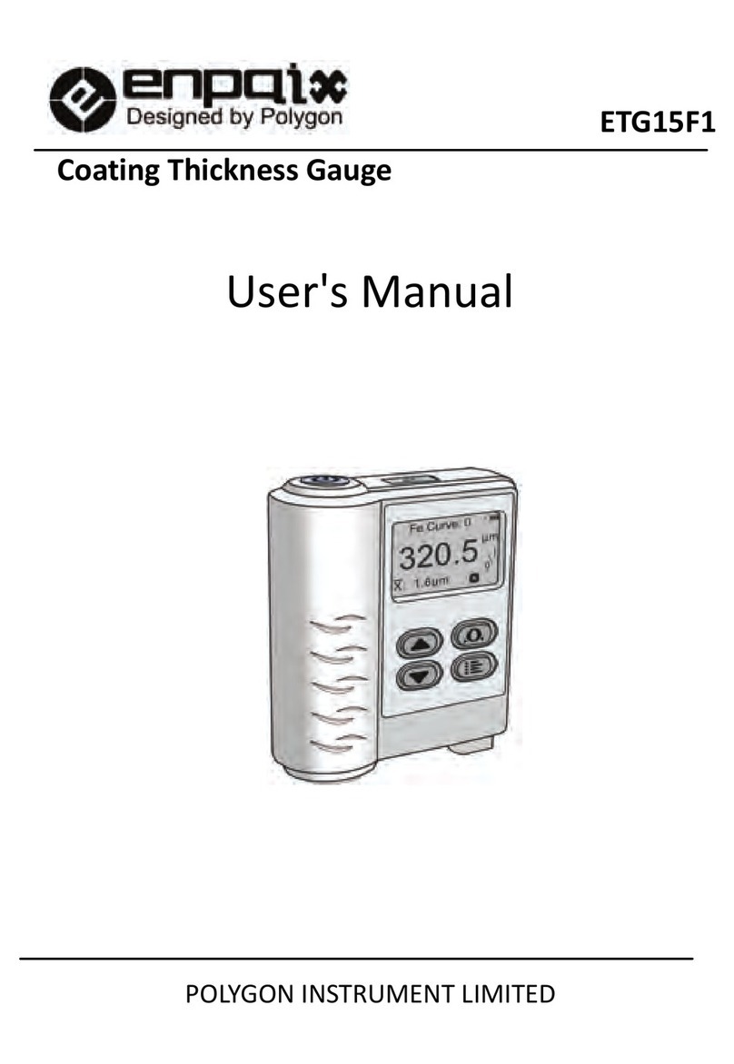
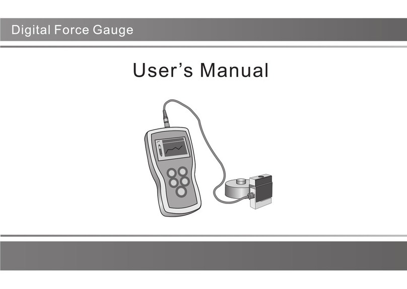
Enpaix ETTB series User manual

User ’s Manual
User ’s Manual
Digital Torque Tester

CONTENTS
1. Overview
1.1 Specifications 1
1.2 Models 1
1.3 keystroke 1
1.4 LCD Screen 2
2. Operation
2.1 Installation 3
2.2 Adapter Selection 3
2.2.1 Square Drive Adapter
2.2.2 Spring Adapter
2.3 Power on/off 3
2.4 Testing 3
2.4.1 Select Units
2.4.2 Select Test Mode
2.5 Zeroing 4
2.6 Storage/Print 4
3. Menus
3.1 Menus Structure 5
3.2 Measurement
3.2.1 Unit 5
3.2.2 Group
3.2.3Test Mode
3.3 Memory 6
3.3.1 Browse Data
3.3.2 Print Data
3.3.3 Delete Data
3.4 System Setting 7
3.4.1 Display Mode
3.4.2 Power Off
3.4.3 Back Light
3.4.4 Date/Time
3.4.5 Diagram Scale
3.4.6 Key Setting
3.4.8 Default Setting
4. Communication Ports
4.1 USB/Recharge 9
4.2 Multifunction Port 9
4.3 RS-232 9
5. Calibration 11
Appendix
A-1 Packing List 11
A-2 Dimensions 11
Warranty 12

1. Overview
1.1 Specifications
1.2 Models
There are four models in this series cap torque tester, the capacities and resolutions is on back cover.
1.3 keystroke
Power :Push for 2 seconds to power On or Off.
Store/Print :Through the system settings can be stored or print the current measured value; I n
number input, change to another digit or item.
Zeroing/Exit :During Measurement, Zeroing.; In Men us : Back o r.
Up/Mode : During Measurement: Changes Test Mode.
In Menus: Moves selection up or increases the value;
Menu/Enter: During Measurement: Enter the menus.
In Menus, Select or Enter.
Accuracy
± 0.3%
Selectable Units N.m, N.cm, kgf.cm, lbf.in , lbf.in Overload 120% of F.S.
Display Matrix LCD with Backlight Data Memory 1000 data
Measurement
Mode
Track, Peak , Preset, First Peak,Auto Peak Outputs
USB-B, Set point,
RS232
Power 3.6VDC Ni-MH rechargeable batteries Dimensions 197 x 180 x 83 mm
Charger/ Adaptor
Universal USB/BM char ger,
Input:110~240VAC
Weight 1.5 kg
Environment Operating: -10 to 40°C, 20 to 80% RH,Storage : -20 to +50°C , 5 to 95%RH
- 1 -

Down: During Measurement, Changes Test Mode.
1.4 LCD Screen
① Test mode
Track;Peak;
Preset;First Peak;
Auto Peak;. Auto First
Peak
② Analog bar and Direction
Icon
Indicates current position
in whole capacity. When the bar
enters the area enclosed by dotted line, means overload.
Clockwise(CW): ; Counterclockwise(CCW): .
③ Storage/print setting store; print.
④ time and Power
⑤ Torque value and Unit
⑥Datalist : Save the five-point measurements in the Peak and First Peak.
⑦Statistics: X :average; R:variance criterion.
⑧ Prompt: First Peak/Double Peak: Drop ratio
Preset: under lower limit ; between the limits ; over upper limit .
Data display Diagram Display
Fig 1-1
①
②
③
⑤
④
⑥
⑦
④
②
①
- 2 -

2. Operation
2.1 Installation
Please fix the torque tester on the workbench. See Appendix A-2 Installation dimensions.
2.2 Adapter Selection
2.2.1 Square Drive Adapter
Basic Adapter: □1/2” (12.5mm) socket. accordance with the appropriate scale to provide □1/4 "(6.3) or □
3/8" (10) square drive adapter.
2.2.2 Spring Adapter
An adapter that checks the torque value preset on an electric driver and absorbs inertia created by high
speed rotation,giving nearly the same torque effect as an actual tap screw.
2.3 Power on/off
Press for 2 seconds to power On or Off.
2.4 Testing
After completion of the test preparation, testing can be done.
2.4.1 Select Units
The torque gauge has a variety of measurement units, select the appropriate unit.
2.4.2 Select Test Mode
This series torque tester has 5 kinds of measurement test mode can choose. You can select it by press
under the measure interface, Or can change it in menus (See 3.2.3 Test Mode ).
Track: The real time measuring mode, under this mode, press the zero key the torque gauge will be cleared
(remove tare).
- 3 -

Peak: Peak readings will not change until a higher value is measured. Under this mode, press the zero
key the torque gauge will update the display immediately.
Preset:The tolerance limits can be set for GO/NG measurement also. If you set the alarm on and a valid limit,
The icon , , will be displayed for within limit, lower than lower limit or exceed upper limit.
First Peak: In this mode, the gauge can capture the first peak value of force, when the force value decreased
to reach the drop ratio. The drop ratio can be set in menus.
Auto Peak:In this mode, the peak capture will be updated in the time interval set in menus automatically
Auto First Peak:The first peak capture will be updated in the time interval set in menus automatically
2.5 Zeroing
Press to clear the torque gauge in track mode for removing the tare.
2.6 Storage/Print
Measured results can be stored in the torque gauge, so that you can review or print them later.
Under the measure interface, Press to save value measured, and the save icon will be displayed.
- 4 -

3. Menus
3.1 Menus Structure
3.2 Measurement
3.2.1
Unit(Fig.3-1)
3.2.2 Group
When several test samples
need to be measured, the
samples can be coded into
groups. The range is 01-99.
3.2.3 Test Mode
Test mode can be selected.
There are 4 kinds of mode:
Track, Peak , Auto Peak and
First Peak. See 2.4.3 Select
Test Mode also.
Fig.3-1
Fig.3-2
Fig.3-3
Measurement
Unit
Group
Tes t M o d e
Memory
Browse
Print All
Print Selected
Upload
Delete Selected
Delete All
System
Display Mode
Auto Power Off
Backlight
K e y To n e
Language
Date/Time
Diagram scale
Key Setting
Display Direction
Default Setting
Information
Calibration
- 5 -

① Preset
In the Tolerance menu, program
upper and lower limit for GO/NG Measurement.
The upper limit value must be greater than the lower limit, and
both limit value cannot be greater than 110% of the rated
capacity.
② First Peak
With 5% increase or decrease in the drop ratio of the adjustment
amount setting.
③Auto Peak
The Peak time should be set(Fig.3-6)
3.3 Memory
In this menu, browse the data in memory or delete it/them and
Print data.
3.3.1 Browse
Data
The greatest
number is the most recent data.
Move the cursor to a datum,push
can display some information for this datum.
Fig.3-4
Fig.3-5
Fig.3-6
Fig.3-7
Fig.3-8
- 6 -

3.3.2 Print data
You can print the data with "Print
All" or "Print Select".
3.3.3 Delete data
There are 2 methods to delete the
data.
Delete selected: Delete data in
number range selected.
Delete All.
Before delete data, a warning
window will pop up for further
confirmation.
3.4 System setting
3.4.1 Display Mode
There are two display modes:
Digital and Graphic.
3.4.2Power Off
The torque tester can turn the
power off automatically, some
time interval after no measuring
and no any operation. 5 minutes is default. You can change it for a longer or shorter
standby.
3.4.3 Back light
The torque tester can turn off backlight, some time interval after no measuring and no
Fig.3-9
Fig.3-10
Fig.3-11
Fig.3-12
Fig.3-13
Fig.3-14
- 7 -

any operation. You can select this time or turn it on or off always.
3.4.4 Date /Time
3.4.5 Diagram scale
The ordinate range selection When printing the chart. There are 4 kinds of type:
20%,50%,100% of F.S.
3.4.6 Key Set ting
The key is a multifunction key.
It can be set as "store the current display value(Storage)" or "print the recent data
(Print)"."Storage" is default.
3.4.7Default Setting
When the artificial error, and do
not know how to restore, the
gauge can be restored to factory
settings. it will lose that some
information set by customs.
Restoring to Default Setting, the
password must be enter and a
prompt must be confirmed.
Password:1 2 3.
Fig.3-15
Fig.3-16
Fig.3-17
Fig.3-18
Fig.3-19
- 8 -

4. Communication Ports
There are two kinds of port for recharging and communicating with
PC and the other equipment.
4.1 USB/Recharge
Use this port, you
can connect the
gauge to the
computer for
transform data to PC in accordance with
USB2.0.
Or recharging with connecting the recharger.
4.2 Multifunction port
The assignment of pins is shown in Table 4-1.
4.3 RS-232
USB/ Recharge
Table 4-1 Pin Assignment
Pin
#Description
1
RS232
Tx
2
Rx
3
Gnd
4 Setpoint Output B
5
6
Common
7
Setpoint Output A
8
Multif unc tionPort USB/Recharge
Fig.4-1
RS232 specifications
Data word length 8 bit
Stop bit
1 bit
Parity
None
Baud rate 9600,19200,
38400
Hardware Flow Control
None
- 9 -

5. Calibration
Because of the sensor material performance or the influence of
external factors, there may be errors in a certain range after a
period of time use. Should send the torque gauge to a
specialized testing organization for calibration.
If you have some standard force weights or the other
standard load and some test stand, you may calibrate it also.
① Mount the torque gauge.
② Remove the tare by use of the key .
③ Enter Calibration interface, as Fig 5-1. (Password: 1 2
3)
④Load a standard force.Now the value in standard
input area is just equal to the current measured value.Wait a
moment for the force stability.
⑤ Press and to input the standard force value.
⑥ Press to enter the next calibration. Press can interrupt the calibration.
NOTE:
❶Set the unit of force to the unit used in calibration previously (as shown in 3.2.1 Unit)
❷Ensure that the tare weight of attachment has been remove before calibration.
❸You can do any point or points calibration from 1 to 5 point, we recommend 5 points calibration.
Fig 5-1
- 10 -

Appendix
A-1 Packing List A-2 Dimensions( mm)
Tester
USB Cable
Recharge
User's Manual
Square Drive
- 11 -
Table of contents
Other Enpaix Measuring Instrument manuals
Popular Measuring Instrument manuals by other brands
Keysight Technologies
Keysight Technologies E4980A Configuration guide

FujiFilm
FujiFilm FUJI DRI-CHEM IMMUNO AU CARTRIDGE vf-SAA Instructions for use

Milwaukee
Milwaukee MC310 user manual

Keysight
Keysight N2140A quick start guide
Vortex
Vortex BLUEONE BWO 155ZM Original operating instructions
Preferred
Preferred JC-13D2 Installation & operation instructions
Rohde & Schwarz
Rohde & Schwarz R&S SMCVB-K160 user manual
CruzPro
CruzPro FU60 user manual

GF Signet
GF Signet Signet 2580 FlowtraMag operating instructions

Canon
Canon RA-532H Quick manual
AFRISO
AFRISO DIM 20 instruction manual
Precision Digital Corporation
Precision Digital Corporation PD8-6262 instruction manual
