EnPro EHR-S 250 User manual
Models:
EHR-S 250
EHR-S 500
EHR-S 1000
Technical Manual of Enpro
Energy Recovery Ventilator
Attention
Please read this manual carefully before using the equipment
Ening d.o.o.

Safety Considerations------------------------------------------------------------3,4
Unit Specifications--------------------------------------------------------------- 5
Dimensioned Drawings------------------------------------------------------------6
Installation Considerations----------------------------------------------------7,8,9
Electrical Installation--------------------------------------------------------------10
Wiring Diagrams------------------------------------------------------------------11
Commissioning Information------------------------------------------------------12
Controller Instruction-------------------------------------------------------13 to 21
Dial switch------------------------------------------------------------------------22
Maintenance ----------------------------------------------------------------------23
Contents
2

Please read the following safety instructions before installation. And ensure that the unit is installed
correctly.
Please observe all instruction in order to avoid any injury or damage to equipment or property.
Safety attentions
The following symbols indicate potential levels of caution.
Situations with a risk or death or
serious injure. Situations with a risk of injury or
equipment/property damage.
The following symbols indicate compliance which must be observed
Not allowed or Stop Must follow or obliged
Installation to be carried out by qualified
person, End Users must not install, move or
re-install this equipment by themselves
An anti-bird net or similar device should be
installed to outside vents. Ensure there are
no obstructions to or in the ducts
Installation engineers must follow this man-
ual strictly. Improper action can create a
health hazard and reduce efficiency of the
unit
Fresh air vent must be far enough away
from any flue gas discharge or areas where
hazardous vapors are present
Unit must be installed strictly following this
manual and mounted to a weight bearing
surface for the weight of the unit
Electric engineering must follow national
regulations and the manual, use special ca-
bles. Less capacity cables and improper en-
gineering can cause electric shock or fire.
During maintenance or repair, the unit and
circuit breaker must be switched off. Other-
wise electric shock could occur.
Ground wire cannot be connected to gas
pipe, water pipe, lighting rod or telephone
line etc. Incorrect grounding can cause
electric shock.
Power cable and wires must be installed by
a qualified electrical engineer. Improper
connection can cause over heating. Fire and
loss of efficiency.
To avoid condensation, insulation should be
fitted to fresh air ducts. Other ducting may
also require insulation depending on dew
point conditions.
Insulation between the metal ducting and
wall penetration must be installed if the
ducting penetrates metal wall cladding, to
avoid risk of electric shock or current leak-
age.
The cover of wiring box must be pressed
down and closed to avoid dust and dirt en-
tering. Excess dust and dirt can cause over-
heating of terminals and result in fire or
electric shock.
Use only approved installation hardware
and accessories. Failure to observe can re-
sult in fire risk, electric shock and equip-
ment failure
Where the unit is positioned, at high level in
a hot humid situation. Please ensure suffi-
cient ventilation is available
The outdoor ducts must be installed facing
downwards to avoid rain water entering.
Improper installation can cause water leak-
age.
Correctly sized MCB must be fitted to the
unit suitable earth leakage protection
should also be installed to avoid risk of elec-
tric shock or fire.
3
Safety Considerations

Safety Considerations
Do not install the unit in an extremely hu-
mid conditions, as it may result in electric
shock and pose a fire risk.
Do not use the units as the primary kitchen
extract grease and fatty deposits can block
the heat exchanger, filter and pose a fire
risk.
Don not install the unit in areas there any
poisonous or caustic gases are present.
Do not install the unit near open flame as it
may result in over heating and pose a fire
risk
Acidic or alkali environments can cause
poisoning or a fire
Rated supply voltage must be maintained,
otherwise this may cause fire.
4
Safety Considerations
This appliance can be used by children aged from 8 years and above and persons with reduced
physical, sensory or mental capabilities or lack of experience and knowledge if they have been
given supervision or instruction concerning use of the appliance in a safe way and understand
the hazards involved.
Children shall not play with the appliance. Cleaning and user maintenance shall not be
made by children without supervision.
Means for disconnection must be incorpo-
rated in the fixed wiring in accordance with
the wiring rules.
Prior to cleaning or other maintenance, the
appliance must be disconnected from the
supply mains.

5
Specifications
Model EHR-S 250 EHR-S 500 EHR-S 1000
Performance
Airflow (m3/h) 200/250/250 400/500/500 840/1000/1000
Airflow (l/s) 55/69/69 111/138/138 233/277/277
Enth. Eff (%) Heating 73/65/65 75/67/67 72/62/62
Cooling 71/62/62 72/63/63 68/60/60
Temp. Eff (%) 81/73/73 81/76/76 80/76/76
Noise Db(A) 27/34/34.5 29/35/39 36/42/44
Power Supply 220V/1Ph/50Hz
Input Power (W) 117 200 690
Power Cable 2x1.5mm2
Control Cable 2x0.5mm2
Control
Standard Yes (7-Day Time-clock)
(BMS)
Modbus Yes
Fan Type AC Fan Motors
Fan Speeds (Supply) 3 Speeds Individual Control
Fan Speeds (Exhaust) 3 Speeds Individual Control
Summer Bypass Yes (Automatic with adjustable range)
Defrost Yes (Automatic with adjustable range)
CO2 Control Optional controller available (On / Off control with adjustable range)
Fan Boost Contacts Yes (3x available connections to Volt-Free Contacts: Closed = Boost to High Speed)
Fire Shutdown Yes (1x available connection to Volt-Free Contact: Closed = Shutdown)
Weight (Kg) 25 36 79
Size (LxWxH) 744x599x270 824x904x270 1129x1216x388
Duct Size 150 200 250
EHR-S 250 and EHR-S 500 Models
6
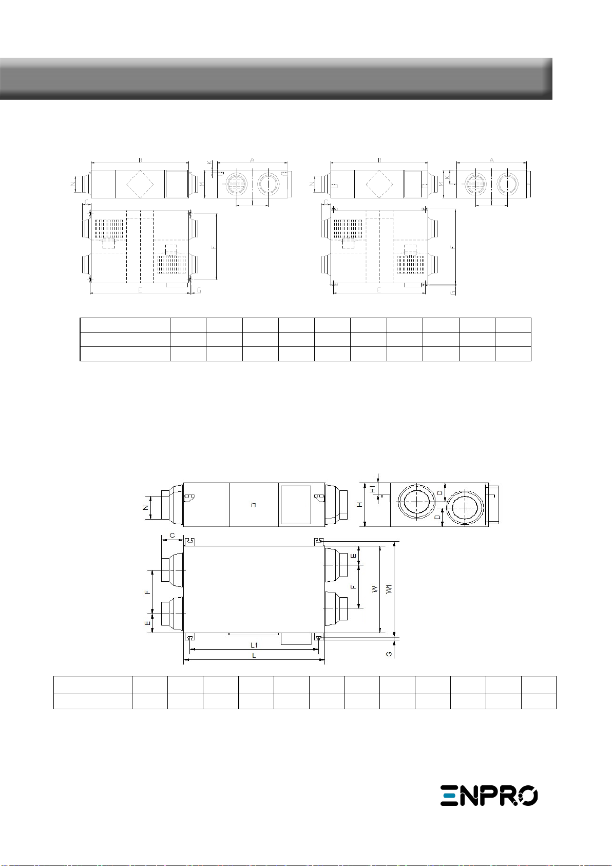
Dimensioned Drawings
Electric
Box
EA
OA
EA
OA SA
RA RA
SA
Electric
Box
Model ABCEFGIKMN
EHR-S 250 599 744 100 675 657 19 315 111 270 Φ144
EHR-S 500 904 824 107 754 960 19 500 111 270 φ194
Electric
box
E
A
O
A
S
A
R
A
Model LL1 WW1 HH1 NCDEFG
EHR-S 1000 1129 1060 1216 1273 388 171 Φ242 86 147 152 621 21
EHR-S 1000 Model

Installation Considerations
Protect the unit to avoid dust or other obstructions entering the unit and accessories during installation,
or whilst in storage on site. Service ports should be installed to allow access for filter maintenance.
7
Installation Considerations
Model AInner ceiling
height B
EHR-S 250 599 320
EHR-S 500 904 320
EHR-S 1000 1216 450
EA
RA
OA
SERVICE PORT
EA
SA RA
OA
SERVICE PORT
SA
天花板吊装螺杆
(Φ10-Φ12)
螺母
垫圈
吊装部件
垫圈
螺母
Suspending screw pole
Nut
Gasket
Suspending Part
Gasket
Nut
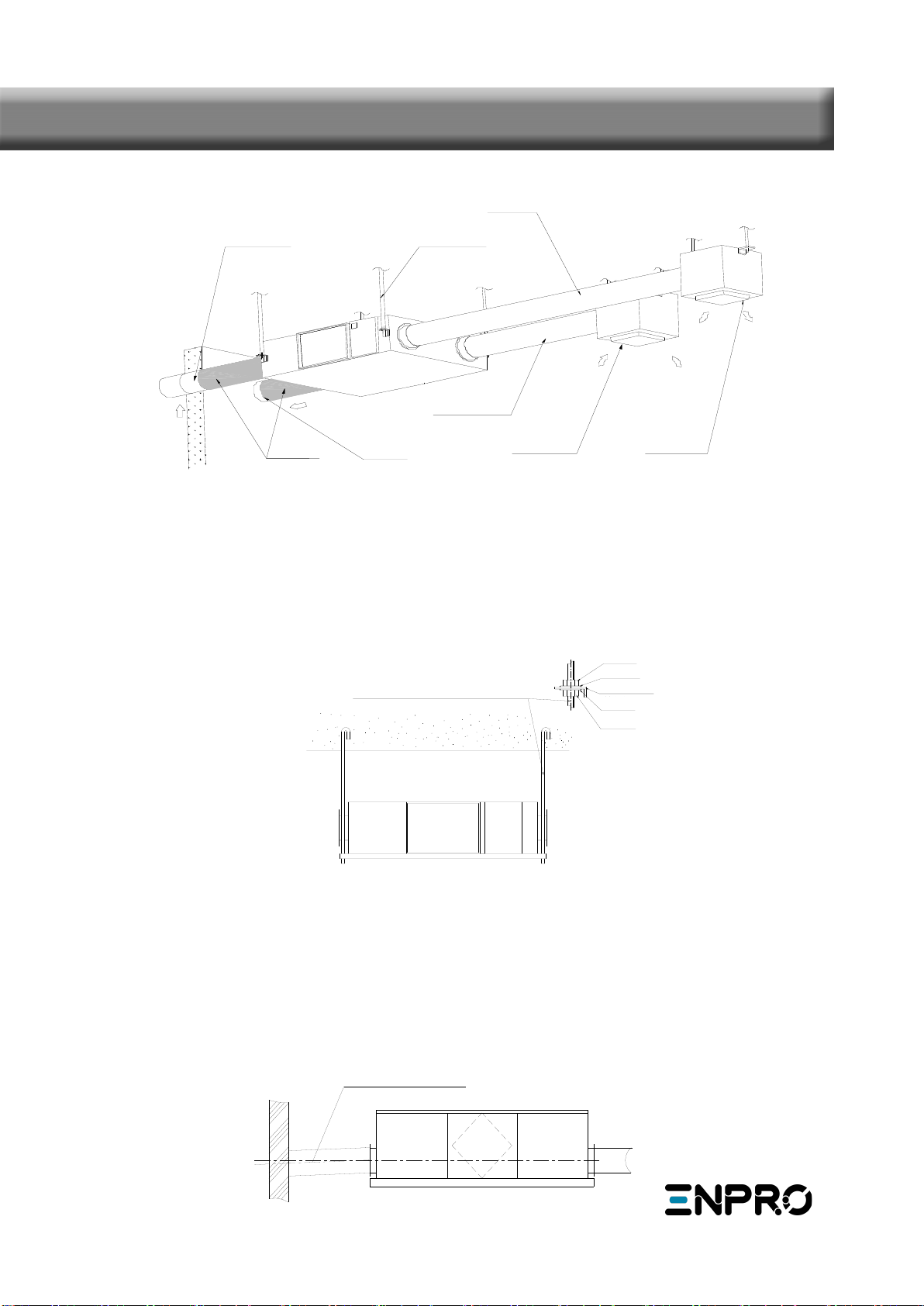
Installation Diagram
Fresh Air In
Exhaust Air Out
Outside Fresh Air Duct
Insulation Discharge Duct
Suspending Pole
Fresh Air Duct
Exhaust Duct
Return Air Supply Air
Return Air
Supply Air
Physical Installation
1.Installer to prepare suitable threaded hangers with adjustable nuts and gaskets.
2.Install as shown by the image above. Installation must be level and securely fastened.
3.Failure to observe proper fixing could result in injury, equipment damage and excessive vibration.
Uneven installation will also effect damper operation.
Notes for reverse installation of the unit
4.Reverse labeling shows the unit is upside down.
Ducting
1. Connection of unit vents and ducts should be taped or sealed to prevent air leakage, and should com-
ply to relevant guidelines and regulations.
2. The two outdoor vents should face downward toward the outside to prevent any rain water ingress.
(angle 1/100 1/50).
3. Insulation must be with the two ducts outside to prevent condensation.
Material: glass cotton, Thickness: 25mm
Installation Considerations
8
坡度1/100-1/50
Gradient1/100-1/50
1. Be sure the ceiling height is no less than the Figures in above table B column.
2. Unit must not be installed close to boiler flues.
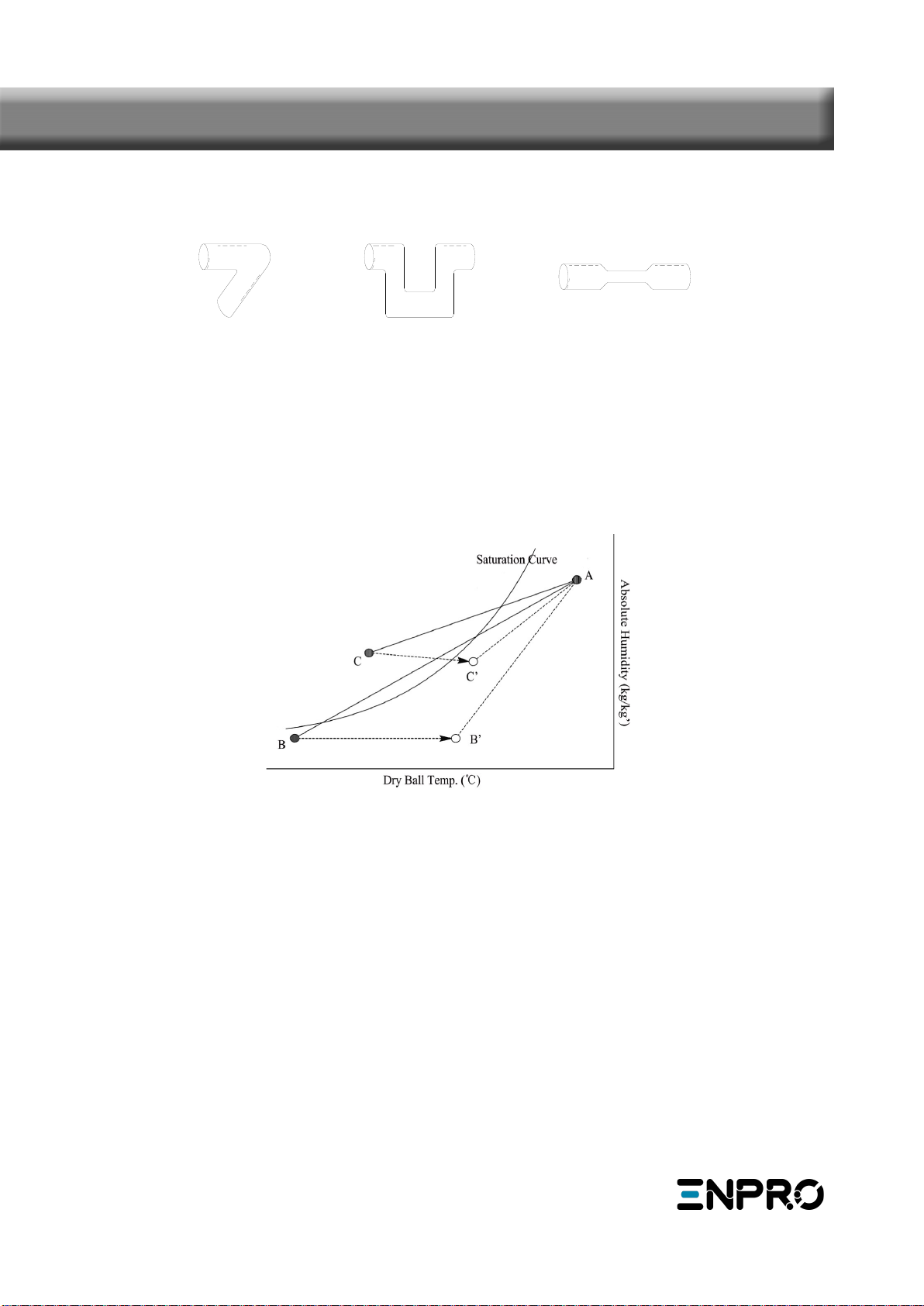
3. Following phenomenon should be avoided in the ducting installation.
Serve bends Multiple reducers/ crimped duct
Multiple direction changes
4. Exessive use of flex-duct and long flex-duct runs should be avoided.
5. Fire dampers must be fitted as per national and local fire regulations.
6. Unit must not be exposed to ambient temperature above 40℃ and should not face an open fire.
7. Take action to avoid dew and frost.
As shown by drawing below, unit will produce dew or frost when saturation curve is formed from A to C.
Use pre-heater to ensure conditions are kept to right of the curve (B to B',to move C to C) to prevent
condensation or frost formation.
8. To avoid the outdoor exhaust air cycling back to indoor, the distance between the two vents installed
on the outside wall should be over 1000mm.
9.If heater is equipped to the unit, operation of heater should be synchronous with the unit, so that the
heater starts to work only when unit starts.
10.Duct muffler may be considered if user wants indoor noise to be minimized.
Installation Considerations
9

Power must be isolated during installation and before maintenance to avoid injury by electric shock. The
specifications of cables must strictly match the requirements, otherwise it may cause performance fail-
ure and danger of electric shock or fire.
Power supply is AC220V/50HZ/1 Phase. Open the cover of electrical box, connect the 4 wires to the ter-
minals and connect the cable of the control panel to the board according to the wiring diagram, and join
the control panel to the cable.
We do not accept any liability for any problems caused by the user’s self and non-authorized re-
engineering to the electrical and control systems.
10
Electrical Installation
Model Capacitor Power Supply Control Panel Model
EHR-S 250 1.5μF450V AC
220-240V/1Ph/50Hz
Touch screen
controller
EHR-S 500 3.5μF450V AC
EHR-S 1000 10μF450V AC
Model Spec. of power supply
cable
Spec. of normal controller
cable
EHR-S 250
4×1.5mm2 4×0.5mm2
EHR-S 500
EHR-S 1000
EHR-S 250 to EHR-S 1000
11
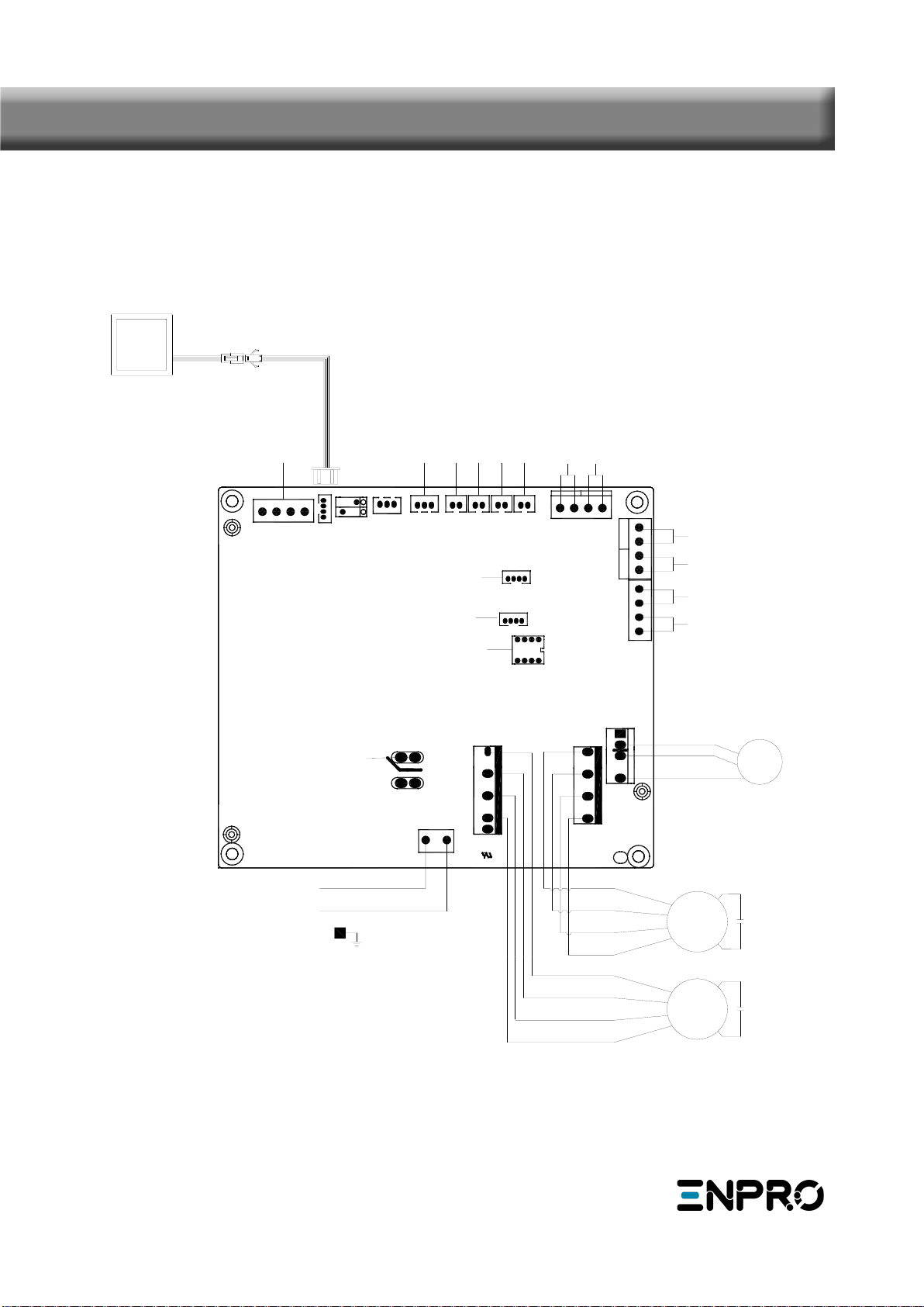
Wiring Diagrams
94V0
PORT 4
PORT 3
PORT 2
PORT 1
L N
12V AGND
B
AN2
AN1 AN3 AN4
COMM1S1
S2
*
*
C02
*
CN10
CN8
CN12
CN11
CN9
CM-DM
CN-SAFM
CN-EAFM
LD4
LD3
CN13
CN3 CN7 CN6 CN4
CN5
CN2
SW4
CN27
L
N
Connect with
heater or relay
By-pass switch
Fire alarm signal input
Fault signal output
Running signal output
External swith
SA temp.
FR(EA) temp.
OA temp.
RA temp.
CO2 sensor
Reserve switch
RS485 ports
Humidity sensor
Dial switch
M1
M2
Yellow
Blue
White
Black
Yellow
Blue
White
Black
Control panel
Joint of control panel and cable
Standard length: 5m
Exhaust fan
Supply fan
Connect the tin end of cable
to the port, no sequence
Voltage:220V-1ph-50/60Hz
PE
WIFI
WIFI ports
GM
Yellow
White
Black
By-pass

Check that all cable sizes, circuit breakers and wire connections are correct before following below com-
missioning steps:
1. Press button ON/OFF to turn on/off the ventilator.
2. Match the correct fan speed displayed on touch screen controller to ERV.
Under Off status, press MODE button for 6 seconds to enter parameters setting and at this
time the parameter number is shown in the middle of the screen, press button SET to switch to
parameter No. 23 (refer to parameters list in comming page) then press MODE button shortly to
enter the parameter setting, default value “0” flesh in the middle of panel, press UP and DWON
buttons to change the value be “1 (3 speeds control)” then press SET button again to confirm
setting.
3. Then check the mode and fan speed switch. Press button MODE shortly to switch to OA, RA, SA or EA
mode, check whether the temperature of the corresponding mode is correct. Under SA or RA mode,
Press UP and DOWN button to switch the fan speed, check if the airflow is adjusted corresponding to
H(high) speed, M(middle) speed and L(low) speed .
4. Check the operation of bypass. The default opening temperature of bypass is 19-21C (adjustable),
press button MODE button to check the temperature of OA. If the present OA temperature is among
19-21C, then bypass will open automatically. If the OA temperature is not within 19-21C, say 18C,
then under OFF status press MODE button more than 6 seconds to enter the parameter setting.
Press SET button to switch to parameter number 02, default value 19 flashes shown at the top right
corner, Then press MODE button shortly to enter setting, by pressing UP and DOWN buttons and set
the value to be “X”, “X” should be less than 18℃(present OA temperature), then press SET again to
confirm. with the same way to set parameter number 03 value to be “Y”, if “X”<OA temperature
<“X+Y”. then bypass will open automatically, after bypass open, user can adjust the values under
parameters 2 and 3 to make OA<“X” or OA>“X+Y”, then bypass will close automatically, please pay
attention that bypass open/closed will be around 1 minute delayed.
Note:
In ON status, press MODE button for 6 seconds to check the indoor air quality (if IAQ sensor connected).
In OFF status, press MODE button for 6 seconds to adjust the parameters in the Modbus.
Loose or incorrect wiring connection can
cause explosion or fire when the unit starts
to work. Use only rated power voltage.
Don’t put fingers or objects into vents of
fresh air or exhaust air supply. Injury may
be caused by the rotation of the impeller.
Don’t install, move or re-install the unit by
yourself. Improper action may cause unit
instability, electric shock or fire.
Don’t change, disassemble or repair the
unit by yourself. Improper action may cause
electric shock or fire.
Running the unit continuously in an abnormal
status may cause failure, electric shock or
fire.
Switch off the power and breaker when you
clean the exchanger.
Don’t site intake supply vent in hot and hu-
mid
conditions , as it may cause failure, current
leakage or fire.
Don’t put any burner directly facing the
fresh air discharge, otherwise it may cause
an insufficient burning.
Isolate power during extended off periods
Isolate power and take care when cleaning
unit. (Risk of electric shock)
Observe guidelines and regulations relating
to incomplete combustion when use is asso-
ciated with fuel burning appliances.
Clean the filter regularly. A blocked filter may
result in poor indoor air quality.
Commissioning
12
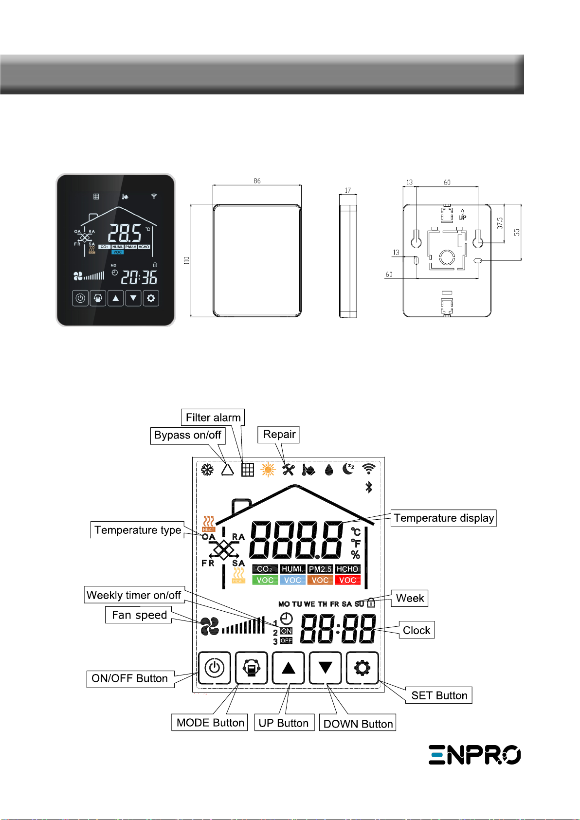
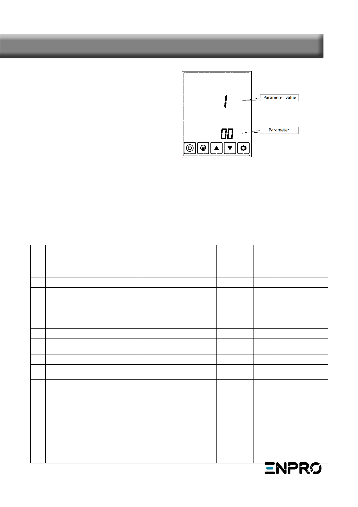
Display screen and Buttons
Control Panel
Touch Screen Intelligent Controller
The intelligent controller is surface mounted and comes with a touch screen LCD display screen.
Standard connection cable is 5 meters, in case of a longer cable is needed, then please use the shielded
cable, to avoid the signal interference which may lead to communication error.
13
Operation Instructions
1. ON/OFF: press ON/OFF button once for starting; twice for closing. In ON status, backlit LCD display
lights up, in OFF status, backlit LCD display off, without operation for 6 seconds, backlit LCD display
off too. By pressing ON/OFF button for around 6seconds can lock and unlock the controller.
SA temperature
FR temperature
2. Mode switch: press MODE button to choose display the RA-OA-FR(EA)- SA Setting-CO2 status or Hu-
midity control status.
OFF state
RA temperature OA temperature
ON state
Lock state Unlock state
Touch Screen Intelligent Controller
14

Remark:
1) Under SA setting mode, after connecting the electrical heater to the PCB (LD3 and LD4) and change
parameter 01 to value 1, users can set the supply air temperature by pressing up and down button. The
setting temperature range is 10-25oC.
A) 0℃<setting temperature minus SA temperature<5 ℃,1st stage heater on, 2nd stage heater off
B) Setting temperature minus SA temperature >5℃,1st and 2nd stage heater on
2) The CO2 symbol appears when the CO2 sensor is connected. ERV runs at boost speed when CO2
concentration higher than setting value.
3) The humidity symbol appears when the “temperature and humidity sensor” is connected. ERV runs at
boost speed when humidity higher than setting value.
Under “humidity control” mode, users can set the setting humidity by pressing up and down button. The
setting range is 45% ~ 90%. And the Dial switch SW4-3 on the PCB should be switched ON to switch
from CO2 control function to humidity control function.
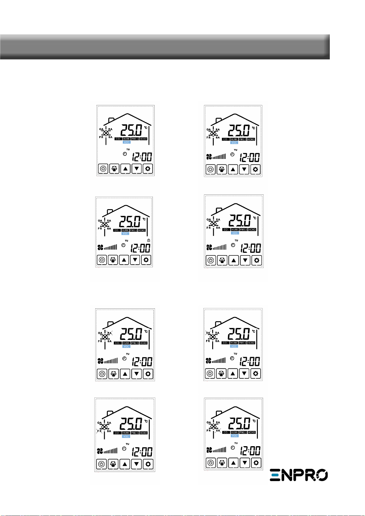
3. Air volume setting: Under SA or RA temperature interface. Users can set the return air volume in
“RA” status, and set the supply air volume in “SA” status by pressing up and down button. Totally 10
speeds control.
Speed 3 Speed 5 Speed 10
SA temperature setting CO2 concentration
Humidity control
Touch Screen Intelligent Controller
15
5. Bypass setting: when bypass is on, the triangle bypass symbol appears, when bypass is off, the sym-
bol disappears, please refer to page 15 commissioning part for the detailed setting introduction.
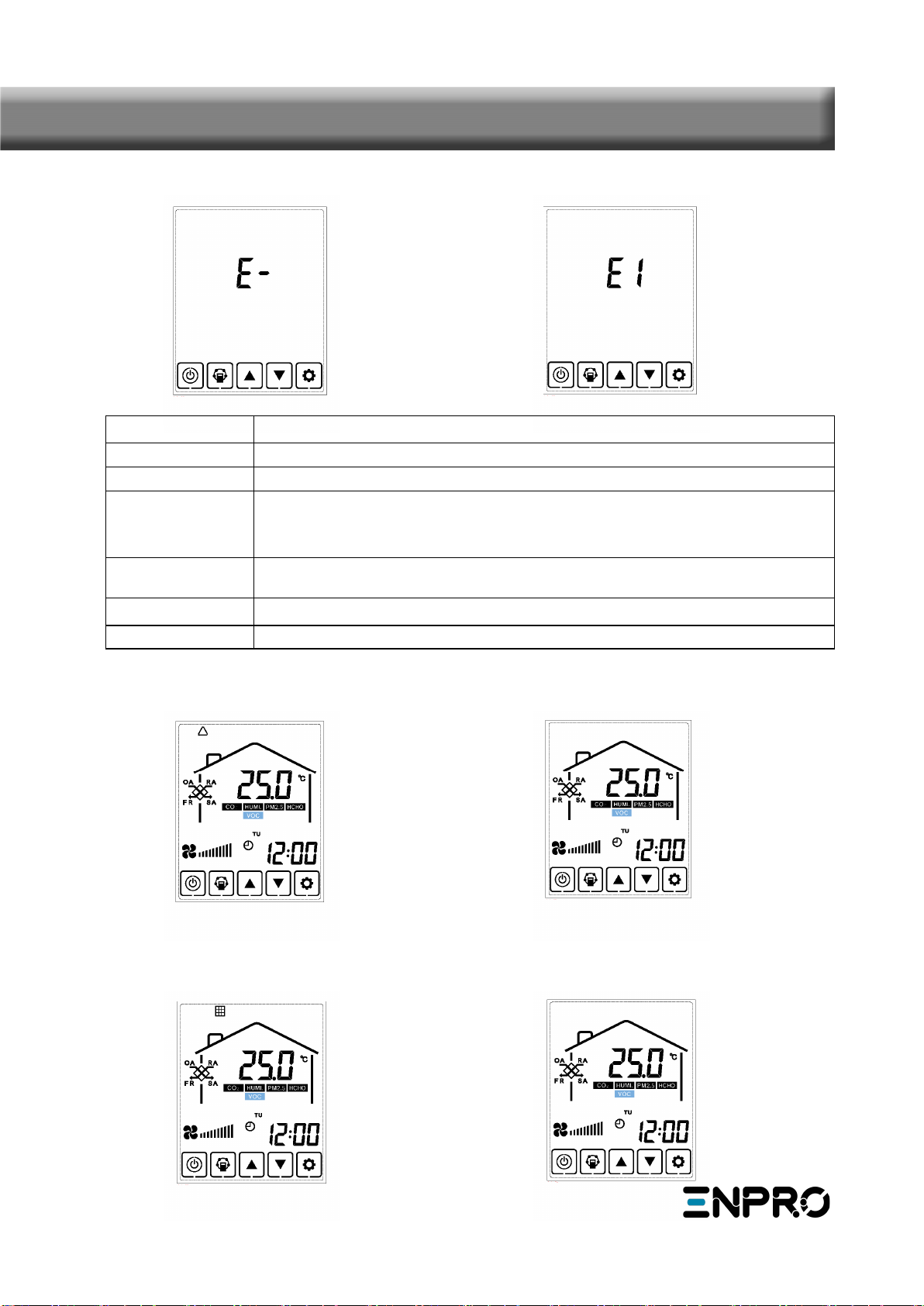
4. Error code checking: under the main interface, press the SET button for short, user can check the
error code of ventilator, refer to below table.
6. Filter alarm: When running time of ventilator is over the setting filter alarm time, the filter alarm
symbol flashes to remind user clean/replace the air filters. After filters being cleaned/replaced, please
sweep the filter alarm by setting parameter Number 24, value 1.
16
Code Error
E1 Fresh air temperature sensor error
E2 EEPROM error
E3 If SW4-3 on the PCB is OFF, the return air temperature sensor error. If SW4-3
on the PCB is ON, the humidity sensor is abnormal.
E4 Exhaust air temperature sensor error (defrosting temperature error)
E5 Communication error
E6 Reserved
Touch Screen Intelligent Controller
No Error Error alarm
Bypass on Bypass off
Filter alarm on Filter alarm off
17
Touch Screen Controller Instructions
7. Parameters setting: Under OFF status, keep pressing the MODE button for 6 seconds, after buzzing to
enter the parameter setting interface.
After entering the parameter setting interface, press SET button shortly to change the parameter num-
ber, every pressing will make parameter value +1 (until number 25 then repeat again). After choosing
the correct parameter number, press Mode button for short, parameter value flashes in the middle of
panel, at this time to change the value by UP and DOWN buttons. After parameters setting then press
SET button to save.
Attention:
1) After parameters setting, system need around 15 seconds to record, during this period power should
not be off.
2) Please refer to below valid parameters table to set the suitable parameters according to different re-
quests.
No
.
Contents Range Default Unit Record Position
00 Power to auto restart 0-11Main control
01 Electrical heater available 0-10Main control
02 Bypass opening temperature X 5-30 19 ℃Main control
03 Bypass opening temperature
range Y
2-15 3℃Main control
04 Defrosting interval 15-99 30 Minute Main control
05 Defrosting entering tempera-
ture
-9-5- 1 ℃Main control
06 Defrosting duration time 2-20 10 Minute Main control
07 CO2 sensor function value 28-C8(392-1960PPM) 66
(1000PPM)
Main control
08 ModBus/ERV ID address 1-16 1Main control
21 Air speed mode selection (valid
for DC motors only)
0-70Main control
22 Reserved 0-40Main control
23 Fan speed display selection 0: 2 speed (H L)
1: 3 speed (H M L)
2: 10 speed (DC fan)
0
24 Multiple function setting 0: Reserved
1: Filter alarm clearance
2: Weekly timer clearance
0
25 Filter alarm timer 0: 45 days
1: 60 days
2: 90 days
3: 180 days
Main control

Instruction of Parameter Settings
1) Parameter 00 refers to power to auto restart
0: Invalid, 1: Valid
2) Parameter 01 refers to Supply air electrical heater function
0: Not available 1:Available
When connecting with supply air electrical heater, user should choose 1 to activate the electrical heater,
and under the SA temperature setting interface (see page 17), the SA temperature can be set by press-
ing up and down button. The setting temperature range is 10-25℃.
3) Parameter 02-03 refers to automatic bypass function
The bypass is opened on the condition that the outdoor temperature is equal or higher than X
(parameter 02)and less than X+Y (parameter 03). Bypass is closed on other conditions.
4) Parameter 04-06 refers to automatic defrost function
When EA side of heat exchanger temperature lower than –1℃(defrosting entering temperature, param-
eter 05) and last for 1 minute, and the interval of defrosting is longer than 30 minutes (parameter 04),
the exhaust fan will run at high speed automatically for defrosting, and supply fan will stop, until EA
side temperature higher than defrosting entering temperature +15℃ for 1 minute, or the defrosting
time is longer than 10 minutes (parameter 06).
5) Parameter 07 refers to CO2 concentration control function (optional)
After connecting the optional CO2 sensor, the CO2 symbol will display on the screen. If CO2 concentra-
tion is higher than setting value, then ERV runs at high speeds automatically, after CO2 concentration is
lower than setting value, then ERV returns back to the previous status (stand by, low speed or medium
speed), if the ERV is already in high speed when CO2 concentration higher than setting value, then ERV
keeps the high speed running.
6) Parameter 08 refers to the central control function to identify the address of ERV.
7) Parameter 23 refers to the fan speed display, for the ERV with AC motor, user should change value
from 0 to 1 for three speed control.
8) Parameter 24 refers to clear filter alarm and weekly timer setting.
9) Parameter 25 refers to set the filter alarm timer.
18
Touch Screen Controller Instructions

19
Touch Screen Controller Instructions
Time setting Week setting
Weekly timer on Weekly timer off
A. Time setting: under time setting interface, press SET button for short, at this time “hour” flashes,
press UP and DOWN button to change “hour”. After setting “hour”, press MODE button for short to
switch to “minute” setting, at this time “minute” flashes, press Up and Down button to change “minute”.
After time setting, press SET button to save and return to the main interface.
Hour setting Minute setting
8. Time setting
Keep pressing the SET button for 6 seconds, after buzzing to enter the time setting interface. Under this
interface, press the MODE button shortly, then can switch from time setting, day setting, weekly timer
on and weekly timer off setting.

23
B. Day setting: under day setting interface, press SET button for short to begin the day setting, by
pressing UP and DOWN buttons to select the correct day, after this finished, press SET button to save
and return to the main interface.
Timer on valid Timer on invalid
Day setting
Touch Screen Controller Instructions
Period 1 timer on Period 2 timer on
Timer on hour setting Timer on minute setting
C. Weekly timer on setting: under weekly timer on setting interface, press SET button to begin the tim-
er on setting, press SET button time after time to select Monday period 1 to Sunday period 2 (namely
Monday period 1 to Sunday period 2).
After selecting the day, press ON/OFF button to confirm timer on is valid/invalid.
When timer on is valid, press MODE button to enter “hour” setting, by pressing UP and DOWN button to
set “hour”. After “hour” setting, press MODE button to enter “minute” setting. After “minute” setting,
press SET button to save and switch to the next day timer on setting, and repeat the above steps to set
all days and periods timer on. After setting all the time on, press SET button to save the data.
This manual suits for next models
2
Table of contents
Popular Fan manuals by other brands


System air
System air Fantech FLEX VHR 150R Installation and operation manual

Arneg
Arneg HPF series Direction for Installation and Use

Sterling
Sterling F-29A instructions

LUNOR
LUNOR VA-40 operating manual

LUCCI Air
LUCCI Air Altitude Eco Led Installation instructions manual

Bionaire
Bionaire BWF0910AR Instruction leaflet


