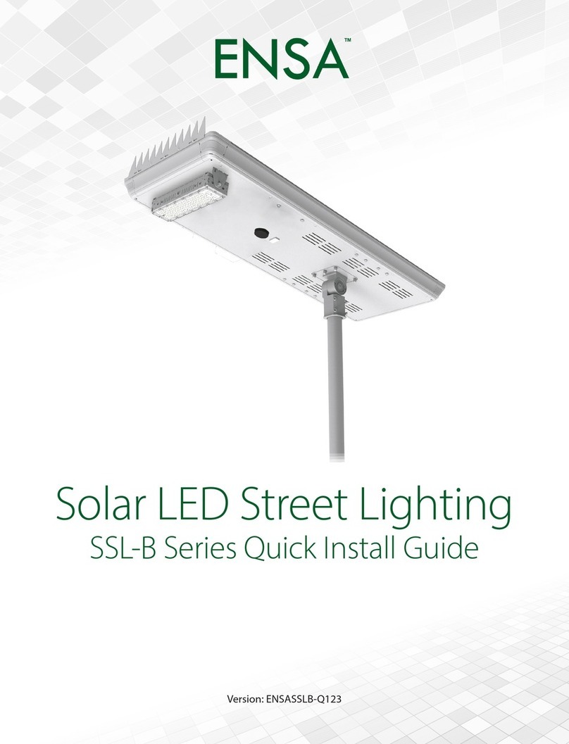
ENSA SSL-B Series User manual

Version: ENSASSLB-Q219A
SSL-B Solar Light Series
Installation Manual

ENSA SSL-B Solar Street Light Installation Manual - Version: ENSASSLB-Q219
2
1. Pre-Install Information
Thank you for purchasing a SSL-B Series Solar Street Light.
This install guide covers basic setup, installation and use of your light.
For more information, please visit:
www.ensalife.com
Motion Sensing Solar Panel with Street Light
Note: This solar panel system is fitted with undervoltage protection, which disconnects the load at
approximately 10.8V(SSL-B50) or 21.6V(SSL-B60). If you are not receiving any voltage on the output
wires, place the panel in direct sunlight for a minimum of one hour and re-test. The output will be
reconnected automatically when battery voltage reaches approximately 11.5V(SSL-B50) or
23.0V(SSL-B60).
Must be installed in direct sunlight. Shade will negatively impact performance.
This solar panel includes a motion-activated LED light. For more information, refer to 4. Solar Panel
LED Conguration.
•This product can withstand a class 12 storm. Storms above class 12 may damage the product.
•The Ingress Protection rating of this product is IP65, which is suitable for outdoor lighting, but
cannot be soaked in water.
• The solar panel is fragile, do not scratch or break the solar cell.
•Do not clean the solar panel with an abrasive sponge or soap. Use solar panel cleaning kits.
•The product contains a Lithium battery - comply with the air transport regulations when shipping,
•The longest storage period of solar street lamps is 6 months after they are fully charged. If they are
transported or stored for a long time, they need to be checked, recharged otherwise the battery
will be damaged.
•Charging temperature: 0~60°C. Discharge temperature: 20~60°C
• Do not store the product in a temperature exceeding 45°C.
1.1 Solar Light Information

Visit www.ensalife.com for support 3
1.2 Solar Light Specications
Model SSL-B50M SSL-B60M
Product Image
Series Name SSL-B Series Motion Activated Solar LED Street Lights
Light
Light Output 9400lm 11100lm
Luminous Efficacy >180lm/W
Colour Temperature 4000K natural white / 5700K cool white
Beam Angle 145° x 100° 145° x 100°
Rated LED Lifespan 50,000hrs
LED Testing LM80 / TM21 (available on request)
Power Consumption 50W 60W
Internal Battery 500Wh LiFePO41200Wh LiFePO4
Input Voltage 12.8VDC 25.6VDC
Operating Time 72~120 hours (intelligent mode, rainy weather) 120~168 hours (intelligent mode, rainy weather)
Light Bracket Adjustable bracket angle -30° ~ 30°
Solar Panel
Panel Type Monocrystalline silicon Monocrystalline silicon
Panel Wattage 120W 180W
Panel Conversion Rate ≥21% ≥21%
Panel Bracket Adjustable bracket angle -60° ~ 60°
Rec. Install Height 8 ~ 10m 8 ~ 10m
Detection
Motion Detection Microwave motion sensor
Detection Range Ø8 ~ 15m (height: 8 ~ 10m) Ø8 ~ 15m (height: 8 ~ 10m)
Light Mode
Settings
Normal Mode time period / Brightness
Morning Mode time period / Brightness
Sensor Mode time period / Brightness on motion / On-time delay / Brightness after motion
General
Ingress Protection IP65
Pole Diameter Ø50~60mm
Product Dimensions 1321 x 525 x 161mm 1496 x 685 x 161mm

ENSA SSL-B Solar Street Light Installation Manual - Version: ENSASSLB-Q219
4
Solar Panel Dimensions
50W
60W
1.3 Diagrams

Visit www.ensalife.com for support 5
50W
60W
Solar Panel Assembly Diagram
Lamp Body
Bird Spikes
Accessories
1.3 Diagrams (continued)
# Component Function
1Solar panel Convert solar energy
into electricity
2LED light Luminous component
3Microwave
sensor Detect object moment
4Lamp arm Fix the solar panel
5Bird spikes Keep birds away from
the solar panel
6Screws Fix bird spikes
7Safety rope Prevent the light from
falling
8T40 Torx
Tighten and release
the lamp arm anti-theft
screws

ENSA SSL-B Solar Street Light Installation Manual - Version: ENSASSLB-Q219
6
2. Installation
2.1 Installation Site
The solar panel should face north.
For the best solar panel efciency, ensure that sunlight is not blocked by buildings or trees.

Visit www.ensalife.com for support 7
1. Drill an 8mm hole in the pole
(minimum 15cm down from the top
of the pole) on the same side that
the camera will be mounted. This
is for the solar panel cable to run
through.
2. Feed the twin power cable
connected to your solar panel
through that hole
3. Place the solar panel bracket on top
of the pole, pointing north.
• Note: If you need to cover a different
area with the light beam, keep the
panel at after repositioning .
4. Securely fasten the included grub
screws to the bracket. Tighten the
locking bolts to prevent the grub
screws from loosening. (Fig. 2.1b)
• Note: For poles greater than 4m in
height, tapered poles are preferable
for camera stability and pole
strength.
8mm
Fig. 2.1a
Solar panel power cable drill location
Fig. 2.1b
Installed grub screws
Caution: Solar panel must be placed so it is in direct sunlight all day.
Any shading will greatly reduce the solar panel’s performance!
2. Installation
2.1 Mounting the Solar Panel to the Pole

ENSA SSL-B Solar Street Light Installation Manual - Version: ENSASSLB-Q219
8
To ensure your solar panel absorbs as much light as possible, it’s important to adjust the solar panel
angle to an ideal angle, depending on your region (refer to table below).
For Australia and all locations in the southern hemisphere, the solar panel must be tilted directly north.
Locations in the northern hemisphere must have the panel tilted directly south. The angle of tilt is
determined by the installation location and is calculated as installation latitude + 15°.
IMPORTANT: Failure to direct the panel correctly will cause system failure through insufcient power
Example tilt angles for Australian cities
Sydney Melbourne Canberra Perth Brisbane Hobart Adelaide Darwin
49° 53° 50° 47° 42.5° 58° 50° 27.5°
1. Use a at head screwdriver to remove the bracket cover.
2. Once the cover is removed, use a 10mm allen key to loosen the panel adjustment screw and tilt the
panel to the required angle with the LED light at the high side.
3. Tighten the bolt after adjusting the angle to secure the solar panel in place.
4. Replace the cover.
How to adjust tilt angle:
2.2 Adjusting the Solar Panel Tilt Angle
Tilt Angle
N°
For example, Sydney has a latitude of 34°, therefore the solar panel should be tilted directly north with
an angle of 34 + 15 = 49°.
If you are uncertain the of your area, Google makes it easy to nd the latitude for any location: For
example, searching for “latitude Newcastle NSW Australia” will return 32.9283° S, 151.7817° E. The
latitude is the rst number shown (32.9283) which rounds up to 33°.

Visit www.ensalife.com for support 9
Attach the safety rope between the solar light and the panel base, as pictured.
2.2 Adjusting the Solar Panel Tilt Angle (continued)
2.3 Safety Rope Installation
Fig. 2.2a
Angle adjustment
Light source angle adjustment
Lamp arm angle adjustment
Fig. 2.3a
Safety rope
installation
diagram

ENSA SSL-B Solar Street Light Installation Manual - Version: ENSASSLB-Q219
10
Note: Enabling the LED light and sensor will increase power consumption and reduce
battery power available for the system.
Incorrectly editing power settings can permanantly damage the solar panel, solar battery
and/or LED light. Consult ENSA for more information. Only edit power settings exactly
as outlined in this guide.
This section covers how to set up the motion-activated LED light on the solar panel. Our example
will show you how to congure your solar panel & light with the remote control, showing you the steps
required to set up the light to activate after motion is detected at night.
The solar panel’s motion-activated LED light is disabled by default. Solar panel conguration
requires the remote control (provided on request).
1. Battery Type: Type of battery installed in the solar panel (Li_Po=LiFePO4battery or Lead acid).
Warning: SSL-B50/60 uses LiFePO4battery, DO NOT change this parameter.
2. Boost Charge: Battery overcharge voltage. To protect the battery from overcharging, the battery
stops charging when it is above this voltage.
3. Voltage Low: Battery cut-off voltage. When the battery voltage falls below this value, output will
be disabled.
4. Recover Voltage: Minimum voltage for the battery to start. Battery output is enabled or resumed
from cut-off when battery voltage is above this value.
5. Power Saving: When turned on, the battery will adjust power output automatically to save energy
(On/Off).
6. Turn-On PV Voltage: The light turns on when the solar panel is below this voltage (dark). Note:
LED light turns on/off condition must meet other settings.
7. Output Current: Set the constant current output level.
8. Drive Mode:
Time Control - 5 individual intervals of maximum 9 hours each can be set to turn LED light on.
Move Sensor - Motion detect. The LED light will switch to higher intensity when it detects
movement. If no movement is detected, the intensity will be lower to save power. The intensity
can be adjusted for both settings to meet customer’s requirements.
9. Light Delay: The on-time delay after last detection motion. Suggested value: 30 seconds.
10. First/Second/Third/Fourth/Fifth Time: User-programmable light on/off schedule. Maximum 9
hours for each setting.
11. Light Ratio: Set light output (%) for when movement is detected.
12. Idle ratio: Set light output (%) for when no movement is detected.
Understanding Settings:
Before adjusting solar panel settings, familiarise yourself with the setting denitions below:
4. Solar Sensor Light Conguration (Optional)
4.1 Solar Sensor Light Introduction

Visit www.ensalife.com for support 11
Default pre-delivery time control settings:
Warning: Changing the above settings may damage the battery and charging circuit.
Period Light Ratio Idle Ration
First Time 9 Hours 10% 0%
Second Time 9 Hours 10% 0%
4.2 Default Settings
4.3 Remote Control
1. Take the solar panel outside and wait for it to charge in the sunlight for at least one hour.
2. Use the remote control and point it towards the black sensor at the back of the solar panel and
press Power. The remote control will be powered up. It will then try to connect the solar panel.
•If connection is successful, the LCD will show “Read OK”.
•If connection fails, the LCD will show “Disconnect”
Note: Direct sunlight can interfere with the transmission. The sensitivity of the transmitter is
higher when in dark environment.
Important: Do not change the device number otherwise it may not work properly.
The device number for this system is: PCC_G05
3. Press and hold the ON button to enable the solar light.
Fig. 4.3a
Solar panel remote control
Fig. 4.3b
Remote control LCD
Battery type: Li_PO for both SSL-B50 and SSL-B60
Battery and charging settings: (DO NOT ADJUST) SSL-B50 SSL-B60
Overcharge Protection Voltage (Boost Charge): 14.4V 28.8V
Cut-off Voltage (Voltage Low): 10.5V 21.0V
Start Up Voltage (Recover Voltage): 12.0V 24.0V

ENSA SSL-B Solar Street Light Installation Manual - Version: ENSASSLB-Q219
12
Power Press to power on. Press and hold for 2 seconds, then
release to power off the remote control.
Scroll Up Press to scroll up.
Scroll Down Press to scroll down.
Controller On Press and hold to enable the LED light control.
Controller Off Press and hold to disable the LED light control.
Enter Press to select item or conrm changes.
Back Press to select item or conrm changes.
Transmit Press to transmit parameters to the control board.
Test Press to test the LED light.
4.3 Remote Control (continued)
4. Point the remote control at the solar panel’s black sensor and scroll to the SysCong (System
Congure) and press (Enter) to enter the system conguration menu.
•Use and to scroll.
• Press Enter to begin editing values. The value will be shown in reverse colour.
•Use and to change the value.
• Press Enter again to conrm.
Note: The remote will power off automatically if no key is pressed for 3 minutes.
Five periods of time can be set to turn on the solar panel LED light. These periods can be set
with a min. of 0 and max. of 9 hours.
5. Point the remote control at the solar panel’s black sensor and press Transmit to update the
solar panel with your new conguration. If you hear a long beep, the conguration settings are
transmitted succesfully.

Visit www.ensalife.com for support 13
4.4 Disable Motion Activated LED Light
4.5 Check Solar Pabel On/Off Duration
4.6 Test LED Light
4.7 Lock/Unlock the Remote Control
To disable the LED light system again, simply change the Drive Mode from Move Sensor to Time Ctrl.
This will skip every Interval after the sun sets, so editing other values after this point is unnecessary.
To check the solar panel’s current settings conguration, scroll to the SysCong menu and press
Enter. This will show info such as photovoltaic voltage, battery voltage, output voltage, current and
power, temperature and total operating time in minutes and more.
1. Point the remote control at the solar panel’s black sensor and press Test.
2. Test the LED light by adjusting the light level on the remote screen with the Test button. This
scrolls through different light percentages. (100%, 70%, 50%, 30% and 0%)
After setup has been completed, you can lock the remote control to prevent changing the parameters
accidentally.
To lock/Unlock the remote control, press the Test, Enter and Back buttons together.
If you hear a single beep, the remote is locked. If you hear three beeps, the remote is unlocked.

ENSA SSL-B Solar Street Light Installation Manual - Version: ENSASSLB-Q219
14
Notes

Notes

Note:
All products, designs and software here are subject to change without prior written notice.
Version: ENSASSLB-Q219A
Other manuals for SSL-B Series
3
This manual suits for next models
2
Table of contents
Other ENSA Outdoor Light manuals
Popular Outdoor Light manuals by other brands

STEINEL
STEINEL professional XLED PRO 240 S manual

LIGMAN
LIGMAN MN-91261 Installation and service manual

Principal LED
Principal LED Street Wrap Gen 2 installation guide

HEPER
HEPER PUNTO S W Installation & maintenance instructions

Dayva
Dayva SL064LED user manual

Kingfisher
Kingfisher Viva-City Pro quick guide

Portfolio
Portfolio 00744 manual

Würth
Würth POWERQUAD M AC-R Translation of the original operating instructions

Briloner
Briloner MAL 3437 Mounting instructions

Buffalo
Buffalo CC036 instruction manual

WE-EF
WE-EF VFL500-SE Series Installation and maintenance instructions

TaoTronics
TaoTronics TT-DL23 user guide