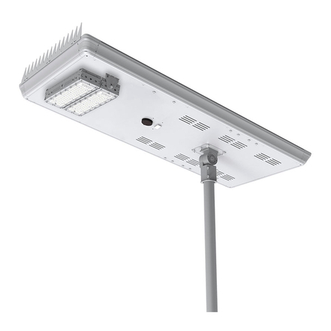
ENSA SSL-B Series User manual

Version: ENSASSLB-Q123
Solar LED Street Lighting
SSL-B Series Quick Install Guide

ENSA SSL-B Solar Street Light Installation Manual - Version: ENSASSLB-Q123
2
1. Pre-Installation
Thank you for purchasing a SSL-B Series Solar Street Light.
This install guide covers basic setup, installation and use of your light.
For more information & warranty details, please visit:
www.ensalife.com
1.1 System Overview
The ENSA™ SSL-B Series is comprised of motion-powered, solar-charged LED street lights, designed to deliver lighting
to any outdoor location. These pole-mounted lights provide superb coverage with a wide beam in a cool white colour.
The light can be set to always be active from dusk to dawn, or only when motion is detected with the adjustable motion
sensor.
These lights are fully self-sufcient, not requiring any external cabling. This makes them excellent for use in remote
locations such as rural roads, power stations & construction sites, as well as general use in streets, parks, schools,
farms and more.
# Component
1Solar panel
2LED light
3Microwave sensor &
RF Receiver
4Lamp arm
5Safety rope
6Bird spikes
7Screws

Visit www.ensalife.com for support 3
1.2.1 Solar Light Components
1.2.2 Operation Process
Solar Panel Assembly: This includes all solar panel
components including the panel itself, battery,
controllers, chassis & mounting arm.
The solar panel acts an ambient light sensor,
controlling dusk/dawn switch functions when it no
longer generates an adequate voltage from the sun.
This setting can be congured in Section 4.
The battery is Lithium Iron Phosphate (LiFePO4),
which has superior expected lifetime and temperature
tolerance compared to standard Lithium Polymer
batteries. It is also immune from thermal runaway
conditions to prevent res like standard LiPo batteries.
The mount arm of the solar panel offers 120° of tilt
on a Ø50~60mm pole, with an angle compass for
precise adjustment. It also has a spiked bird guard for
the panel & a safety wire rope.
Sensor Assembly: The dark circle on the underside
of the panel, the sensor assembly houses the infrared
receiver for the remote control for light conguration.
It also houses the microwave motion detector. This
detects motion in a circular area under the Solar Light
in a total diameter of Ø15m when mounted at 10m
above the ground.
Light Assembly: This comprises of a high efciency
LED array mounted on a 60° tilt-adjustable bracket to
control light distribution. The array’s mount position
can be moved to better orient the light.
SSL-B Series Solar Lights feature three main components that govern the function of the system. They are the solar panel
assembly (includes battery & solar controllers), the sensor assembly (including infrared remote receiver & microwave
motion detector), and the LED light assembly with adjustable bracket. These components are tightly integrated in the
operation of the entire system. See below for further explanation.
The SSL-B Series Solar Light is a highly customisable solar system, but how it operates is simple. The following details
the operation process of the SSL-B Solar Light after mounting.
1. During the day, the solar panel charges the battery. The LED light is off.
2. The solar panel detects that the sun has set. The LED light turns on.
3. The light is congured:
• To be at set brightness at different time periods during the night AND/OR
• Use the motion sensor to control brightness before & after movement is detected
4. The solar panel detects that the sun has risen. The LED light turns off.
5. The cycle repeats.
1.2 Function Overview
Fig. 1.2a
Underside of panel with detail on solar panel mounting arm,
sensor assembly and LED light assembly.

ENSA SSL-B Solar Street Light Installation Manual - Version: ENSASSLB-Q123
4
1.3 Model Specifications
Model SSL-B20M SSL-B30M SSL-B50M SSL-B60M
Product Image
Series Name SSL-B Series Motion Activated Solar LED Street Lights
Light
Light Output (max) 3900lm 5500lm 9400lm 11100lm
Luminous Ecacy >180lm/W
Colour Temperature 4000K natural white / 5700K cool white
Beam Angle 145° x 75° 145° x 100°
Rated LED Lifespan 50,000hrs
LED Testing LM80 / TM21 (available on request)
LED Power
Consumption (max) 20W 30W 50W 60W
Internal Battery 218Wh LiFePO4 320Wh LiFePO4 500Wh LiFePO4 1200Wh LiFePO4
Operating Voltage 12.8VDC 12.8VDC 12.8VDC 25.6VDC
Operating Time
(max) 72~120 hours (intelligent mode, rainy weather) 120~168 hours (intelligent
mode, rainy weather)
Light Bracket Adjustable bracket angle -30° ~ 30°
Solar Panel
Panel Type Monocrystalline silicon
Panel Wattage 56W 90W 120W 180W
Panel Conversion Rate ≥21%
Panel Bracket Adjustable bracket angle -60° ~ 60°
Rec. Install Height 5 ~ 7m 5 ~ 7m 8 ~ 10m 8 ~ 10m
Detection
Motion Detection Microwave motion sensor
Detection Range Ø8~15m (height: 5~10m)
Light
Mode
Settings
Normal Time period / Brightness
Morning Time period / Brightness
Sensor Time period / Brightness on motion / On-time delay / Brightness no motion
General
Ingress Protection IP65
Pole Diameter Ø50~60mm
Product Dimensions 821 x 450 x 161mm 1015 x 525 x 161mm 1321 x 525 x 161mm 1496 x 685 x 161mm

Visit www.ensalife.com for support 5
Solar Panel Dimensions
1.4 Solar Light Diagrams
SSL-B20MC
SSL-B30MC

ENSA SSL-B Solar Street Light Installation Manual - Version: ENSASSLB-Q123
6
SSL-B50MC
SSL-B60MC
1.4 Solar Light Diagrams (continued)

Visit www.ensalife.com for support 7
2. Solar Light Mounting & Installation
2.1 Choosing an Installation Site
This section covers choosing an installation site, selecting a pole for the Solar Light, mounting the Solar Light to the pole
and adjusting the Solar Light for optimal use.
Follow these guidelines to ensure you get the best use out of your Solar Light.
• To maximise exposure to the sun, solar panels must be installed to tilt north in the southern hemisphere and
south in the northern hemisphere.
• The Solar Light should not be installed in a location that blocks sun exposure by buildings or trees.
• See Section 2.4 for more detail.
• The Ingress Protection rating of this product is IP65, which is suitable for outdoor lighting, but cannot be soaked
in water.
• The solar panel is fragile, do not scratch or strike the solar cells.
• Do not clean the solar panel with an abrasive sponge or soap. Use solar panel cleaning kits.
• The longest storage period of solar street lamps is 6 months after they are fully charged. If they are transported or
stored for a long time, they need to be checked and recharged, otherwise the battery may be damaged.
• Charging temperature: 0~60°C. Discharge temperature: -20~60°C
• Do not store the product in a temperature exceeding 45°C.

ENSA SSL-B Solar Street Light Installation Manual - Version: ENSASSLB-Q123
8
When selecting a pole and foundation to install the solar panel on, there are several requirements to keep in mind:
• Using a tapered pole is recommended.
• The pole’s height should be equal to or higher than the solar panel’s recommended install height - this is 5 ~ 7m
for 20W/30W models & 8 ~ 10m for 50/60W models.
• The pole must have a spigot size of 60mm (adapters available).
• The pole must be strong enough to hold the weight of the solar panel - this can range up to 39kg (60W model).
• The foundation and fasteners should be strong enough resist high wind speeds. A shallow concrete foundation is
recommended.
ENSA™ can supply two pole models that t these install requirements. These galvanised poles include 4 x M20
foundation bolts (600 x 25mm), a bolt template ring and 60mm spigot adapter.
• SLR-POL4 (4.5m / 14.7ft)
• SLR-POL6 (6.0m / 19.7ft)
Consider frangible poles depending on requirements. Tilt poles may help with installation.
2.2 Choosing a Pole & Foundation

Visit www.ensalife.com for support 9
Caution: Solar panel must be installed so it is in direct sunlight all day.
Any shading will greatly reduce the solar panel’s performance.
2.3 Mounting the Solar Panel
Optional Bird Spikes
Safety Rope
Mounting the Panel
Adjust Light Angle

ENSA SSL-B Solar Street Light Installation Manual - Version: ENSASSLB-Q123
10
2.4 Adjusting the Solar Panel Tilt Angle
Tilt Angle
North
To ensure your solar panel absorbs as much light as possible, it’s important to adjust the solar panel angle.
For Australia and all locations in the southern hemisphere, the lower edge of the solar panel must point north. Locations
in the northern hemisphere must have the lower edge of the panel pointing south.
1. Use a 5mm Allen Key to remove the two panel adjustment bolts. (Fig. 2.5b).
Warning: The panel will freely move
after the bolts are removed.
2. Once the the bolts are removed, tilt the panel to the desired angle. Replace the bolts after adjusting the angle to
secure the solar panel in place.
3. Use a 8mm Allen Key to tighten the large bolts above the angle adjuctment bolts.
How to adjust tilt angle:
Fig. 2.4b
Solar panel angle bolt
We recommend adjusting the solar panel to a tilt angle that is optimised for winter.
This is to achieve better light absorbtion in winter and a consistent amount of light
absorbtion year-round.
The formula for calculating the optimal winter tilt is (Installation Latitude x 0.89)+24,
when the latitude is above 25°, or Installation Latitude x 0.87 if the latitude is less than
25°. Refer to Fig 2.5a for the optimal Winter Tilts for Australian Capital Cities.
For example Sydney has a latitude of 33.8688° S, therefore the panel should be tilted
directly north with an angle of 54° (33.8 x 0.89 = 30, then 30 + 24 = 54°)
If you are unable to use the optimal winter tilt or it is impractical to tilt the panel north,
while still illuminating the desired area, set a tilt angle of 5° and rotate the unit to the best
lighting position. Note that this will reduce charging performance, which may reduce
operating time.
City Angle
Adelaide 55°
Brisbane 48°
Darwin 10°
Perth 52°
Tasmania 61°
Sydney 54°
Victoria 56°
Fig. 2.4a
Optimal Winter Tilts for
Australian Captial Cities
Fig. 2.4c
Solar panel angle adjustment

Visit www.ensalife.com for support 11
3. Connect the Battery
The Solar Light is shipped with the battery disconnected from the system.
To activate the Solar Light, this battery must rst be reconnected. To reconnect:
1. Remove the “Battery Disconnected” sticker. (Fig 2.8a)
2. Find the two cables labeled “Battery”. (Fig 2.8b)
3. Taking note of the cable key, connect the two cables. (Fig 2.8c)
4. Twist the waterproof locking connector until tight. (Fig 2.8d)
5. Install the solar panel connection cover, included in the solar panel accessory bag. (Fig 2.8e)
Fig. 3.1a Fig. 3.1b Fig. 3.1c
Fig. 3.1d Fig. 3.1e
Once the battery is connected, a red LED will ash slowly inside the black sensor on the solar panel. If the battery is
connected correctly and this does not occur, this likely indicates low battery voltage - place the system in direct sunlight
for at least 1 hour to charge before continuing.

ENSA SSL-B Solar Street Light Installation Manual - Version: ENSASSLB-Q123
12
4. Advanced Solar Light Configuration
4.1 Remote Overview
Fig. 4.1a
Solar panel remote control
Remote Control Button Functions
Set Press to edit values, then press again to conrm
changes.
+Press to scroll down or decrease value.
-Press to scroll down or increase value.
Send Press to transmit parameters to the control board.
Test Press to test the light module. Toggle between 100%,
70%, 50%, 30% and 0% brightness.
Status Press to check the current status of the control board.
Parameters Press to read the current values set on the control
board.
ON Press to allow the control board & Light to function at
night time.
OFF
Press to set the control board & light to enter sleep
mode at night time.
Warning: If this is pressed, the remote
will not communicate with the control board at night time. Press
ON during daylight hours to fix this.
All conguration of the solar panel & LED street light is performed with the included RF remote. The remote interacts
with the panel’s RF receiver to control settings (the dark circle on the underside of the panel).
The remote control allows you to adjust solar panel, battery & sensor settings and then transmit them to apply the
conguration to the solar system. See initial menu options and button functions below:
This section covers how to fully congure the motion-activated 20W/30W/50W/60W LED light on the Solar Light. This
is recommended only for advanced users.
Warning: Modication to the LED light and sensor default values may increase power consumption, affect light
uptime and more.
Incorrectly editing settings can permanently damage the solar panel, battery and/or LED light. Performing
changes to contrary to those in this guide may cause damage to the panel not covered under warranty.
When using the remote to communicate with the panel, the remote will display an icon in the top right corner (Fig 5.1b)
to indicate the current send state (Sending, Send Succeeded, Send Failed). Three beeps indicate that the remote was
unable to communicate with the panel. A long single beep indicates that the communication was successful.
Fig. 4.1b
Remote Send States

Visit www.ensalife.com for support 13
4.2 Settings Detail
Each SSL-B Series Solar Light has default factory settings for light conguration and battery conguration. Below are
the functions of each setting in the SysConfig menu and the solar system default settings . Before adjusting solar panel
and light settings, familiarise yourself with the setting denitions below.
Warning: Changing settings without proper understanding of their function can permanently damage the solar
panel, battery and/or LED light. Use Section 4.2 as a reference only. Follow instructions in Section 4.3 before
modifying any settings on your SSL-B Series model. Contact ENSA for more information.
Name Remote Title Description Settings Default Settings
Battery Type BatType Type of battery installed in the solar panel Li 24 / Li12 / Li6 /
Li3 / Lead
Must use Li12 for SSL-B50 and Li24
for SSL-B60
DO NOT change this parameter
Sensing Delay S-D-Time
Countdown timer after last detected motion where light
output stays at Light Ratio setting before switching to
Idle Ratio setting.
See the next page for more details.
No / 1S ~ 60S /
2M ~ 60M All Models: 60S
PV Wake Up PV-Wake TBA Yes / No All Models: Yes
Light Control
Voltage L-Con-V
The solar panel acts as an ambient light sensor. Once
the solar panel voltage drops below the Light Control
Voltage, the rst Time Period/Light Ratio will begin
after Light Control Delay has elapsed.
1 ~ 11V All Models: 5V
Light Control
Delay L-Con-DT
The amount of time that must elapse after the solar
panel voltage drops below the Light Control Voltage
before the rst Time Period/Light Ratio will begin.
5S ~60S / 2M ~
60M All Models: 60S
Over Discharge
Voltage Over-DV Battery cut-off voltage. When the battery voltage falls
below this value, output will be disabled. 2.0V ~ 17.0V All Models: 11.5V
DO NOT change this parameter
Over Discharge
Recovery Over-DRV
Minimum voltage for the battery to start. Battery
output is enabled or resumed from cut-off when
battery voltage is above this value.
2.0V ~ 17.0V All Models: 12.5V
DO NOT change this parameter
Charge Voltage Chg-Volt
Battery overcharge voltage. To protect the battery
from overcharging, the battery stops charging when it
is above this voltage.
2.0V ~ 17.0V All Models: 14.4V
DO NOT change this parameter
Charge
Recovery Chg-CR-V When the battery level falls below this value, the
battery will resume charging. 9.00V ~ 25.00V All Models: 13.8V
DO NOT change this parameter
Low Temp
Change Cold Chg Low temperature cutoff 0°C ~ -40°V All Models: -35°
Low Temp
Work Heatwork High temperature cutoff 40°C ~ 90°V All Models: 65°
Load Current LED-Cur Set the constant current output level. 0.14A ~ 10.0A SSL:B50MC: 2.7A
SSL:B60MC: 1.75A
Power Saving SmartPow When turned on, the battery will adjust power output
automatically to save energy.
High / Mid / Small
/ No / USE All Models: USE
Derating Start
Value S-M-StaV
Voltage where the control board will begin to reduce
the power output from Load Current to Minimum
Current to save energy.
7.5V ~ 17.0V All Models: 12.6
Derating End
Value S-M-EndV Voltage where the contorl board will have reduced the
power output to Minimum Current to save energy. 7.5V ~ 17.0V All Models: 11.6
Minimum
Current
Min-Cur
The minimum constant current output level All Models: 0.1A
Load
Parameters
LoadPowSet
Enter the Load Parameters section.
See the next page for more details. --
Factory Reset Re-det Reset remote back to factory parameters. Yes / No All Models: No

ENSA SSL-B Solar Street Light Installation Manual - Version: ENSASSLB-Q123
14
4.3 Settings Detail (continued)
Name Remote Title Description Settings Default Settings
(Sense)
Time Period STime1-9
User-programmable light on/off schedule. Maximum
15 hours for each setting. Time intervals begin once
the sun has set.
00.00 ~ 15.00
All Models:
S-Time1: 6.00
S-Time2: 4.00
S-Time3: 8.00
S-Time4-9: 0.00
(Sense)
Light Ratio S-C-Pow1-9 Set light output (%) for when movement is detected. 0% ~ 100%
All Models:
S-C-Pow1: 100%
S-C-Pow2: 60%
S-C-Pow3: 100%
S-C-Pow4-9: 0%
(Sense)
Idle Ratio S-L-Pow1-9 Set light output (%) after last detected movement and
after Sensing Delay has elapsed. 0% ~ 100%
All Models:
S-C-Pow1: 30%
S-C-Pow2: 20%
S-C-Pow3: 30%
S-C-Pow4-9: 0%
(Sense)
Morning Light
Time
MorTime The time period the light will be on for during daylight
hours. 00.00 ~ 15.00 All Models: 0.00
(Sense)
Morning Light
Ratio
S-C-Pow Set light output (%) for when movement is detected
during the Morning Light Time period 0% ~ 100% All Models: 0%
The Load Parameters section will change depending on on how Sensing Delay is congured. The rst Time Period
begins once sunset has been detected via Light Control Voltage. The second Time Period begins once the rst Time
Period has elapsed.
If Sensing delay is set to No the light will be Time Control mode. In Time Control Mode the light you can set the Time
Period (1st-9thTime) and Light Ratio (1st-9thPower) to determine the light brightness for designated time periods.
If Sensing Delay is set to a second or minute value (e.g 20S), the light will be in Sense Mode. In Sense Mode you
can set the Time Period (STime1-9), Light Ratio (S-C-Pow1-9) and Idle Ratio (S-L-Pow1-9) to determine the light
brightness when movement is detected (Light Ratio) and the light brightness when motion has stopped being detected
and Sensing Delay has elapsed (Idle Ratio).
Name Remote Title Description Settings Default Settings
(Time)
Time Period 1st-9thTime
User-programmable light on/off schedule. Maximum
15 hours for each setting. Time intervals begin once
the sun has set.
00.00 ~ 15.00
All Models:
1stTime: 6.00
2ndTime: 4.00
3rdTime: 8.00
4th-9thTime: 0.00
(Time)
Light Ratio 1st-9thPower Set light output (%). 0% ~ 100%
All Models:
1stPower: 100%
2ndPower: 60%
3rdPower: 100%
4th-9thPower: 0%
(Time)
Morning Light
Time
MorTime The time period the light will be on for during daylight
hours. 00.00 ~ 15.00 All Models: 0.00
(Time)
Morning Light
Ratio
MorPower Set light output (%) during the Morning Light Time
period 0% ~ 100% All Models: 0%
Time Control Mode
Sense Control Mode
Load Parameters

Visit www.ensalife.com for support 15
4.4 Change LED Light Settings
2. Point the remote control at the solar panel’s black sensor and press Send Key to update the solar panel with
your new conguration. If you hear a long beep, the conguration settings are transmitted successfully.
Fig. 5.4b
Sense activated light settings
1. Point the remote control at the solar panel’s black sensor and scroll to the Load Pow Set (Load Parameters) and
press Set to enter the system conguration menu.
• Use and to scroll.
• Press Set to begin editing values. The value will be shown in reverse colour.
• Use and to change the value.
• Press Set again to conrm.
Note: The remote will power off automatically if no key is pressed for 3 minutes.
Nine periods of time can be set to turn on the solar panel LED light. These periods can be set with a min. of 0 and max.
of 15 hours. (9 hours by default - refer to 5.2 Settings Detail)
To disable the LED light, simply change the Sensing Delay to No. Then set each time period to 0 hours, and each light
ratio to 10%.
Fig. 5.4a
Time activated light settings
After setup has been completed, you can lock the remote control to prevent settings from being accidentally changed,
or changed by somebody else.
To Lock/Unlock the remote control, press the Off and + buttons together for three seconds.
When the remote gives two short beeps, the remote is now locked. Repeat these steps to unlock the remote.
If the remote has been reset via the Factory Reset option, the Remote Control Type will need to be recongured before
it can communicate with the panel.
Press the and buttons together for three seconds to open the Remote Control Settings (RemotSet) page.
Set CommType to RF and RF-Dst to 10. Cur-Pasw should be 0000. If it has been changed, use the Chg-Pasw option
4.5 Disable LED Light
4.6 Lock/Unlock the Remote Control
4.7 Remote Control Type Selection

ENSA SSL-B Solar Street Light Installation Manual - Version: ENSASSLB-Q123
16
4.8 Check Solar Panel Status
To check the solar panel’s current state press status, (or press and hold status for three seconds and select
RunState)This will show info such as photovoltaic voltage, battery voltage, output voltage, current and power,
temperature and total operating time in minutes and more.
Name Remote Title Description
System State SysState
On connecting to the panel, the Solar Panel Status can be in 3 states.
DCHG: When the Solar Light is on
FULL: When the Solar Panel is fully charged
CHG: When the Solar Panel is charging
OV-D: When the system is below Over Discharge Voltage
L-OPN: when the remote hasn’t connected or the system is above Charge Voltage
Battery Voltage BatVolt Battery voltage as measured by the charge controller output.
Photovoltaic Voltage PV-Volt Solar panel voltage as measured by the charge controller input.
Charge Current Chg-C Current being supplied to the battery.
Charge Power Chg-P Power being supplied to the battery.
Charge Time Chg-AH Ah charged during this session.
Load Voltage LoadVol Voltage being supplied to the LED light.
Load Current LoadCurr Current being supplied to the LED light.
Load Power Load-P Power being supplied to the LED light.
Lighting-up Time Light-T Total running uptime of the Solar Light, measured in hours & minutes.
Sensing Time Sensor-T Total running time the sensor has detected movement, measured in hours & minutes.
Discharge Ah DisC-AH Ah discharged during this session.
Ambient Temperature Temp Temperature inside the Solar Light.
Running days RunDays Total running uptime of the Solar Panel, measured in hours & minutes.
Current Run State

Note:
All products, designs and software here are subject to change without prior written notice.
Version: ENSASSLB-Q123
Other manuals for SSL-B Series
3
This manual suits for next models
4
Table of contents
Other ENSA Outdoor Light manuals
Popular Outdoor Light manuals by other brands

Claypaky
Claypaky C52321 operating instructions

Growth Product
Growth Product 18231-001 Assembly instructions

FLOS
FLOS TOIO manual

WAC Lighting
WAC Lighting dweLED WS-W37612 Installation instruction

Hyundai Lighting
Hyundai Lighting Garden Glow installation manual

TVILIGHT
TVILIGHT CitySense Plus installation manual