Entec Solar E-1500 User manual
Entec Solar
User manual
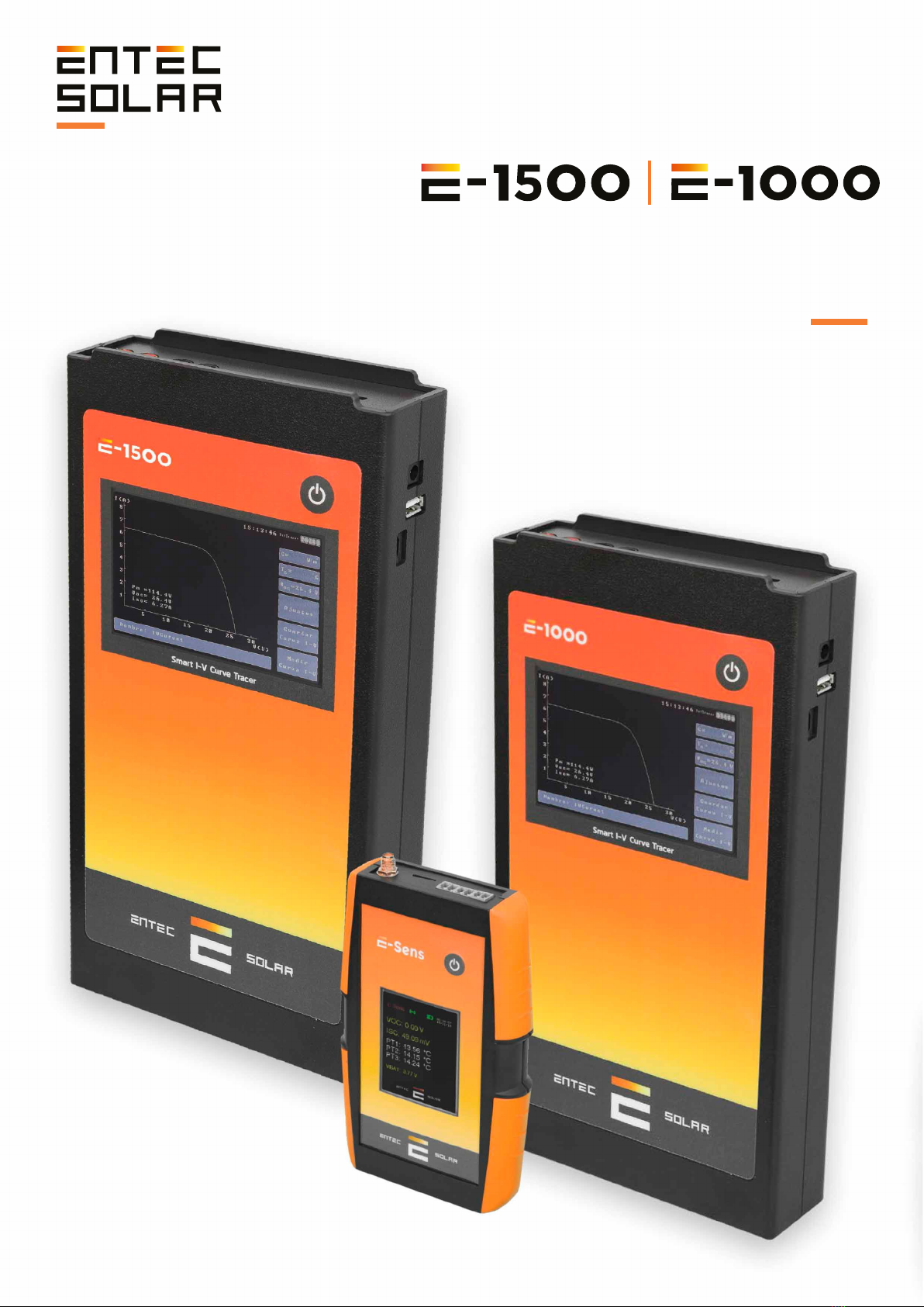
E-1500 / E-1000
E-Sens y E-Temp
Smart I-Vcurve tracer
V1.2

2 www.entecsolar.es
Índice
0. Thank You Letter.............................................04
1. Warnings..........................................................05
1.1. Used Symbols......................................................06
1.2. Safety Measures during Use............................07
2. Overview..........................................................08
2.1. Equipment Functionality...................................09
2.2. External Connectors and Part
Descriptions...................................................................10
2.2.1. E-1500................................................................10
2.2.2. E-1000................................................................11
2.2.3. E-Sens.................................................................12
2.2.4. E-Temp................................................................13
2.3. Description of Elements on the Initial
Screen...................…........................................................14
2.3.1. E-Sens.................................................................14
2.3.2. E-Temp................................................................15
2.4. Supply Scope........................................................16
3. Measured Quantities and Operating
Conditions ............................................................17
3.1. Measured Quantities..........................................17
3.2. Operating Conditions.........................................18
4. Preparations Prior to Measurements..........19
4.1. First Use of the Device.......................................19
4.2. Battery Charging.................................................19
4.3. Inserting the Memory Card...............................20
4.4. Initial Configuration............................................20
4.5. Mounting Irradiance and Temperature
Sensors and Connecting to E-Sens........................21
4.5.1.Irradiance Sensor..............................................21
4.5.2.Temperature Sensor.........................................21
4.6. Connection of the Module or Generator
Under Test .....................................................................22
5. Configuration and Operation........................24
5.1. Startup....................................................................24
5.2. Main Screen...........................................................25
5.2.1. Main Screen Information................................25
5.2.2. Main Screen Controls.....................................26
5.2.2.A. TC Sensor Selection...................................26
5.2.2.B. Access to Settings Menu...........................26
5.2.2.C. Save Curve.....................................................26
5.2.2.D. Measure Curve.............................................26
5.2.2.E. File Name.......................................................26
5.3. I-V Curve Measurement....................................26
5.3.1. General Considerations.................................26
5.3.2. Manual Measurement....................................28
5.3.3. Auto-Measurement........................................28
5.3.4. Continuous Measurement............................30
5.3.5. Barcode Registration......................................31
5.3.6. Temperature Measurement with
E-Temp ..........................................................................31
5.3.7. Measurement Process Results....................32
5.4. Saving I-V Curve.................................................32
5.4.1. Manual Save......................................................33
5.4.2. Automatic Save................................................32
5.4.3. Saved File Format............................................33
5.5. Settings................................................................. 34
5.5.1. Bifacial Measurement....................................35
5.5.2. Load Module.....................................................35
5.5.3. Measurement Settings...................................36
5.5.3.A. G Limit............................................................36
5.5.3.B. V Range..........................................................37
5.5.3.C. Measurement Tolerance............................37
5.5.3.D. Tc Comp..........................................................38
5.5.4. Module Settings...............................................38
5.5.4.B. Save and Load Module
Configurations..............................................................38
5.5.5. Generator Settings..........................................40
5.5.6. Sensor Settings................................................41
5.5.6.A. Irradiance Sensor.........................................41
5.5.6.B. Temperature Sensor...................................41
5.5.7. Continuous Measurement............................42
5.5.8. Auto Save...........................................................42
5.5.9. Auto Measurement.........................................42
5.5.10. Barcode (Optional).......................................42
5.5.11. Others...............................................................43
5.5.11.A. Set Time/Day..............................................43
5.5.11.B. Update Firmware......................................43
5.5.11.C. Generate Report........................................43
“Innovative technological developments for the photovoltaic solar energy industry”
3 www.entecsolar.es
Índice
5.5.11.D. Language Selection..................................45
5.5.11.E. Sound On/Off..............................................45
5.5.11.F. Info..................................................................45
5.5.12. APK Connect...................................................45
5.5.13. Display STC Curve........................................46
6. Bifacial Curve Configuration and
Measurement.......................................................47
6.1. Required Materials..............................................47
6.2. Assembly and Connection................................47
6.3. Bifacial Operation Procedure...........................49
7. Data Download.............................................. 51
7.1. Data Download to PC........................................ 51
7.2. Opening Saved Files in a Data
Sheet............................................................................... 51
8. User Manual - APK Connect..........................54
9. User Manual - I-V Curve App........................58
9.1. Introduction...........................................................58
9.2. Plant Creation.......................................................58
9.3. Uploading Files and Data Processing...........60
9.3.1. File Upload.........................................................60
9.3.1.1. Automatic File Upload via Rosetta..........60
9.3.2. Data Processing................................................61
9.4. Results Visualization..........................................62
9.4.1. Statistical Analysis..........................................62
9.4.2. Numeric Summary...........................................62
9.4.3. Curve Visualization..........................................62
9.4.4. Reports................................................................62
10. Quick Measurement Guide..........................63
11. Technical Specifications ..............................64
12. Warranty, Calibration, and Repair............68
13. Common Errors and Solutions...................69
“Innovative technological developments for the photovoltaic solar energy industry”
4 www.entecsolar.es
Thank you for purchasing
the Entec Solar I-V Curve Tracer.
With the goal of creating hardware tools to facilitate
the work of individuals, Entec Solar has developed
the E-1000 and E-1500 I-V Curve Tracers. Both have
been developed in collaboration with the company
QPV ( ).This company specializes in
audits and quality control of large photovoltaic power
plants and has highlighted the current needs in the
field of I-V curve measurement. The combination of
Entec Solar's hardware development expertise and
QPV's experience in I-V curve measurement has
resulted in the fastest and most innovative I-V curve
tracers on the market, all with unparalleled
measurement precision.
This high-precision instrument allows for the
measurement of several hundred I-V curves per
working hour, whether from photovoltaic modules or
strings up to 1500V and 35A. In addition, it
incorporates several new features, including a
barcode reader for automatic identification of the
module under test and its position in the installation;
an automated report generation tool to reduce
processing time; an automatic measurement option to
free up the operator's hands during panel connection
and disconnection; a wireless sensor (E-Sens) with a
communication range of several hundred meters to
measure irradiance and temperature conditions; a
mobile phone application for remote device control;
and many more options that will revolutionize your
I-V curve measurement campaigns.
Furthermore, through a WiFi connection, the I-V curve
tracer synchronizes with PVET® servers
(www.pvet.es), facilitating storage, comparison, and
post-processing of measurement campaigns for fault
diagnosis in your plants.
www.qpv.es
(www.pvet.es)
“Innovative technological developments for the photovoltaic solar energy industry”

5 www.entecsolar.es
1. Warnings
The E-1000 is an I-V curve tracer designed to
work with voltages of up to 1,000 VDC, which can
be hazardous to humans. That is why the E-1000
and its accessories should only be used with the
components supplied by Entec Solar. Before using
the E-1000, read this manual in its entirety and
pay special attention to the points related to
electrical safety and the points highlighted by the
warning and risk of electric shock symbols (see
section 1.2).
The use of unapproved accessories can affect the
safety of this device and can cause considerable
damage to equipment or people. The E-1000
should be used only by personnel trained in low
voltage electrical installations and preferably with
specific training in photovoltaic solar energy
installations. Entec Solar will not assume any
responsibility for damages caused due to misuse
of the device or its associated components. The
E-1000 and its components must not be
manipulated, modified, opened, or repaired by any
personnel other than those of Entec Solar. Any
tempering of the device by third-party personnel
may result in loss of equipment warranty. In case
the E-1000 or any of its associated accessories or
components need repair or re-calibration, please
contact Entec Solar or any of its distributors.
“Innovative technological developments for the photovoltaic solar energy industry”

6 www.entecsolar.es
1.1. Used Symbols
• Double or reinforced continuous insulation (protection class II).
•
•
•
•
i
Caution danger! Pay attention to the documentation! This
symbol is placed in front of instructions that must be followed
to prevent material damage and harm to individuals.
Take into account all the documentation provided with the
measuring instrument.
Caution high voltage, danger of death.
Measurement instruments should not be disposed of with
household waste.
“Innovative technological developments for the photovoltaic solar energy industry”

7 www.entecsolar.es
1.2. Safety Measures During Use
The I-V Curve Tracer has been designed and
manufactured in accordance with the standard
EN61010-1:2011 "Safety Requirements for
Electrical Equipment for Measurement, Control,
and Laboratory Use" and has been certified by an
independent laboratory under the criteria of this
standard as equipment with reinforced insulation
CAT II 1000V DC.
To ensure that all safety measures designed into
the equipment are met, the following rules must
be strictly adhered to:
- Before using the equipment, carefully read the
entire manual and pay special attention to points
related to electrical safety.
- Use the equipment only for measurements in
photovoltaic installations. Other current or
voltage sources that are not of photovoltaic origin
can damage the measuring instrument.
- Disconnect the photovoltaic circuit under test
from any other connected circuit (e.g., inverter,
charge controller, battery, etc.) before connecting
the I-V Curve Tracer.
- Before taking measurements, ensure that they
do not exceed the operating limits of the
equipment: for the E-1000, these are 1,000V and
20A; for the E-1500, they are 1500V and 35A. A
measurement that exceeds these limits could
cause irreparable damage to the equipment.
- The equipment should only be used by
personnel trained in low voltage electrical
installations who have been specifically trained in
the use of this equipment.
- During measurements, use recommended
personal protective equipment (PPE) for electrical
measurements: insulated gloves, safety boots,
face shield, etc.
- Never disconnect measurement cables while a
measurement is being performed. This could
cause an electric arc and damage to the
equipment and individuals.
- Avoid contact with the photovoltaic circuit under
test and with any other metallic part in the vicinity.
- Avoid exposing the equipment to direct sunlight.
- Do not perform measurements in humid
environments or in rainy conditions, and ensure
that no liquids enter the equipment.
- Do not perform measurements in environments
with gas, explosive materials, flammable
substances, or dusty environments.
- Use only genuine Entec Solar original
accessories.
- For the E-1500, a 1500V fuse holder is provided
that connects to the four-point cables via an MC4
connector. Entec Solar always recommends its
use during measurements as an additional
protective measure.
“Innovative technological developments for the photovoltaic solar energy industry”

8 www.entecsolar.es
2. General Description
The Entec Solar I-V Curve Tracer consists of a
main unit, either the E-1500 or E-1000, which is
complemented by several devices (E-Sens,
E-Temp, barcode reader), each with its specific
functionality.
The I-V Curve Tracer, either the E-1500 or
E-1000, is the device responsible for the physical
measurement of photovoltaic panels. It connects
using four-point cables and is in charge of
measuring voltage and current, receiving
information from other devices, processing the
data, displaying it on the screen, and storing it.
The E-Sens is an independent device that
complements the I-V Curve Tracer. Its purpose is
to measure irradiance and temperature values of
the provided calibrated cell, as well as the
temperature of up to three optional PT-1000
sensors. It needs to be physically connected to the
calibrated cell for measurements. Communication
with the I-V Curve Tracer is automatically done
through radio waves, eliminating the need for a
physical connection. This feature allows for more
flexible positioning.
The E-Temp is an optional device designed for
measuring the temperature of photovoltaic
panels. While there are various ways to measure
panel temperature, Entec Solar has developed
this quick and convenient solution. It operates
independently and communicates through radio
waves, offering flexibility and making
temperature measurements in less accessible
locations easier.
The barcode reader is an optional device designed
to read identification labels found on photovoltaic
modules. The reader must be physically
connected to the I-V Curve Tracer via USB and
activated by the operator. It is particularly useful
for measuring I-V curves of modules, as it enables
unique identification of each measurement using
the module's barcode.
“Innovative technological developments for the photovoltaic solar energy industry”

9 www.entecsolar.es
2.1. Equipment Functionality
El E-1500 / E-1000 puede ser utilizado de manera
autónoma o de manera conjunta con otros
accesorios, como el E-Sens, el E-Temp o el lector
de código de barras.
El uso del E-1500 / E-1000 junto con todos sus
accesorios proporciona la mayor comodidad y
precisión en la medida de curvas I-V.
A continuación, se listan todas las funcionalidades
que proporcionan el E-1500 / E-1000 y todos sus
accesorios.
-Medida de la tensión de circuito abierto, VOC.
(E-1500 / E-1000)
-Medida de la corriente de cortocircuito, ISC.
(E-1500 / E-1000)
-Medida de la curva I-V a 4 puntas hasta 1500V y
35A. (E-1500 / E-1000)
-Medida de la irradiancia a través de una célula
calibrada o módulo de referencia (E-SENS)
-Medida de hasta tres puntos de temperatura
mediante PT-1000 (E-SENS)
-Medida de temperatura de un módulo de
referencia (E-SENS)
-Medida de temperatura mediante sensor de
infrarrojo (E-Temp)
-Transmisión inalámbrica de los datos
de irradiancia y temperatura (E-1500 / E-1000,
E-Temp)
-Extrapolación de las curvas I-V medidas a STC
mediante IEC-60891 (E-1500 / E-1000)
-Selección del sensor de temperatura para la
extrapolación (E-1500 / E-1000)
-Lectura del código de barras del módulo bajo
ensayo (E-1500 / E-1000)
-Generación automática de informes
diarios (E-1500 / E-1000)
-Modo automático de medida (E-1500 / E-1000)
-Modo automático de guardado de la medida
(E-1500 / E-1000)
-Modo de medida continua mediante periodo
seleccionable (E-1500 / E-1000)
-Almacenamiento de datos en tarjeta SD extraíble
(E-1500 / E-1000)
-Almacenamiento de datos en tarjeta MicroSD
extraíble (E-Sens)
-Lectura de datos mediante conexión inalámbrica
WiFi (E-1500 / E-1000)
-Visualización y control de medidas a través de
App móvil (E-1500 / E-1000)
“Innovative technological developments for the photovoltaic solar energy industry”

10 www.entecsolar.es
2.2. External Connectors and Parts Description
2.2.1. E-1500
Figure 2.3 displays the side connectors
and their description.
2. Battery Charger
Jack Connector
1.
USB Connector for
Barcode Reader
Connection
Figure 2.1 shows the upper connectors
and their description.
1. SD Card Slot
2. Negative Terminal Inputs for I-V
Curve Measurement
3. Positive Terminal Inputs
for I-V Curve Measurement
Figure 2.2 displays the front connectors
and their description.
1. Power Button
2. Touchscreen Display
ATTENTION: Avoid prolonged exposure to direct sunlight.
“Innovative technological developments for the photovoltaic solar energy industry”
11 www.entecsolar.es
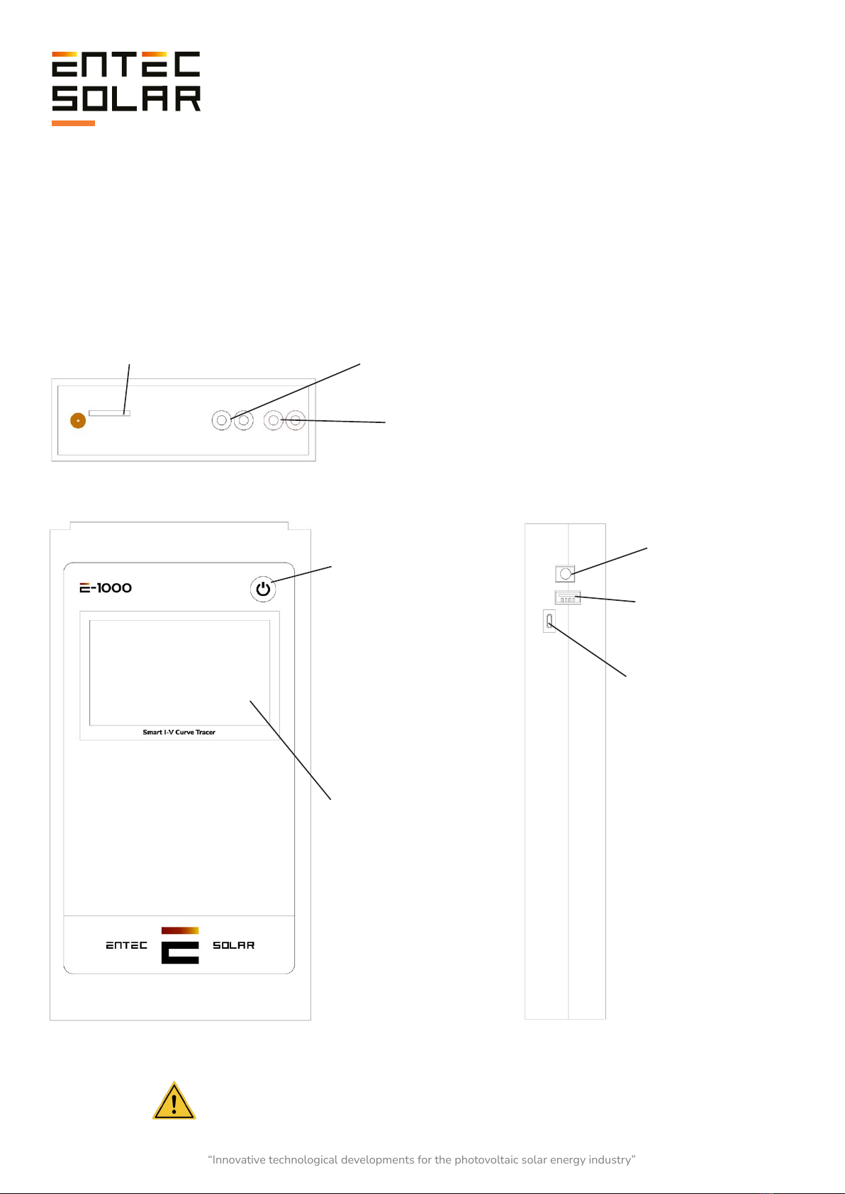
2.2.2. E-1000
Figure 2.6. Shows the side connectors
and their description.
1. Battery charger
Jack connector
2. USB connector for
barcode reader
connection
3. micro USB connector
for SD card access
Figure 2.4. Shows the top connectors and their description.
1. SMA connector for external antenna
2. SD card slot 3. Negative pole inputs for I-V curve measurement
4. Positive pole inputs for I-V curve measurement
Figure 2.5. Shows the front connectors
and their description.
1. Power button
2. 5-inch color
touchscreen.
Resolution 800x480
ATTENTION: Avoid prolonged exposure to direct sunlight.
“Innovative technological developments for the photovoltaic solar energy industry”

12 www.entecsolar.es
2.2.3. E-Sens
Figure 2.10. Illustrates the side connectors
and their description.
1.USB connector
for battery
charging
2. Battery charging
LED indicator
Figure 2.9. Illustrates the front connectors
and their description.
1. Power button
2. Color display
1. SMA connector for external antenna
2. microSD card slot
Pt1000-3
1. Reference cell PT1000
2. .Reference
cell
Pt1000-2
Pt1000-1
ATTENTION: Avoid prolonged exposure to direct sunlight.
Figure 2.7. Shows top connectors
and its description.
Figure 2.8. Shows the connectors
below and their description.
“Innovative technological developments for the photovoltaic solar energy industry”
13 www.entecsolar.es
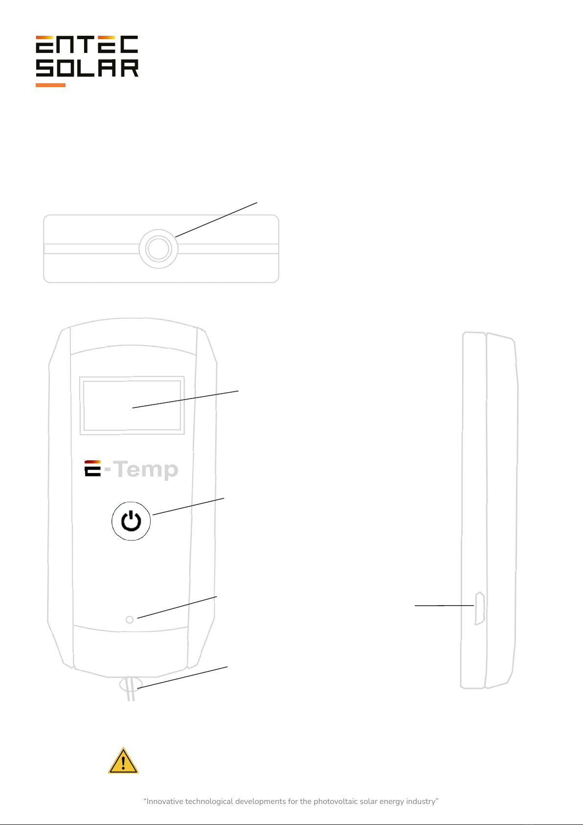
2.2.4. Optional: E-Temp (IR Sens)
Figure 2.13. Illustrates the micro USB
charging port on the side.
1. Micro USB
port.
Figure 2.12. Illustrates the front display and button.
2. Power button.
1. Color display.
Figure 2.11. Illustrates the infrared sensor on the top.
1. Sensor
3. LED.
4. Grip tape.
ATTENTION: Avoid prolonged exposure to direct sunlight.
“Innovative technological developments for the photovoltaic solar energy industry”

14 www.entecsolar.es
2.3. . Description of Elements on the
Initial Screen
2.3.1. E-Sens
In this section, we will focus on the E-Sens and
E-Temp devices, as the elements on the curve
tracer screen are available in Section 5 of this
manual.
To power on and off the E-Sens, press the black
button on the top right of the screen. While the
device is booting up, the loading screen will be
displayed for a few seconds.
On this screen, the message "Initializing..." is
shown, along with two important pieces of
information. The first is "SN," which corresponds
to the Serial Number of the device. The second is
"Fw V," which corresponds to the Firmware
version of the device.
Once the device has finished initializing, the main
E-Sens screen will be displayed. This is the screen
where all the device information is shown.
In the upper bar, from left to right, you will find the
following elements:
- Device logo
- MicroSD detected and initialized icon
- Battery status icon
- Date and time
The following data is displayed in a vertical order:
- ISC: Measurement of the voltage of the
calibrated reference cell in millivolts to obtain
irradiance.
- Tc Isc: Temperature measurement of the PT1000
of the calibrated reference cell.
- PT1: Temperature measurement of channel 1.
- PT2: Temperature measurement of channel 2.
- PT3: Temperature measurement of channel 3.
- VBAT: Measurement of the battery voltage.
Figure 2.14. E-Sens screen during device
startup.
Figure 2.15. E-Sens screen during device
startup.
“Innovative technological developments for the photovoltaic solar energy industry”
15 www.entecsolar.es
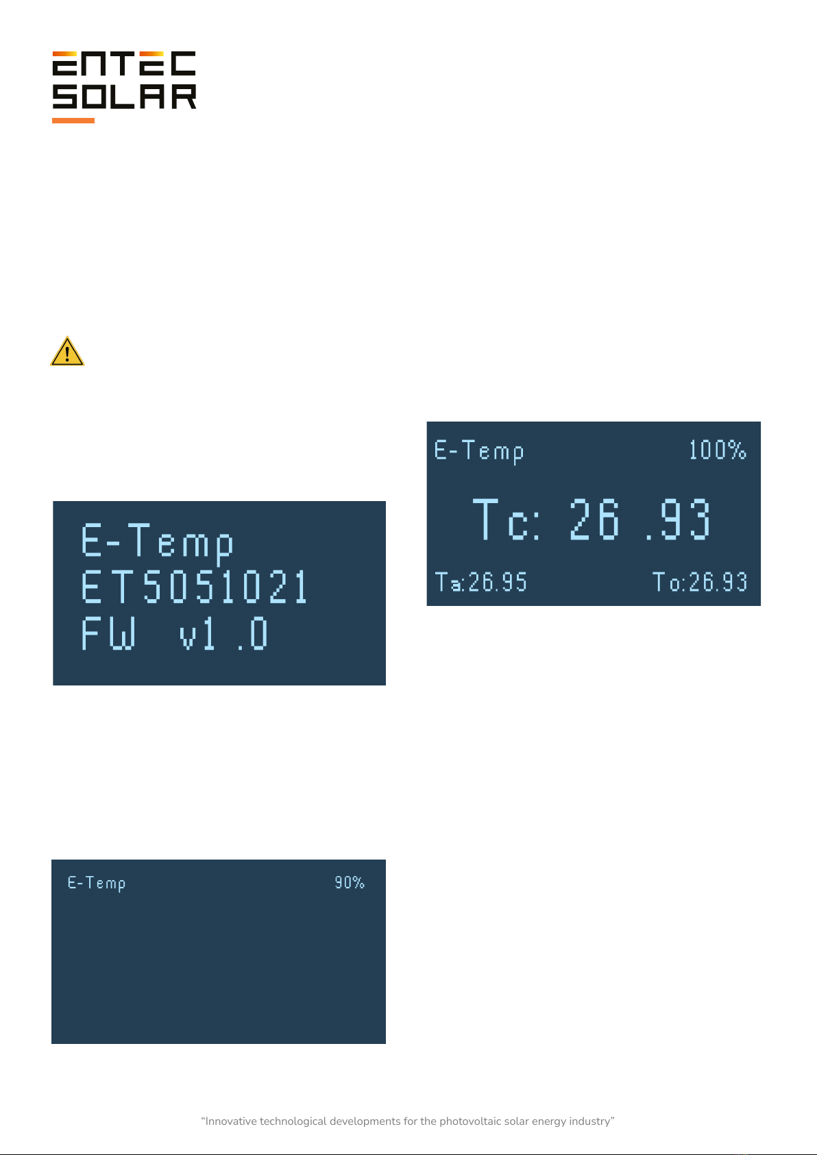
2.3.2. E-Temp
To power on the E-Temp, briefly and gently press
the power button once, and wait for a couple of
seconds until the startup screen is displayed.
Similarly, to turn off the device, press and hold
the same button for 5 seconds.
IMPORTANT: During startup, it is important
not to press the button multiple times in
succession or press it for an extended period, as
this may turn off the device.
The initial data displayed includes the device
name, the device's serial number, and the
firmware version.
Once the device initialization is complete, the
standby screen will be shown. In this mode, the
device is ready to take measurements but
displays minimal information to save battery
power by reducing screen energy consumption.
Figure 2.16. E-Temp screen during device startup.
Figure 2.18. E-Temp measurement screen.
Figure 2.17. E-Temp standby screen.
Once the device initialization is complete, the
standby screen will be shown. In this mode, the
device is ready to take measurements but
displays minimal information to save battery
power by reducing screen energy consumption.
Subsequently, three temperatures will be
displayed on the screen:
- Tc: This corresponds to the temperature of the
measured point and is located in the center,
displayed larger. This is the temperature stored in
the curve tracer's SD card data.
- Ta: This corresponds to the ambient
temperature, located at the bottom left.
- To: This corresponds to the temperature of the
temperature sensor packaging. Excessive
temperature can affect the accuracy of the device.
It is located at the bottom right.
When performing the measurement, the data will
be displayed on the screen for approximately five
seconds. At the end of this period, the device
returns to the standby state.
Please note that the same button is used to power
on the device, take measurements, and power off
the device, so you should be cautious when
pressing it. It is important not to press the button
multiple times in succession or press it for an
extended period.
“Innovative technological developments for the photovoltaic solar energy industry”

16 www.entecsolar.es
Figure 2.19. Devices and accessories included.
2.4. Supply Package
The E-1000 can be purchased in its basic version
or with various options. Below is a list of
accessories included in the basic version and
optional accessories.
Included in the Basic Version:
- 1 x E-1500 / E-1000.
- 1 x E-Sens.
- 1 x Padded transport case with wheels.
- 1 x Set of four-point measurement cables with
MC4 terminals.
- 1 x SD card for E-1000.
- 1 x MicroSD card for E-Sens.
- 1 x Charger for E-1000.
- 1 x Set of crocodile clips.
- 1 x USB cable for charging E-Sens.
- 1 x Calibrated reference cell.
- 1 x PT-1000.
- 1 x Wireless communication antenna.
- 1 x 1500V fuse in cable (for E-1500).
Optional Accessories:
- Barcode reader.
- Infrared temperature sensor (E-Temp).
- Access to PVET for data storage and advanced
analysis.
- Additional PT-1000 sensors.
“Innovative technological developments for the photovoltaic solar energy industry”
17 www.entecsolar.es
3. Measurement Quantities and Operating Conditions
3.1. Measured Quantities
Unlike measuring I-V curves under controlled
conditions, such as with a flash tester, measuring
I-V curves in the field under variable operating
conditions requires extrapolation of the measured
curves to standard test conditions (STC).
The E-1500 performs this extrapolation
automatically according to the procedure
described in IEC 61829 and based on
measurements of irradiance, module
temperature, and the I-V curve. To facilitate the
measurement of these quantities, Entec Solar has
devised a solution that involves using the E-1500
I-V curve tracer along with the E-Sens and
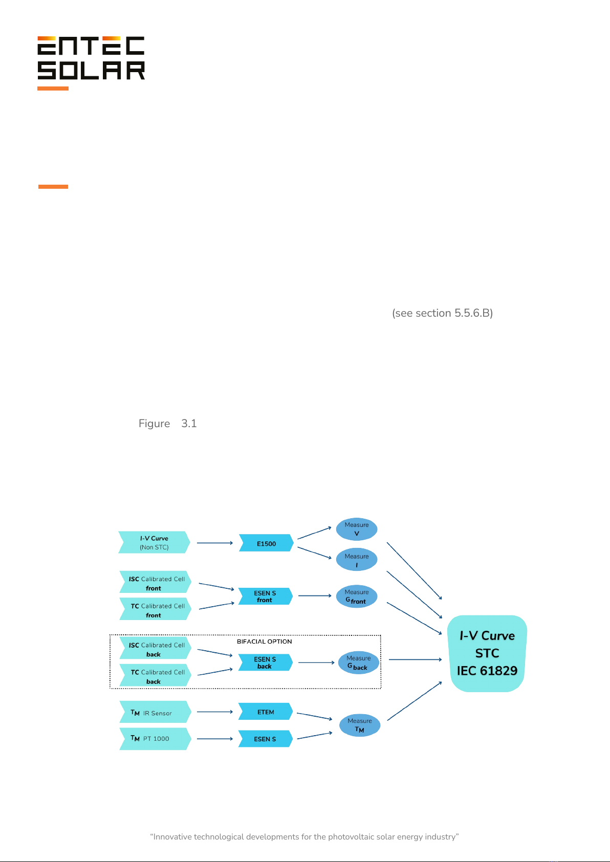
E-Temp devices. Figure 3.1 illustrates the
measured quantities and the processes carried
out to obtain the I-V curve under STC conditions.
To obtain irradiance (G), the E-Sens measures the
short-circuit current (ISC cell) and temperature
(Tc cell) of the calibrated cell and sends these
values to the E-1500 / E-1000. The E-1500
processes these quantities and converts them to
irradiance using the calibration values of the
calibrated cell (see section 5.5.6.B).
To obtain the module temperature1(TM), there
are two options:
- E-Temp: An infrared thermometer designed
by Entec Solar, which allows practical and
non-contact temperature measurement of
various points on the tested element.
- E-Sens: It has up to three channels for the
use of Pt1000 sensors.
1 It's important not to confuse this temperature with the temperature of the cell.
They are different temperatures and are obtained and used differently.
Figure 3.1: Illustration showing the measured quantities, the equipment used, and the procedures carried out
to obtain the curve measured under STC conditions.
“Innovative technological developments for the photovoltaic solar energy industry”

18 www.entecsolar.es
3.2. Operating Conditions
Measuring I-V curves under actual sunlight
requires special care regarding the weather
conditions during the test. Irradiance and module
temperature are the variables that most
significantly affect the final result. Therefore,
special attention must be given to measuring
these variables to obtain accurate and consistent
results. To achieve this, the following precautions
should be taken:
Regarding Irradiance Measurement:
- Conduct measurements during periods of clear
sky throughout the day. If the reference cell and
the tested circuit are exposed to different levels of
irradiance due to factors like passing clouds, the
extrapolation to standard test conditions (STC)
results may not be consistent.
- Ensure coplanarity and proximity between the
reference cell and the tested circuit. Differences in
orientation, tilt, or measured irradiance between
the reference cell and the tested circuit can lead to
inconsistent extrapolations to STC.
- IEC 61829 recommends a minimum irradiance
of 700 W/m2 during measurements. However,
more accurate results are achieved with irradiance
closer to 1000 W/m2.
- Avoid having the angle of solar incidence on the
tested circuit exceed 40°.
Regarding Temperature Measurement:
- Avoid measurements on very windy days. Wind
can cause significant variations between the
actual cell temperature and the measured
temperature, as well as temperature differences
within the tested circuit. In the case of module
chains, wind can cause substantial differences
between end modules and those in the center of
the structure, or between modules in lower and
upper rows. Large temperature differences
between the tested circuit and those measured by
the E-Sens can lead to inconsistent extrapolations
to STC.
- To minimize errors due to temperature
differences within the tested circuit (e.g.,
temperature differences between cells within a
module or between modules in module chains), it
is recommended to measure temperatures at
various points within the tested circuit.
- IEC 61853-1 recommends measuring the
temperature of a module at the three positions
shown in Figure 3.1 and using the average of the
three temperatures for extrapolation to STC. The
E-1000 has been programmed to average up to
three PT-1000 measurements taken with the
E-Sens or to use the average with a user-selected
number of points measured with the E-Temp.
- For temperature measurement in module chains,
it is recommended to measure the temperature of
at least three modules in the chain, using the
three points indicated in Figure 3.2 within each
module. It is advisable to measure a module near
the end of the chain and two modules from the
center of the chain. The use of the E-Temp, which
enables wireless measurements, is highly
recommended for this purpose.
Figure 3.2. Positions for placing temperature
sensors on a photovoltaic module
based on IEC 61853-1.
“Innovative technological developments for the photovoltaic solar energy industry”

19 www.entecsolar.es
4.
Preparation Prior to Measurements
4.1.
First Use of the Device
The E-1500 / E-1000, before being shipped, has
undergone rigorous quality controls during its
production and has been electrically and
mechanically inspected after manufacturing. All
functionalities of the device have been tested, and
every possible precaution has been taken to
ensure the device is delivered without any
damage or operational defects. However, it is
advised to thoroughly examine the device and test
its operation upon receipt and before beginning a
measurement campaign. If any defects or
anomalies in operation are detected, contact Entec
Solar or your nearest distributor immediately.
4.2. Battery Charging
Both the E-1500 / E-1000 and the E-Sens have a
rechargeable lithium-ion battery inside. The
complete device package includes a specific
charger for the E-1000 / E-1500 battery and
another specific charger for the E-Sens. Each
charger has a different type of connector: the
E-1000 uses a Jack connector, and the E-Sens
uses a micro-USB connector. The charging
connector for each device can be seen in Figures
2.3 and 2.6 in sections 2.2.2 and 2.2.3.
By default, both devices are distributed with a
battery charge level of 60%. Before the first use of
the devices, make sure to charge both batteries to
100% to maximize their usage time. With a fully
charged battery, the E-1500 / E-1000 can operate
for more than 8 hours, while the E-Sens can
operate for more than 10 hours.
The E-1500 / E-1000 charger includes an LED
that indicates the charging status. During battery
charging, this LED will be red, and once the device
is fully charged, it will turn green. The E-Sens is
charged using a standard micro-USB cable from
any 5V source, such as a computer USB port or a
mobile phone charger. While the E-Sens is
charging, an LED inside it lights up, located just
above the micro-USB connector and visible from
the outside (See Figure 2.10).
During charging, this LED emits a red light, and
when charging is complete, it emits a green light.
The battery charge status of both devices (E-1500
/ E-1000 and E-Sens) can also be seen in the
top-right corner of their respective screens (Figure
5.3). The indicator displays the charge status in
levels, where each level indicates a specific charge
status (Figure 5.3).
- One red square: charge between 0-10%.
- One white square: charge between 10-25%.
- Two white squares: charge between 25-50%.
- Three white squares: charge between 50-75%.
- Four white squares: charge between 75-100%.
On the E-Sens screen, the actual battery voltage
can also be seen. This value provides a more
accurate representation of the battery's charge
level, where below 3.5V, immediate charging of
the device is recommended.
“Innovative technological developments for the photovoltaic solar energy industry”
20 www.entecsolar.es
2 Para la obtención de los valores de calibración de la célula de referencia consulte el certificado de calibración entregado con su equipo.
The E-1500 / E-1000, before being shipped, has
undergone rigorous quality controls during its
production and has been electrically and
mechanically inspected after manufacturing. All
functionalities of the device have been tested, and
every possible precaution has been taken to
ensure the device is delivered without any
damage or operational defects. However, it is
advised to thoroughly examine the device and test
its operation upon receipt and before beginning a
measurement campaign. If any defects or
anomalies in operation are detected, contact Entec
Solar or your nearest distributor immediately.
Insert the cards into the slots located at the top of
each of the devices (Figures 2.1 and 2.4).
IMPORTANT: The battery charge level is
indicative and depends on various variables, such
as ambient temperature, the rate of device usage,
battery lifespan, manufacturing differences
between batteries, etc. The displayed levels are
approximate and based on a standard battery.
These levels can change over time, causing the
battery to discharge earlier than expected or even
jump between levels more quickly than the
percentages described in this section. As the
device is used, these levels may change, and the
user should be aware of this to avoid running out
of battery during a measurement campaign.
4.3. Memory Card Insertion
The E-1500 and E-1000 store all measured data
on SD cards, while the E-Sens uses a MicroSD
card. Both cards are supplied with the device
shipment. Both devices can function without these
cards, but it will not be possible to store data
without them. In the event of loss or replacement
of the supplied cards, the use of reputable brand
SD cards is recommended to avoid potential data
loss or memory corruption.
4.4. Initial Configuration
The E-1500 / E-1000 has been designed to offer
very simple operation. However, minimal
configuration is required before each
measurement campaign. The following are the
main steps to follow in configuring the E-1500 /
E-1000 before starting a measurement campaign:
1. Set the local time and synchronize it with the
E-Sens (See section 5.5.11.A.).
2. Configure the module and tested generator
characteristics: The E-1500 / E-1000 uses key
electrical characteristics of the tested module
(VOC, ISC, VM, IM, α, β, and NS, provided by the
manufacturer) as well as the generator
configuration (number of modules in series and
parallel) as input parameters to calculate series
resistance and the parameter k, both necessary for
extrapolation to STC according to IEC-61829 (See
section 5.5.4).
3. Configure the irradiance and temperature
sensors2: Set the calibration values of the
reference cell (irradiance sensor) and select the
temperature measurement method (e.g.,
PT-1000, reference module, E-Temp) as detailed
in section 5.2.2.A.
Before each use of the device, ensure that the SD
cards are inserted and functioning properly to be
able to store all measurements
Insert the cards into the slots located at the top of
each of the devices (Figures 2.1 and 2.4).
IMPORTANT: Insertion and removal of the
cards should be done with the devices turned off
to avoid damage to the cards and the possibility of
losing stored data.
IMPORTANT: The format of the cards should
be FAT32.
“Innovative technological developments for the photovoltaic solar energy industry”
Other manuals for E-1500
1
This manual suits for next models
1
Table of contents
Other Entec Solar GPS manuals


