Entec Solar E-1500 User manual

Smart I-V curve tracer
Entec Solar
Quick Start Guide.

2“Innovative technological developments for the solar photovoltaic industry” www.entecsolar.es
Index
1. Important security information......................03
1.1. Symbols used.......................................................04
2. Technical data.................................................... 05
3. External connectors and parts
description...............................................................06
4.General recommendations...............................09
5.Quick start guide................................................09
5.1. Measurement settings and
preparation..................................................................09
5.2. Connections set up.............................................10
6.
Report
generation............................................13
7. Download data to the PC...............................14
8. Common errors and solutions........................15

3 “Innovative technological developments for the solar photovoltaic industry” www.entecsolar.es
1 Important security information
- Read and keep the manual and follow all the instructions stated on it.
- Use the device only on solar photovoltaic installations.
-
Make use of the Personal Protection Equipment (PPE) recommended for electrical
measurements
as
well
as
the
connection
and
disconnection
of
the
electrical
circuit
under test.
-
Disconnect the photovoltaic circuit under test from any other circuit, p.e. inverter, com
-biner box, grounding and other string on parallel before connecting the I-V curve
tracer.
-
Make
sure
that
the
photovoltaic
circuit
does
not
surpass
the
technical
limit
of
the
device used. In the case of E-1000, the limits are 1000V and 20A.
- Never disconnect the measurement wires while performing a measurement.
-
Do
not
perform
measurements
under
moisture
conditions
or
under
the
rain.
Make
sure that no liquid enters inside the device.
-
Do not perform measurements under the presence of gas, explosives or dust in the
environment.
- Protect the wires from the power and measurement, from the damage and pressure.
-
Use the product only with the products and accessories provided or allowed by
the
manufacturer.
IMPORTANT:
Entec Solar does not take any responsibility on the damage to
the device or people due to an incorrect usage of the devices. It is responsibility of
the user to follow all the indications stated on the manual to make a proper use of the
devices.

4 “Innovative technological developments for the solar photovoltaic industry” www.entecsolar.es
1.1. Symbols used
• Double electrical isolation (class of protection II).
i
•Attention, high voltaje, danger of death.
•
Measurement devices can not be treated as wasted, they have to
be
eliminated as electronics
•
Attention danger! Pay attention to the documentation!
This symbol
appears in front of the instructions that need special attention to avoid
damage to materials or people.
•Keep in mind all the documentation attached to the measuring device.
-
In order to improve the quality of the measurements, use the I-V curve tracer only
with the battery. This means, not connected to the power charging cable.
-
Under no conditions open the case of the device. If you do it the warranty will
immediately void.
Dangerous
voltages
may
still
be
present
in
the
equipment
even
after
disconnecting to the test circuit.
-
In order to perform any maintenance operation on the device, make contact with the
technical support of Entec Solar.

5 “Innovative technological developments for the solar photovoltaic industry”
”
www.entecsolar.es
Input voltage range 0-1000 V
Input current range 0.1-20 A
Operating temperature -10 a +65 ºC
Input voltage range 0-1500 V
Input current range 0.1-20A (up to 35A optional)
Operating temperature -10 a +65 ºC
Voltage Inputs Channel for measuring solar radiation MAX 2V
Temperature Inputs 1 x PT-1000 reference cell
3 x PT-1000
Operating temperature -10 a +65 ºC
2 Technical specifications
Specifications E-1500
Specifications E-1000
Specifications E-Sens

6 “Innovative technological developments for the solar photovoltaic industry”
”
www.entecsolar.es
Figure 1.3. Lateral inputs
and their description
2.
Jack connection
for the battery charger
1.
USB input for the
bar code reader
Figure 1.1. Top inputs and their description.
1. SD card slot
2. Negative pole inputs for I-V
curve measurement
3. Positive pole inputs for I-V
curve measurement
Figure 1.2. Frontal inputs and their description
1. Power button
E-1500
ATTENTION: Do not expose the device to direct sunlight for long periods of time
3 External connectors and parts description
2.
5 Inch color touch
screen with a 800x480
resolution

7 “Innovative technological developments for the solar photovoltaic industry” www.entecsolar.es
Figure 2.3. Lateral inputs and their description
1. Jack connection for
the battery charger
2. USB input for the
bar code reader
3. Micro USB input for
SD card access
Figure 2.1. Top inputs and their description.
1. External Antenna SMA connector
2. SD card slot 3. Negative pole inputs for I-V curve measurement
4. Positive pole inputs for I-V curve measurement
Figure 2.2. Frontal inputs and their description
1. Power button
E-1000
ATTENTION: Do not expose the device to direct sunlight for long periods of time
3 External connectors and parts description
2.
5 Inch color touch
screen with a 800x480
resolution
8 “Innovative technological developments for the solar photovoltaic industry” www.entecsolar.es
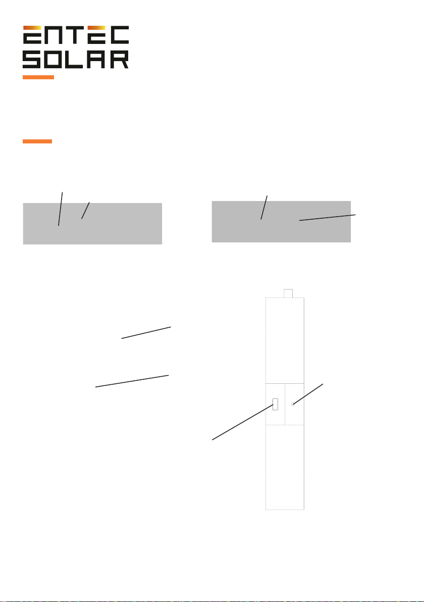
E-Sens
3 External connectors and parts description
ATTENTION: Do not expose the device to direct sunlight for long periods of time
Figure 3.4. Lateral inputs and their description
1. USB input for
a battery charger
2. Charger level
LED indicator
Figure 3.3. Frontal inputs and their description
1. Power button
2. Color screen.
Figure 3.1. Top inputs and their description
1. SMA connector for an external antenna
2. micro SD card slot
Pt1000-3
Figure 3.2. Shows bottom inputs and their description
1. PT1000 Reference cell
2. Reference cell
Pt1000-2
Pt1000-1

9 “Innovative technological developments for the solar photovoltaic industry” www.entecsolar.es
4 General recommendations
5 Quick Start Guide
The interface of the E-1500 / E-1000 is designed based on rectangles as buttons.
You may press the desired button to use the associated function.
There are functions, like for example “Autosave”, that when they are pressed they
change the background to the red color. This means that the function is active. Press
on it again to disable it and the color will change to blue.
When numbers are introduced to set up a parameter, all the gaps must be filled,
even if the value of them are zero.
It is strongly recommended to fully read the manual before proceeding with the mea-
surements and check the corresponding section in case of doubt.
1. Turn on the device.
2. Check that the battery levels of the devices are correct as well as the SD cards are
all in place. (Section 4.2 and 4.3).
3. Place the radiation and temperature sensors in a location that is representative of
the circuit under test and make sure that the calibration cell is on the same plane as
the solar cell. Also make sure you make no shadow on the solar cell.
4. Connect the reference cell, as well as all the PT1000 used to the corresponding
channel inputs.
5. Connect the barcode scanner to the device (optional) (Section 5.5.10)
5.1 Configuration previous to the measurements

10 “Innovative technological developments for the solar photovoltaic industry” www.entecsolar.es
IMPORTANT: Before starting with a new season of measurements, make sure
that the configuration values of the device are properly set up and that they match
the circuit under test.
IMPORTANT: It is mandatory to introduce the values on all the empty gaps,
even if they are zeros.
6.
Adjust date and time, and synchronize with the E-Sens. Select Settings -> Other
->Adjust Date/Time (Section 5.5.11A)
7.
Set up the characteristic module under test (VOC, ISC, VM, IM,
α,
β
y NS).
Settings->
Module
Settings
(Section
5.5.4).
Save
the
configuration
in
a
memory
slot
for
modules (Section 5.5.4.B).
8.
Set up the generator settings (number of modules on series and parallel). Settings
-> Generator settings (Section 5.5.5).
9.
Verify the radiance sensor calibration (reference cell) Settings -> Sensor settings
(Section 5.5.6.A).
10.
Select E-Temp or PT1000 depending on the temperature sensor you want to
use. You can do this on the main screen or inside the sensor settings menu. (Section
5.5.6.B).
11.
Set up the tolerance threshold. For Isc, Voc y Pm. Settings
-> Other ->
Tolerance. (Section 5.5.11.C)
12. Select the file name to store the data. (Section 5.2.2.E)
13.
Select and set up the measurement options (manual measurement, auto
measure,continuous measurement). (Section 5.5.7 5.5.9)
14. Select the saving options (manual save or autosave). (Section 5.5.8)
5.2
Conections set up
Reference cell
The
radiance
sensor
is
a
calibrated
solar
cell
made
out
of
silicon,
that
need
to
be
placed on the same plane as the solar module. It is connected with the E-Sens with
some banana plugs to measure ISC on the 2V connector located on the lower right
part of the device. Additionally, you may connect the PT-1000 of the reference cell
to correct radiance using the temperature measurement of the calibrated cell. These
banana plugs are connected on the lower left side of the device.

11 “Innovative technological developments for the solar photovoltaic industry” www.entecsolar.es
Module or generator
Figure 5. Proper connection to E-1000.
The user must disconnect the test circuit from any other element that it may be
connected. Not doing this may cause serious damage to the device or the test circuit.
Use the cables provided with the device to connect it to the test circuit. It is made out
of two red wires and two black wires that dame a 4-point connection.
First connect the four banana plugs (two red and two black) to the device. The red
color is the positive pole of the test circuit and the black color is the negative pole.
The provided wires have an MC4 ending to direct connect to solar photovoltaic
modules.
The cables provided with the device have been manufactured with the proper mate-
rial to allow to connect them directly. As a result, the positive pole (red wire) has a
female MC4 terminal, and the negative pole (black wire) has a male MC4 terminal.
There is also a special adapter with crocodile endings to connect to other elements,
like for example a bus-bar from a combiner box, if it may be necessary.
IMPORTANT:
A wrong connection of the positive or negative pole of the test
circuit
with
the
device
may
cause permanent
damage
to
the
device.
The
red
color means the positive pole of the test circuit and the black color means
the
negative pole of the test circuit.
ATTENTION:
During these maneuvers there is risk of electrical shock. It is
mandatory to use the personal protection elements to reduce this risk to the
minimum and properly perform the established sequence to disconnect the test
circuit from the rest of the elements.
Figure
4.
Connection of E-1000 to the test circuit.

12 “Innovative technological developments for the solar photovoltaic industry” www.entecsolar.es
IMPORTANT: During the start of the device, it is important to not press seve-
ral times the power on button, and not to press it for too long, as this may turn off the
device.
Curve measurement:
Before starting with this procedure, make sure you follow the steps to configure
and connect the device properly.
Also, it is recommended to perform the measurements with the following conside-
rations:
- Perform the measurements during clear sky and no wind.
-
Make
sure
the
calibrated
cell
is
on
the
same
plane
as
the
modules
of
the
test
circuit without making shadows to it.
- Measure the temperature on different points of the test circuit.
-
Perform the measurements with a radiation level between 800 and 1200 W/m2,
and never under 600 W/m2.
- Avoid an angle of incidence of the sun superior to 40 °.
Temperature measurement:
Temperature
measurement
is
a
process
that
can
be
performed
in
several
ways
(Section 5.5.6.B). Anyway, Entec Solar always recommends to use the E-Temp as
it is faster, easier and more accurate.
To power on the E-Temp, press lightly and only one time the power on button, and
wait a couple of seconds for it to show the start screen. In order to power off the
device, keep pressed the power button for 5 seconds.
On the standby screen, you can perform measurements pressing one time the
power
button located on the center of the device. When you measure an I-V
curve, if you
have the E-Temp selected (Section 5.5.6.B), the device will beep and
a message will
show on screen stating that it is waiting for the E-Temp
temperature measurement.
Perform the temperature measurement to proceed with the measurement.

13 “Innovative technological developments for the solar photovoltaic industry” www.entecsolar.es
Figure 6. An example of temperature
measurement locations within a module according to IEC 61853-1.
6 Report geration
At
the
end
of
the
day,
after
finishing
measuring,
it
is
recommended
to
generate
a
report with all the measurements performed that day.
The report is generated as a ‘.csv’ file and includes the most important values of the
measured curves.
To generate a daily report, you may follow these steps:
1.
Make sure that
all the curves are on the SD card, and that the card is properly
inserted into the device.
2. Inside the Settings menu, press “Report generation”
3. Select the date you wish to create the report.
4.
Press the generate button and wait for it to be generated. Once it is done, it will
be automatically saved to the SD card.
After
performing
the
measurement
the
data
will
show
on
the
screen
for
a
few
seconds. After that, the device will go back to the standby mode.
Keep in mind that the same button is used to power on, measure and power off the
device, so you have to be cautious when pressing it. It is important that you do not
press the button several times or for way too long.
When measuring strings of modules, it is recommended to measure the temperature
of
at
least
three
modules
of
the
string.
One
module
close
to
the
ending
and
two
modules
on
the
enter
of
the
string.
It
is
also
recommended
to
measure
the
sport
indicated in the following picture:

14 “Innovative technological developments for the solar photovoltaic industry” www.entecsolar.es
7 Download data to the PC
In order to obtain the measurement data extracting the SD card of the device follow
these steps:
1. Make sure the device is turned off.
IMPORTANT: The extraction of the SD card with the device turned on, may
cause irreversible damage to the card and permanent loss of the data.
2.
Push lightly the SD card to the inside of the device until you hear *click*. In the case
of the E-Sens it is necessary to use an object that allows to push it to the inside of
the device.
3. Release the pressure and wait for the card to slide out of the slot.
4. Extract the card from the device.
5. Insert the card inside a card reader on your laptop or PC or use a USB card reader.
6. The Pc will detect the inserted card automatically.
7. Open the file explorer on your PC and sear the SD card directory.
8. Copy the files from the card directory to your desired folder
on your computer.
9. Open the files with a spreadsheet program like Excel.

15 “Innovative technological developments for the solar photovoltaic industry” www.entecsolar.es
8 Common errors and solutions
1. Booting your device displays the message “SD card error”:
a. Make sure there is an SD card inserted into the device slot.
b.
If the SD card is absent, turn off the device, insert an SD card and restart the
device.
c. If the error message persists once the card is inserted, try another SD card.
d. If the message persists, contact the technical service.
2.
The radiation value shown in the E1500 / E-1000 device is not correct or it is not
showing anything.
a.
Make
sure
that
there
is
communication
between
E-Sens
and
the
E-1500
/
E-1000. For a proper communication the colour shown in the background of the
radiation has to be yellow or green.
b.
Check
that
the
sensor
configuration
is
properly
set
up.
Select
Settings
->
Sensor
Settings,
and
check
that
the
values
of
Isc
and
Alpha
are
correct.
If
not,
modify them.
c.
If there is no communication, shut down and turn on the device. It may also be an
issue with the distance. Check again with both devices close together and make
sure the antennas are installed properly.
d.
It may also be the case that several E-Sens and E-1500 / E-1000 are working
together in the same place. This may result in noise between the communications.
As
a
result,
you
should
only
use
one
E-Sens,
despite
working
with
several
I-V
curve tracers at the same time.
e.
In
the
situation
that
the
error
still
persists,
please
contact
with
the
technical
service.

16 “Innovative technological developments for the solar photovoltaic industry” www.entecsolar.es
3. The value of the temperatura shown is not correct.
a.
Make
sure
that
there
is
communication
between
E-Sens
and
the
E-1500
/
E-1000. For a proper communication the colour shown in the background of the
radiation has to be yellow or green.
b.
Check
that
the
sensor
configuration
is
properly
set
up.
Select
Settings
->
Sensor
Settings,
and
check
that
the
temperature
mode
selected
is
the
one
you
actually use (PT1000, IR Sens, Mod Ref) and with the proper configuration. Check
the section 5.5.6.B of the manual.
c.
If there is no communication, shut down and turn on the device. It may also be an
issue with the distance. Check again with both devices close together and make
sure the antennas are installed properly.
d.
It may also be the case that several E-Sens and E-1500 / E-1000 are working
together in the same place. This may result in noise between the communications.
As
a
result,
you
should
only
use
one
E-Sens,
despite
working
with
several
I-V
curve tracers at the same time.
e.
In
the
situation
that
the
error
still
persists,
please
contact
with
the
technical
service.
4.
After
pressing
the
button
to
measure,
the
device
beeps
and
does
not
show
the
curve and buttons do not work on the screen.
a.
Check just above the settings button if the E-Temp option is selected. Also check
if there is a message on the screen stating that the device made a measurement
and it is waiting for the temperature value of the E-Temp. If that is the case, the
device is in the standby mode and it is waiting for the E-Temp data to make the
extrapolation
of
the
curve
values
to
continue
measuring.
If
you
do
not
own
an
E-Temp
or
you
do
not
need
to
use
it,
you
have
to
disable
it
inside
the
sensor
settings before starting to measure.
5.
The device does not sabe the barcode scanner data inside the csv files, even if it is
shown on the device screen.
a.
When you are going to make a measurement saving the barcode scanner data,
you have to use the scanner only when the device asks for it through a message on
the screen. Otherwise, if you use the scanner too soon, you will still see the code
on the screen but it will not be saved on the csv file as it will not be associated with
the measurement performed.

“Innovative technological
developments for the solar
photovoltaic industry.”
Contact: contact@entecsolar.es
www.entecsolar.es
Other manuals for E-1500
1
This manual suits for next models
1
Table of contents
Other Entec Solar GPS manuals


