Entec LBS-751 User manual

Version 1.1
Quick Start Guide www.Entec-USA.com
Date: June 2018
LBS-751 Electronic
Sectionalizer Control
Patent Pending Technology

Quick Start Guide
LBS-751 Control
2
www.Entec-USA.com
ENTEC is packaging a new Sectionalizer Control with our Load Break Switch (LBS) featuring an
SEL-751 relay, innovative smart-logic and patent pending technology. Known as LBS-751, this
new unit expands traditional sectionalizer applications and modernizes power system protection.
With three simple setpoints the factory program is push-button-ready. Let’s get started.
Important Documents Inside Cabinet
LBS Routine Test Record
SEL Production Test Report
User Manual
Product Guide
Quick Start
Flash Stick with Factory Docs, acSELerator Application and RDB Template
Computer Setup
1. Copy factory docs, acSELerator Setup file, and RDB from flash stick to laptop. Rename
RDB as desired.
2. Stow away flash stick in a safe place.
3. Install acSELerator using v6.7.0.1 Setup file included. This loads the application and
latest 751 driver. For Step-By-Step acSELerator installation see APPENDIX 1.
(acSELerator and drivers also available online at www.selinc.com)
4. Set comm parameters on laptop: IP 192.168.1.10
Subnet 255.255.255.0
Gateway 192.168.1.1
5. Open acSELerator and go to Tools>Options>Settings
Check the checkbox to enable “Prompt for Action on Settings Read”
751 Setup
6. Choose RDB: click Open, use tool at end of selection box to navigate and open RDB
Template then click Cancel to close window.
7. Connect to 751 with standard ethernet cable. Set IP on communications configuration in
acSELerator to 192.168.1.2.
8. Select “Read From” and enter Level-One password when prompted: OTTER
9. Read prompt will pop-up with options. Select “Open Settings with Editor”.
10. Save settings as OEM file, name as desired (e.g. “Customer Field Device OEM”).
11. Re-Read from 751 a second time. When prompt window appears make sure to select
(highlight) “LBS-751 SVN-007 Template” and then select option to merge from relay
template. When template view appears save file as “LBS-751 SVN-007 Template v1.0”
12. Program setpoints, save and send to 751.
Phase Pickup, Ground Pickup, Operations. Enter relay name if desired
13. Set Time and Date: use HMI => Control Window while connected 751
Scada Setup
14. See APPENDIX 2
Congratulations … All Done
Quick Start Guide APPENDIX 1
LBS-751 Control
3
www.Entec-USA.com
APPENDIX 1
Install acSELerator Application
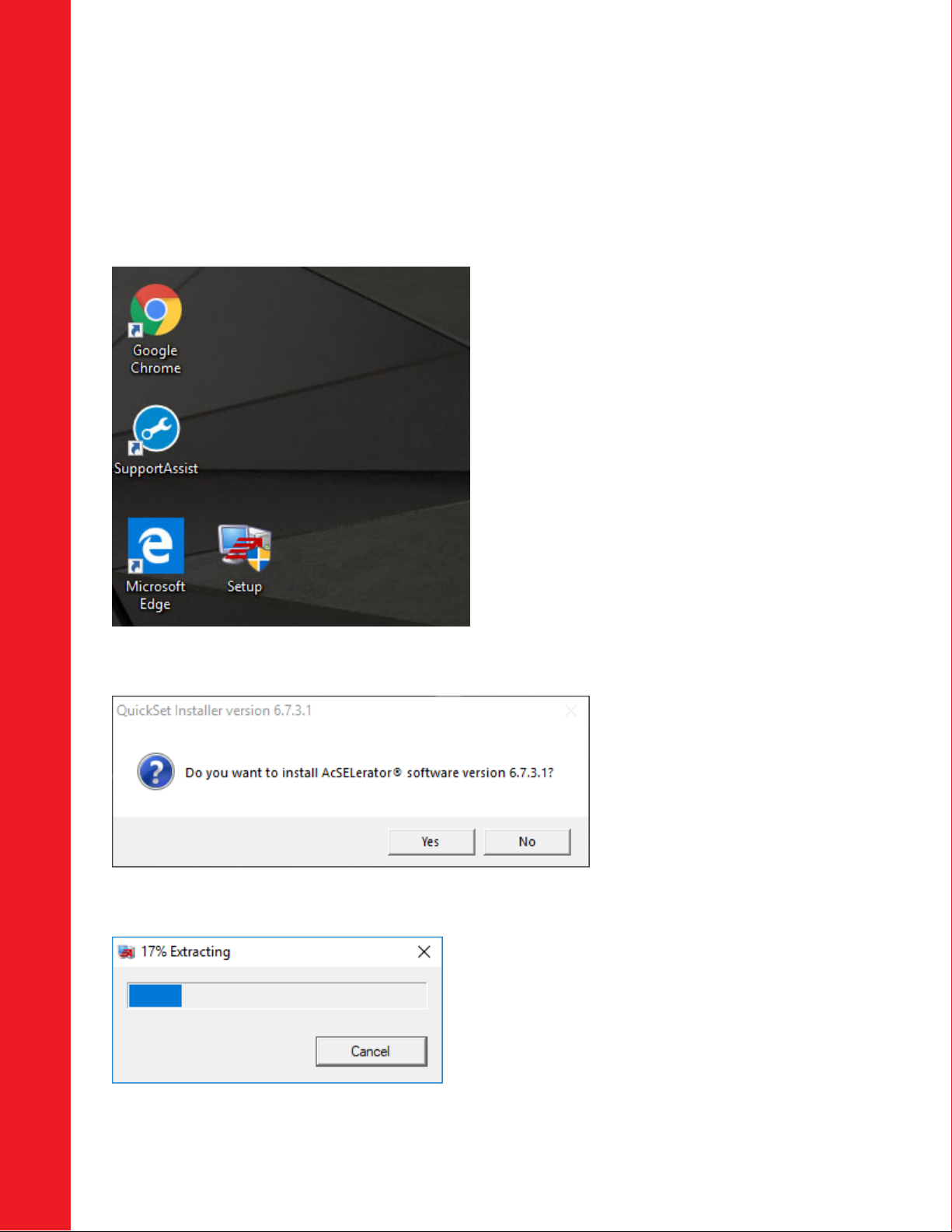
SAVEINSTALLATIONFILEONDESKTOPTHENDOUBLE‐CLICKTOSTARTINSTALL
AFTERDOUBLECLICKINGTHISWINDOWAPPEAR
AFTERCLICKINGYES

Quick Start Guide APPENDIX 1
LBS-751 Control
4
www.Entec-USA.com
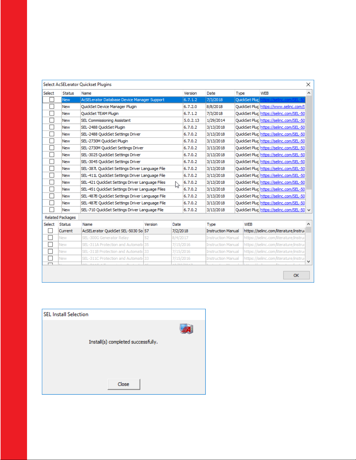
AFTEREXCTRACTIONISCOMPLETE.CHECKBOXESAREGRAYED‐OUT…CLICKOK.
LICENSEAGREEMENTAPPEARSNEXT.CLICK“IAGREE”TOCONTINUE.

Quick Start Guide APPENDIX 1
LBS-751 Control
5
www.Entec-USA.com
AFTERYOUAGREETHISWINDOWAPPEARS.SELECT“IAGREE”AGAIN.
THISWINDOWAPPEARSNEXT,TAKESABOUT2‐3MINUTETOINSTALL

Quick Start Guide APPENDIX 1
LBS-751 Control
6
www.Entec-USA.com
AFTERINSTALLTHISWINDOWAPPEARSLISTINGDRIVERSFORALLSELRELAYS.YOUHAVETHECHOICE
TOUNCHECKBUTTHEEASIESTOPTOINISCLICKOK.
AFTERYOUCLICKOKPROGRESSWINDOWAPPEARSWHILEINSTALLINGALLTHEDRIVERS.THISTAKESA
COUPLEOFMINUTESTOINSTALL
Quick Start Guide APPENDIX 1
LBS-751 Control
7
www.Entec-USA.com
AFTERINSTALLINGDRIVERS,THISWINDOWISNEXT.CLICKOKTOPROCEED.
AFTERCLICKINGOK,THISWINDOWISNEXT.INSTALLATIONCOMPLETE.

Quick Start Guide APPENDIX 2
LBS-751 Control
8
www.Entec-USA.com
APPENDIX 2
Scada Setup
Port Settings
1. Open RDB with acSELerator and select OEM file saved previously in Step 4. Save-As
OEM Comm Config (e.g. Customer Field Device OEM Comm Config).
2. Use setting editor to open Port config. Make changes, save and upload new Port
settings to 751.
Quick Tip
Make sure to enable a session in either Modbus or DNP protocol when using Port 1
(Ethernet), scroll down to the bottom of Port 1 page.

Quick Start Guide APPENDIX 2
LBS-751 Control
9
www.Entec-USA.com
Modbus User-Defined Assignment Map
Boolean Points
StatusBits SourceLocation
02hRead 03hRead
Tag WordMap Bit
Coil
UserTable Address Bit
BreakerClosed(52A) IN302 Row18 6 150 MOD_040
165 6
BreakerOpen(52B) IN303 Row18 5 149 MOD_040
165 5
HandleLock(69) IN301 Row18 7 151 MOD_040
165 7
DiagnosticAlarm T03_LED Row38 3 307 MOD_044
169 3
BatteryFail T04_LED Row38 2 306 MOD_044
169 2
ACPowerFail T05_LED Row38 1 305 MOD_044
169 1
Polarity: Logic 1 = True Condition

Quick Start Guide APPENDIX 2
LBS-751 Control
10 www.Entec-USA.com
Analog Points
SpecialAnalogValues SourceLocation 03hRead
Tag Scaler UserTable Address DataType
Operations MV01 0.01 MOD_001 126 32BitSigned
PhasePU(Amps) MV02 0.01 MOD_003 128 32BitSigned
GroundPU(Amps) MV03 0.01 MOD_005 130 32BitSigned
TripCounter SC03 1 MOD_065 190 16Bit
Control Points
ControlBits SourceLocation 05hForceSingleCoil
Tag CoilAddress DataType
PB01–LockPushButtons RB01 27 RemoteBitCoil
PB02–LoopModeEnable RB02 28 RemoteBitCoil
PB03–CLOSESwitch RB03 29 RemoteBitCoil
PB04–TRIPSwitch RB04 30 RemoteBitCoil
TargetReset RB05 31 RemoteBitCoil
TripCountReset RB06 32 RemoteBitCoil
ResetMax/Min RB07 33 RemoteBitCoil
Polarity: Logic 1 = Active Condition (Set Coil)
Modbus Protocol Codes
02h Read Input Status (Coils) Command
Use function code 02h to read bits as individual coil values. The coil method increases data
size and may require multiple polls to completely read one device, but single binary values
placed in one coil greatly simplifies binary state determinations at the Scada master. Use
the 02h coil address provided in the status bit table above to collect data.
Bytes Field
02hReadrequestformatfromMaster
1byte SlaveAddress
1byte FunctionCode(02h)
2bytes CoilAddress
2bytes Numberofcoilstoread(n)
2bytes CRC‐16
02hSuccessfulresponseformatfromSlave
1byte SlaveAddress
1byte FunctionCode(02h)
1byte Coilsofdata(n)
nbytes Data
2bytes CRC‐16

Quick Start Guide APPENDIX 2
LBS-751 Control
11 www.Entec-USA.com
03h Read Holding Register Command
Use function code 03h to read holding register values containing “bit words” or analog data.
To determine data address, add 125 (decimal) to Setting location in the Modbus User-
Defined Assignment Map above.
Example 1: Phase-A Current Demand (IAD) is available using the 03h function to
read address 133 (Mod_08 Setting location + 125 = 133).
Example 2: AC Power Fail is available using the 03h function to read address 169 as
noted in the Status Bit table above. AC Power Fail can be determined from the state of bit 1
using polarity convention where Logic 1 = True Condition. The Scada master will typically
collect 16 bits (2 Bytes) from address 169. The desired bit location is determined counting
from Right to Left starting with Bit-0. The second bit counting from the right is Bit-1
representing AC Power Fail. (1 = AC Power Fail True, 0 = False).
Bytes Field
03hReadrequestformatfromMaster
1byte SlaveAddress
1byte FunctionCode(03h)
2bytes Startingregisteraddress
2bytes Numberofregistersread(n)
2bytes CRC‐16
03hSuccessfulresponseformatfromSlave
1byte SlaveAddress
1byte FunctionCode(03h)
1byte Bytesofdata(n)
nbytes Data(2‐250Bytes)
2bytes CRC‐16
03h command will collect all data from the LBS-751 User-Defined Assignment Map with a
single poll (125 registers). In many systems this method will collect Binary and Analog
points with a single poll allowing more devices to communicate with the Scada master.
Large Scada systems utilize 03h to collect binary words versus using 02h to retrieve single
binary bits.

Quick Start Guide APPENDIX 2
LBS-751 Control
12 www.Entec-USA.com
Modbus Protocol Codes, continued
05h Force Single Coil Command
Use function code 05h to set and clear a coil. Remote bit coil will track the binary state
value forced with the 05h function. State value “1” will Set remote bit coil and “0” will Clear
the coil. Refer to Control Point table for coil assignments and address.
Example 1: Apply “Push Button Lock” with 05h function using Scada to force coil
address 27. Set Logic “1” for three seconds then clear to Logic “0” operates Button Lock
same as pressing PB1 directly on the front panel.
Bytes Field
05hForceSingleCoilformatfromMaster
1byte SlaveAddress
1byte FunctionCode(05h)
2bytes CoilReference
1byte OperationCode(FF=Set;00=Clear)
1byte Placeholder
2bytes CRC‐16
For additional information about Modbus commands and a comprehensive data map refer to the
SEL 751 user manual Appendix E: Modbus Communications. A PDF copy is included on the
flash stick located inside the control cabinet or available online at www.selinc.com.
SEL ® is a registered trademark of Schweitzer Engineering Laboratories, Inc. (SEL)


