Helios SU-3 10 User manual

Dreistufen-Schalter 10 V/0-10 V
Three-Step Switch 10 V/0-10 V
Interrupteur à trois étages 10 V / 0-10 V
SU-3 10
SA-3 10
mit zusätzlichem Anschluss für Wochenzeitschaltuhr
with additional connection for weekly timer
avec raccordement supplémentaire pour minuterie
hebdomadaire
Helios Ventilatoren
BEDIENUNGSANLEITUNG
OPERATING INSTRUCTIONS
MODE D´EMPLOI
EN
FR
DE

DEUTSCH

Dreistufen-Schalter SU/SA
Bedienungsanleitung
2
1.0 Wichtige Informationen
Zur Sicherstellung einer einwandfreien Funktion und zur eigenen Sicherheit sind alle
nachstehenden Vorschriften genau durchzulesen und zu beachten. Nationale einschlägi-
gen Normen, Sicherheitsbestimmungen und Vorschriften (z.B. DIN EN VDE 0100) sowie
die TAB des EVUs sind unbedingt zu beachten und anzuwenden.
Die Bedienungsanleitung als Referenz am Gerät aufbewahren. Nach der Endmontage
muss dem Betreiber (Mieter/Eigentümer) das Dokument ausgehändigt werden.
1.1 Warn- und Sicherheitshinweise
Nebenstehendes Symbol ist ein sicherheitstechnischer Warnhinweis. Alle Sicher-
heitsvorschriften bzw. Symbole müssen unbedingt beachtet werden, damit jeg-
liche Gefahrensituation vermieden wird.
1.2 Garantieansprüche – Haftungsausschluss
Wenn die nachfolgenden Ausführungen nicht beachtet werden, entfällt unsere Gewähr-
leistung. Gleiches gilt für Haftungsansprüche an den Hersteller. Der Gebrauch von Zu-
behörteilen, die nicht von Helios empfohlen oder angeboten werden, ist nicht statthaft.
Eventuell auftretende Schäden unterliegen nicht der Gewährleistung.
1.3 Vorschriften – Richtlinien
Bei ordnungsgemäßer Installation und bestimmungsgemäßem Betrieb entspricht das
Produkt den zum Zeitpunkt seiner Herstellung gültigen Vorschriften und CE-Richtlinien.
1.4 Sendungsannahme
Die Lieferung enthält den Dreistufen-Schalter SU-3 10 oder SA-3 10 für Unterputz bzw.
Aufputzmontage inkl. Anschlusskabel.
Die Sendung ist sofort bei Anlieferung auf Beschädigungen und Typenrichtigkeit zu
prüfen. Falls Schäden vorliegen umgehend Schadensmeldung unter Hinzuziehung des
Transportunternehmens veranlassen. Bei nicht fristgerechter Reklamation gehen evtl.
Ansprüche verloren.
1.5 Einlagerung
Bei Einlagerung über einen längeren Zeitraum sind zur Verhinderung schädlicher Ein-
wirkungen folgende Maßnahmen zu treffen:
Schutz durch trockene, luft- und staubdichte Verpackung (Kunststoffbeutel mit Trocken-
mittel und Feuchtigkeitsindikatoren). Der Lagerort muss erschütterungsfrei, wasser-
geschützt und frei von übermäßigen Temperaturschwankungen sein. Schäden, deren
Ursprung in unsachgemäßem Transport, unsachgemäßer Einlagerung oder Inbetrieb-
nahme liegen, sind nachweisbar und unterliegen nicht der Gewährleistung.
1.6 Einsatzbereich – Anwendung
Der Dreistufen-Schalter ist für Unter- oder Aufputzmontage vorgesehen. Zur dreistufi-
gen Ansteuerung von EC-Ventilatoren oder Frequenzumrichtern, mit einem 0-10 V DC
Steuereingang.
Ein bestimmungsfremder Einsatz ist nicht zulässig!
1.7 Funktionen
– Auswahl über 3-stufigen Betriebsschalter (manuell, Stufe 1-3) innerhalb des gesamten
Kennlinienfeldes
– Ansteuerung von EC-Ventilatoren oder Frequenzumrichtern, mit einem 0-10 V DC Steu-
ereingang
– Steuerspannung direkt am Bedienelement messbar
– Zur Realisierung einer weiteren Betriebsstufe, z.B. Nachtbetrieb, optional um Wochen-
zeitschaltuhr (WSUP/WSUP-S, Zubehör) ergänzbar.
KAPITEL 1
ALLGEMEINE
HINWEISE
m
ACHTUNG m
DE

Dreistufen-Schalter SU/SA
Bedienungsanleitung
3
DE
2.0 Funktionen
Über den Dreistufen-Schalter können drei verschiedene Sollwertvorgaben ausgegeben
werden. Jede Stufe (S1-S3) ist über ein eigenes Potentiometer frei von (...siehe Tabelle
unten) Volt einstellbar (mit Kreuzschlitzschraubendreher, Ø 3 mm).
Zusätzlich ist der Anschluss einer Wochenschaltuhr (WSUP, WSUP-S, Zubehör) zur
Umschaltung von 3-Stufen Tagbetrieb auf z.B. Nachtbetrieb möglich. Der Nacht-/Ab-
senkbetrieb ist über ein weiteres Potentiometer (A1) ebenfalls frei von 0 bis 10 V DC
einstellbar.
Es dürfen nur EC-Ventilatoren oder Frequenzumrichter angeschlossen werden,
die mind. 1,5 mA bei 10 V Versorgung zur Verfügung stellen (Eigenverbrauch Be-
dienteil).
Gesamtstrom = Eigenverbrauch (Bedienteil) + Ventilator-Bürdenstrom
(Bürdenstrom abhängig von der Bürde des 0-10 V Eingangs des Ventilators)
Alle drei Potentiometer S1, S2 und S3 sind im Lieferzustand auf Linksanschlag gestellt.
Die Potentiometer sind auf die örtlichen Erfordernisse einzustellen.
2.1 Einstellbereich der Schaltstufen
Der Dreistufen-Schalter SU / SA verfügt über 4 Potentiometer:
KAPITEL 2
FUNKTIONEN
ACHTUNG m
HINWEIS!
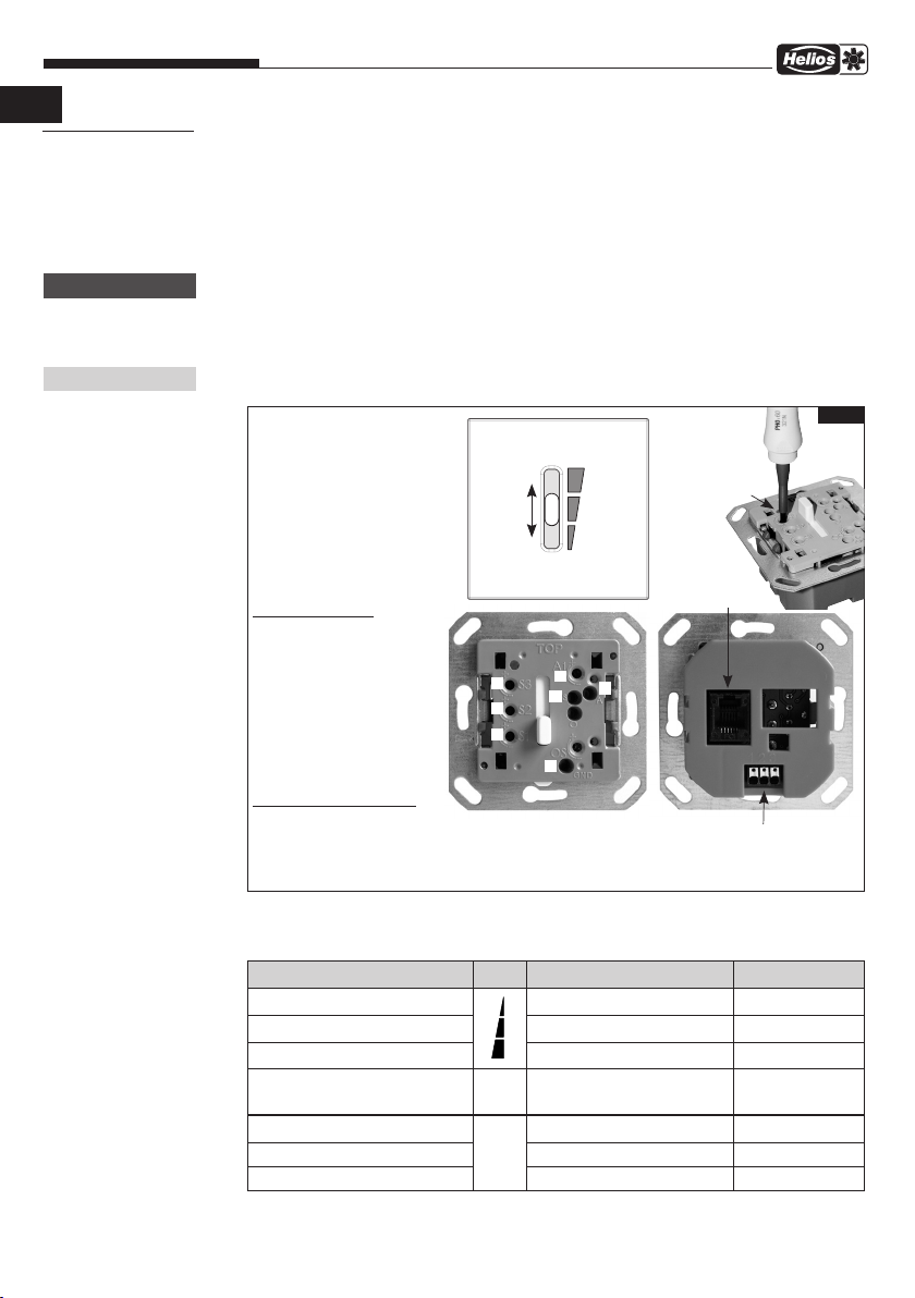
ò ù
òSchiebeschalter
ù Skala Stufe S1-S3
Potentiometer:
ò Stufe S1
ù Stufe S2
ä Stufe S3
ë „A1“
ö „S“ (Messpunkt)
ü „A“ (Messpunkt)
Å „GND“ (Masse)
TIPP: Spannungsmessung:
Über GND und S kann die Aus-
gangsspannung des Zuluftven-
tilators in der eingestellten Be-
triebsstufe gemessen werden.
ò
ù
äë
ö
Å
ü
Potentiometer-
justierung,
òbis ë
Abb.1
GND / 1 2 3
Brücke auf Klemme 2/3
Werkseinstellung,
siehe SS-1022)
RJ12
Steuerleitung
Bezeichnung Skala Bezeichnung Einstellbereich
S1 Stufe 1 des Zuluftventilators 0 bis 10,0 V
S2 Stufe 2 des Zuluftventilators 0 bis 10,0 V
S3 Stufe 3 des Zuluftventilators 0 bis 10,0 V
A1 Stufe für WSUP
oder Nachtabsenkung
0 bis 10,0 V
GND Masse -
SSpannung Schiebeschalter Messpunkt
ASpannung externer Befehl Messpunkt

Dreistufen-Schalter SU/SA
Bedienungsanleitung
4
DE
2.2 Elektrischer Anschluss
Vor allen Wartungs- und Installationsarbeiten ist das Gerät allpolig vom Netz zu
trennen! Der elektr. Anschluss darf nur von einer autorisierten Elektrofachkraft durch-
geführt werden.
Die einschlägigen Sicherheitsvorschriften, Normen (VDE 0100 und VDE 0700 sowie die
TAB‘s der EVU‘s und UVV) sind einzuhalten. Ebenso ist die Montage- und Betriebsvorschrift
des Ventilators zu beachten.
2.3 Technische Daten
SU-3 10
Für Unterputz-Montage, Einbau in tiefe UP-Dose (T 65 mm)
Versorgung Eingang 10 V DC Ri=12,5 kOhm
(Sicherheitskleinspannung)
Eigenverbrauch 1,5 mA
Steuerausgang 0 bis 10 V DC
wahlweise über Schalter
oder externe Umschaltung
Schutzart IP30 (eingebaut)
Schutzklasse III
Maße mm B 80 x H 80 x T 15 überst.
Schaltplan SS-1022
Best.-Nr. 4266
SA-3 10
Für Aufputz-Montage
Versorgung Eingang 10 V DC Ri=12,5 kOhm
(Sicherheitskleinspannung)
Eigenverbrauch 1,5 mA
Steuerausgang 0 bis 10 V DC
wahlweise über Schalter
oder externe Umschaltung
Schutzart IP30 (eingebaut)
Schutzklasse III
Maße mm B 80 x H 80 x T 60
Schaltplan SS-1022
Best.-Nr. 4267
2.3 Prinzipschema
In Abhängigkeit der anzuschließenden Ventilatortype können ggf. mehrere Ventilatoren
parallel an einen Dreistufen-Schalter angeschlossen werden.
ACHTUNG m
HINWEIS!
Abb.2

Dreistufen-Schalter SU/SA
Bedienungsanleitung
5
3.0 Schaltplan SS-1022
KAPITEL 3
SCHALTPLAN
WSUP,
Art.Nr. 9990
L
N
S1
S2
S3 A1
Potentiometer
Sollwertvorgabe:
S1 = 0-10 V
S2 = 0-10 V
S3 = 0-10 V
A1 = 0-10 V
SU/A-3 10
Art.Nr. 4266/7
Brücke auf Klemme
Sollwert
1/2
2/3
Festwert Poti A1
-
Schalterbetrieb,
Poti S1 - S3
-
RJ12
Buchse
123
16
+
-
10 V
GND / 0 V
0 - 10 V
123
16
Schalterbetrieb Schalterbetrieb mit
Nachtabsenkung
230V~
SS-1022 Nr. 85264 001 25.02.16
optional
Aus = 0 V
WSUP-S,
Art.Nr. 9577
S1
S2
S3
Adapter:
RJ12-Litze
SU/A-3 10
Art.Nr. 4266/7
16
1
6
sw
or
ge
Farbcode nach IEC 757
BK-sw-schwarz-black
OG-or-orange-orange
YE-ge-gelb-yellow
RJ12
Buchse
+
-
10 V
GND / 0 V
0 - 10 V
optional
Aus = 0 V
Adapter:
RJ12-Litze
16
1
6
sw
or
ge
Farbcode nach IEC 757
BK-sw-schwarz-black
OG-or-orange-orange
YE-ge-gelb-yellow
DE

Dreistufen-Schalter SU/SA
Bedienungsanleitung
6
Notizen:
DE

ENGLISH

Three-Step Switch SU/SA
Operating Instructions
2
1.0 Important information
In order to ensure complete and effective operation and for your own safety, all of the
following instructions should be read carefully and observed. The relevant national stan-
dards, safety regulations and instructions (e.g. DIN EN VDE 0100) as well as the technical
connection conditions of the energy supply company must be observed and ap-
plied.
Keep the operating instructions close to the unit for easy reference. After the final assem-
bly, the document must be issued to the operator (tenant/owner).
1.1 Warning and safety instructions
The adjacent symbol is a safety-relevant warning symbol. All safety regulations
and/or symbols must be absolutely adhered to, so that any dangerous situation is
avoided.
1.2 Warranty claims – Exclusion of liability
Our warranty shall not apply if the following instructions are not observed. The same
applies for liability claims against the manufacturer. The use of accessories, which are
not recommended or offered by Helios, is not permitted. Any damage that may occur is
not liable for warranty.
1.3 Regulations - Guidelines
If the product is installed correctly and used to its intended purpose, it conforms to all
applicable regulations and CE guidelines at its date of manufacture.
1.4 Receipt
The delivery contains the Three-Step Switch SU-3 10 or SA-3 10 for flush-mounting or
surface-mounting incl. connection cable.
Please check delivery immediately on receipt for accuracy and damage. If damaged,
please notify the carrier immediately. In case of delayed notification, any possible claim
may be void.
1.5 Storage
When storing for a prolonged time, the following steps are to be taken to avoid damaging
influences:
Protection by dry, air-dustproof packing (plastic bags with drying agent and moisture
indicators). The storage place must be waterproof, vibration-free and free of temperature
variations. Damages due to improper transportation, storage or commissioning must be
verified and are not liable for warranty.
1.6 Area of application – Application
The Three-Step Switch is intended for flush or surface-mounting. For the three-step
control of EC fans or frequency inverters, with a 0-10 V DC control input.
Any other use than the intended use is prohibited!
1.7 Functions
– Selection via 3-step operating switch (manual, step 1-3) within the entire characteristic
curve diagram
– Control of EC fans or frequency inverters, with a 0-10 V DC control input
– Control voltage directly measurable on operating element
– Weekly timer (WSUP/WSUP-S, accessories) can be added to realise an additional
operating mode, e.g. night mode.
CHAPTER 1
GENERAL
INFORMATION
m
ATTENTION m
EN
Three-Step Switch SU/SA
Operating Instructions
3
EN
2.0 Functions
Three different setpoint settings can be issued via the three-step switch. Each step
(S1-S3) is freely adjustable via a separate potentiometer from (...see table below) Volts
(with a Phillips type screwdriver, Ø 3 mm).
The connection of a weekly timer (WSUP, WSUP-S, accessories) for switching from
3-step daytime mode to e.g. night mode is also possible. The night/reduction mode is
freely adjustable via an additional potentiometer (A1) from 0 to 10 V DC.
Only EC fans or frequency inverters, which provide at least 1.5 mA with 10 V power
supply (controller internal consumption), may be connected.
Total current = Internal consumption (controller) + fan load current
(load current depends on load of 0-10 V fan input)
All three potentiometers S1, S2 and S3 are set to left stop when delivered.
The potentiometers must be adjusted to local requirements.
2.1 Switching step adjustment range
The Three-Step Switch SU / SA has 4 potentiometers:
CHAPTER 2
FUNCTIONS
ATTENTION m
NOTE!
ò ù
òSlide switch
ù Scale Step S1-S3
Potentiometers:
ò Step S1
ù Step S2
ä Step S3
ë “A1”
ö “S” (Meas. point)
ü “A” (Meas. point)
Å “GND” (Earth/Ground)
TIP: Voltage measurement:
The output voltage of the supply
air fan in the set operating mode
can be measured via GND and S.
ò
ù
äë
ö
Å
ü
Potentiometer
adjustment,
òto ë
Fig.1
GND / 1 2 3
Bridge to terminal 2/3
factory setting,
see SS-1022)
RJ12
Control line
Designation Scale Designation Adjust. range
S1 Step 1 of supply air fan 0 to 10.0 V
S2 Step 2 of supply air fan 0 to 10.0 V
S3 Step 3 of supply air fan 0 to 10.0 V
A1 Step for WSUP
or night mode
0 to 10.0 V
GND Earth/Ground -
SVoltage Slide switch Measurem. point
AVoltage External command Measurem. point

Three-Step Switch SU/SA
Operating Instructions
4
EN
2.2 Electrical connection
Before any maintenance or installation work or before opening the terminal compart-
ment, the device must be fully isolated from the power supply. The electrical connec-
tion must be carried out only by a qualified electrician in accordance with the follo-
wing wiring diagram.
The relevant safety regulations, standards (VDE 0100 and VDE 0700 as well as the technical
connection conditions of the local electricity supply companies and accident prevention regu-
lations) must be observed. The Installation and Operating Instructions for the fan must also
be observed.
2.3 Technical data
SU-3 10
For flush mounting, installation in deep FM box (D 65 mm)
Power supply Input 10 V DC Ri=12.5 kOhm
(safety extra-low voltage)
Internal consumption 1.5 mA
Control output 0 to 10 V DC
optional via switch
or external switching
Protection category IP30 (installed)
Protection class III
Dimensions mm W 80 x H 80 x D 15 protr.
Wiring diagram SS-1022
Ref. no. 4266
SA-3 10
For surface mounting
Power supply Input 10 V DC Ri=12.5 kOhm
(safety extra-low voltage)
Internal consumption 1.5 mA
Control output 0 to 10 V DC
optional via switch
or external switching
Protection category IP30 (installed)
Protection class III
Dimensions mm W 80 x H 80 x D 60
Wiring diagram SS-1022
Ref. no. 4267
2.3 Basic circuit diagram
Depending on the fan type to be connected, multiple fans may be connected to a three-
step switch in parallel.
ATTENTION m
NOTE!
Fig.2
EC
fan
Three-step
speed switching

Three-Step Switch SU/SA
Operating Instructions
5
3.0 Wiring diagram SS-1022
CHAPTER 3
WIRING DIAGRAM
WSUP,
Art.Nr. 9990
L
N
S1
S2
S3 A1
Potentiometer
Sollwertvorgabe:
S1 = 0-10 V
S2 = 0-10 V
S3 = 0-10 V
A1 = 0-10 V
SU/A-3 10
Art.Nr. 4266/7
Brücke auf Klemme
Sollwert
1/2
2/3
Festwert Poti A1
-
Schalterbetrieb,
Poti S1 - S3
-
RJ12
Buchse
123
16
+
-
10 V
GND / 0 V
0 - 10 V
123
16
Schalterbetrieb Schalterbetrieb mit
Nachtabsenkung
230V~
SS-1022 Nr. 85264 001 25.02.16
optional
Aus = 0 V
WSUP-S,
Art.Nr. 9577
S1
S2
S3
Adapter:
RJ12-Litze
SU/A-3 10
Art.Nr. 4266/7
16
1
6
sw
or
ge
Farbcode nach IEC 757
BK-sw-schwarz-black
OG-or-orange-orange
YE-ge-gelb-yellow
RJ12
Buchse
+
-
10 V
GND / 0 V
0 - 10 V
optional
Aus = 0 V
Adapter:
RJ12-Litze
16
1
6
sw
or
ge
Farbcode nach IEC 757
BK-sw-schwarz-black
OG-or-orange-orange
YE-ge-gelb-yellow
EN

Three-Step Switch SU/SA
Operating Instructions
6
Notes:
EN

FRANÇAIS

Interrupteur à trois étages SU/SA
Mode d’emploi
2
1.0 Informations importantes
Il est important de bien lire et suivre l’ensemble des consignes suivantes pour le bon
fonctionnement de l’appareil et pour la sécurité des utilisateurs. Les normes nationales,
les conditions de sécurité et les réglementations (DIN EN VDE 0100 par ex.) ainsi que les
conditions techniques de raccordement de la société d’approvisionnement en électricité
sont à respecter et à appliquer impérativement.
Garder la notice à proximité de l’appareil. Après le montage final, le document doit être
remis à l’exploitant (locataire/propriétaire).
1.1 Mises en garde
Les symboles ci-contre indiquent une consigne de sécurité. Toutes les consignes
de sécurité ainsi que les symboles doivent impérativement être respectés pour
éviter tout danger !
1.2 Demande de garantie – Réserves du constructeur
Si les consignes suivantes ne sont pas respectées, la garantie s’annule. Idem pour les
réserves constructeur. L'utilisation d'accessoires non conseillés ou proposés par Helios
n'est pas permise. Les dégâts causés par cette mauvaise utilisation ne sont pas inclus
dans la garantie.
1.3 Réglementations – Normes
Ce produit est conforme aux directives CE en vigueur le jour de sa fabrication et sous
réserve d’une utilisation appropriée.
1.4 Réception de la marchandise
L’emballage contient l’interrupteur à trois étages SU-3 10 ou SA-3 10 pour montage
encastré ou apparent et son câble de raccordement.
Dès réception, vérifier l’état et la conformité du matériel commandé. En cas d’avaries,
des réserves doivent être portées sur le bordereau du transporteur. Elles doivent être
précises, significatives, complètes et confirmées par lettre recommandée au transporteur.
Attention, le non-respect de ces procédures peut entraîner le rejet de la réclamation.
1.5 Stockage
Pour un stockage de longue durée et pour éviter toute détérioration préjudiciable, il
convient de se conformer aux instructions suivantes :
protéger avec un emballage sec, étanche à l’air et à la poussière (sac en matière
synthétique contenant des sachets déshydrateurs et un indicateur d’humidité). stocker
le matériel dans un endroit abrité de l’eau, exempt de vibrations et de variations de
températures excessives. Les dégâts dus à un transport non conforme, un stockage
inadéquat ou une mauvaise installation ne sont pas couverts par la garantie.
1.6 Domaines d'utilisation – Utilisation
L’interrupteur à trois étages est prévu pour pouvoir être monté encastré ou apparent. Il
permet de commander les ventilateurs EC ou variateurs de fréquence selon trois niveaux,
avec une entrée de commande de 0-10 V DC.
Tout usage inapproprié n’est pas autorisé !
1.7 Fonctions
– Sélection via le commutateur à 3 étages (manuel, étages 1-3) au sein d'une même
courbe caractéristique
– Commande des ventilateurs EC ou variateurs de fréquence, avec une entrée de
commande de 0-10 V DC
– Tension de commande directement mesurable sur l’élément de commande
– Permet d’ajouter des étages supplémentaires, par ex. mode nuit, en option une
minuterie hebdomadaire (WSUP/WSUP-S, accessoires) peut être ajoutée.
CHAPITRE 1
GÉNÉRALITÉS
REMARQUES
m
ATTENTION m
FR

Interrupteur à trois étages SU/SA
Mode d’emploi
3
FR
2.0 Fonctions
L’interrupteur à trois étages permet de mettre en place trois valeurs de consigne
prédéfinies différentes. Chaque étage (S1-S3) peut être réglé librement via un
potentiomètre dédié à partir de (...voir tableau ci-dessous) volts (avec un tournevis
cruciforme, Ø 3 mm).
Par ailleurs, un raccordement permet d’ajouter une minuterie hebdomadaire (WSUP,
WSUP-S, accessoires) pour commuter du mode jour à 3 étages au mode nuit par
exemple. Le mode nuit/abaissement nocturne peut également être réglé librement via
un potentiomètre (A1) supplémentaire, de 0 à 10 V DC.
Seuls les ventilateurs EC ou variateurs de fréquence disposant d’une alimentation
d’au moins 1,5 mA à 10 V peuvent être raccordés (consommation propre de la
pièce de commande).
Courant total = consommation propre (pièce de commande) + courant de charge du
ventilateur (le courant de charge dépend de la charge de l’entrée 0-10 V du ventilateur)
Les trois potentiomètres S1, S2 et S3 sont fournis tournés vers la gauche. Les
potentiomètres doivent être réglés en fonction des besoins sur place.
2.1 Plage de réglage des étages de l’interrupteur
L’interrupteur à trois étages SU/SA dispose de 4 potentiomètres :
CHAPITRE 2
FONCTIONNALITÉS
ATTENTION m
REMARQUE !
ò ù
òInterrupteur coulissant
ù Échelle Étages S1-S3
Potentiomètres :
ò Étage S1
ù Étage S2
ä Étage S3
ë «A1»
ö «S» (point de mesure)
ü «A» (point de mesure)
Å «GND» (masse)
ASTUCE : Mesure de la tension :
Via GND et S, il est possible de
mesurer la tension de sortie du
ventilateur soufflage dans l’étage
paramétré.
ò
ù
äë
ö
Å
ü
Réglage des
potentiomètres,
òà ë
Fig.1
GND / 1 2 3
Pont sur les bornes 2/3
Réglage d'usine,
voir SS-1022)
RJ12
Câble de commande
Désignation Échelle Désignation Plage de réglage
S1 Étage 1 du ventilateur soufflage 0 à 10,0 V
S2 Étage 2 du ventilateur soufflage 0 à 10,0 V
S3 Étage 3 du ventilateur soufflage 0 à 10,0 V
A1 Étage pourWSUP
ou abaissement nocturne
0 à 10,0 V
GND Masse -
STension interrupteur coulissant Point de mesure
ATension commande externe Point de mesure

Interrupteur à trois étages SU/SA
Mode d’emploi
4
FR
2.2 Raccordement électrique
Avant tout travail de maintenance et d’installation, l'appareil doit être mis hors-
tension ! Le raccordement électrique ne peut être effectué que par un électricien agréé.
Les règles de sécurité et normes (VDE 0100, VDE 0700, et les conditions techniques de
raccordement de la société d’approvisionnement en électricité et de l’ordonnance sur la prévention
des accidents) applicables doivent être respectées. La notice de montage et d’utilisation du
ventilateur doit également être respectée.
2.3 Données techniques
SU-3 10
Pour montage encastré, montage dans la boîte d’encastrement
UP inférieure (T 65 mm)
Entrée d’alimentation 10 V DC Ri=12,5 kOhm
(basse tension de sécurité)
Consommation propre 1,5 mA
Sortie de commande 0 à 10 V DC
au choix via l’interrupteur
ou commutation externe
Degré de protection IP30 (intégrée)
Indice de protection III
Dimensions en mm B 80 x H 80 x T 15
en dépassement
Schéma électrique SS-1022
Réf. 4266
SA-3 10
Pour montage apparent
Entrée d’alimentation 10 V DC Ri=12,5 kOhm
(basse tension de sécurité)
Consommation propre 1,5 mA
Sortie de commande 0 à 10 V DC
au choix via l’interrupteur
ou commutation externe
Degré de protection IP30 (intégrée)
Indice de protection III
Dimensions en mm B 80 x H 80 x T 60
Schéma électrique SS-1022
Réf. 4267
2.3 Schéma de principe
En fonction du type de ventilateur à raccorder, il peut être possible de raccorder plusieurs
ventilateurs en parallèle à un même interrupteur à trois étages.
ATTENTION m
REMARQUE !
Fig. 2

Interrupteur à trois étages SU/SA
Mode d’emploi
5
3.0 Schéma électrique SS-1022
CHAPITRE 3
SCHÉMA
ÉLECTRIQUE
WSUP,
Art.Nr. 9990
L
N
S1
S2
S3 A1
Potentiometer
Sollwertvorgabe:
S1 = 0-10 V
S2 = 0-10 V
S3 = 0-10 V
A1 = 0-10 V
SU/A-3 10
Art.Nr. 4266/7
Brücke auf Klemme
Sollwert
1/2
2/3
Festwert Poti A1
-
Schalterbetrieb,
Poti S1 - S3
-
RJ12
Buchse
123
16
+
-
10 V
GND / 0 V
0 - 10 V
123
16
Schalterbetrieb Schalterbetrieb mit
Nachtabsenkung
230V~
SS-1022 Nr. 85264 001 25.02.16
optional
Aus = 0 V
WSUP-S,
Art.Nr. 9577
S1
S2
S3
Adapter:
RJ12-Litze
SU/A-3 10
Art.Nr. 4266/7
16
1
6
sw
or
ge
Farbcode nach IEC 757
BK-sw-schwarz-black
OG-or-orange-orange
YE-ge-gelb-yellow
RJ12
Buchse
+
-
10 V
GND / 0 V
0 - 10 V
optional
Aus = 0 V
Adapter:
RJ12-Litze
16
1
6
sw
or
ge
Farbcode nach IEC 757
BK-sw-schwarz-black
OG-or-orange-orange
YE-ge-gelb-yellow
FR

Interrupteur à trois étages SU/SA
Mode d’emploi
6
Notes :
FR

Service und Information
DHELIOS Ventilatoren GmbH + Co KG · Lupfenstraße 8 · 78056 VS-Schwenningen FHELIOS Ventilateurs · Le Carré des Aviateurs · 157 avenue Charles Floquet · 93155 Le Blanc Mesnil Cedex
CH HELIOS Ventilatoren AG · Tannstrasse 4 · 8112 Otelfingen GB HELIOS Ventilation Systems Ltd. · 5 Crown Gate · Wyncolls Road · Severalls Industrial Park ·
AHELIOS Ventilatoren · Postfach 854 · Siemensstraße 15 · 6023 Innsbruck Colchester · Essex · CO4 9HZ
www.heliosventilatoren.de
Als Referenz am Gerät griffbereit aufbewahren!
Please keep this manual with the unit for reference!
Conserver la notice à proximité de l’appareil! Druckschrift-Nr. 82 217-001/0518
This manual suits for next models
1
Table of contents
Languages:
Other Helios Switch manuals


