entegris IntelliGen LV Guide
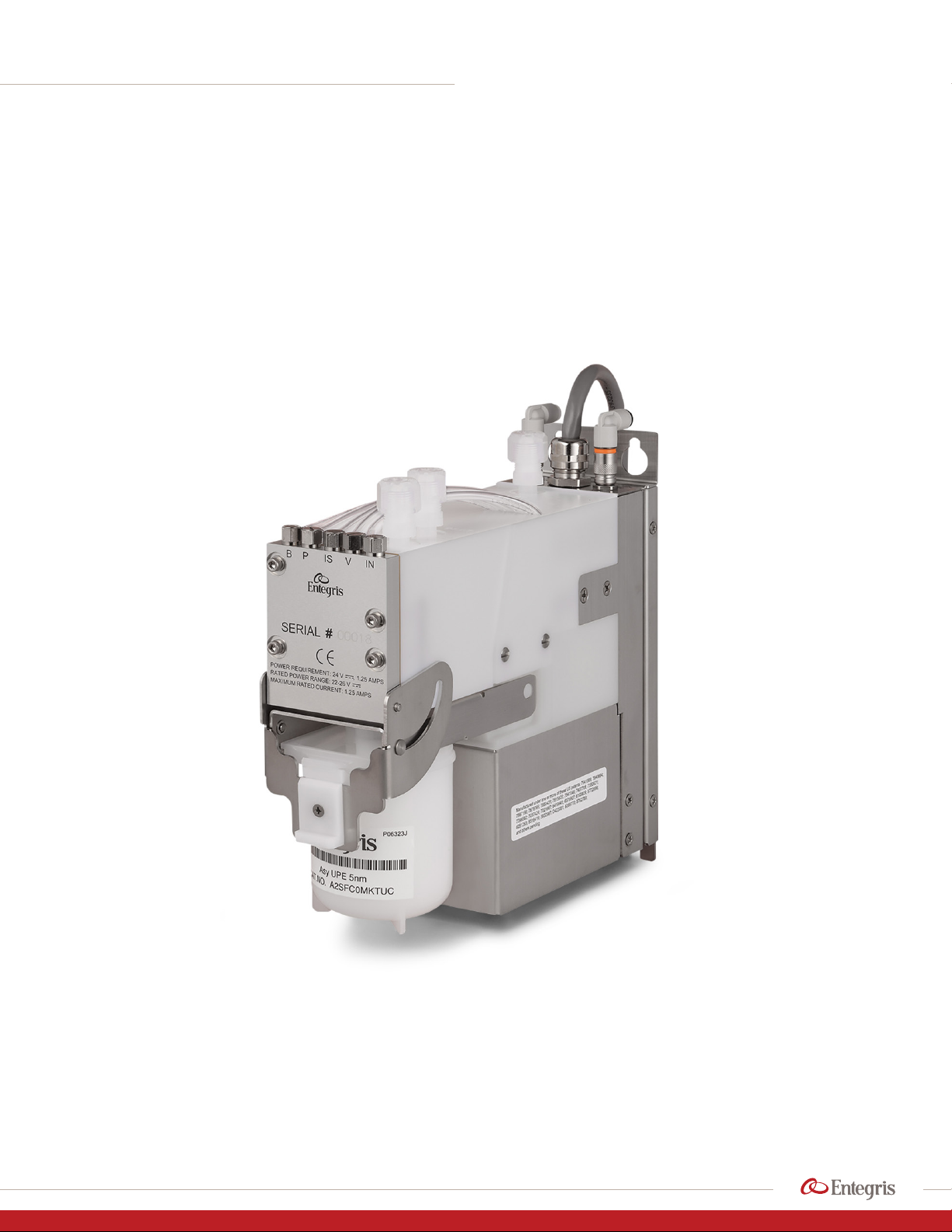
IntelliGen®LV
Dispense System
Installation and use manual
ADVANCED MATERIALS HANDLING |MANUAL

INTELLIGEN LV DISPENSE SYSTEM
1Installation and Use Manual | Entegris, Inc.
TABLE OF CONTENTS
—
Overview ......................................................................... 2
Liability Ownership .......................................................... 2
General Manual Notes .................................................. 2
Changes to the Manual ................................................ 2
Intended Audience ........................................................ 2
Intended Scope and Use ............................................. 2
Safety ............................................................................... 3
Registration for Safety Updates ................................. 3
Contacting the Supplier with Emergency
Health Issues ................................................................... 3
Handling ........................................................................... 4
Chemical Leaks .............................................................. 4
Specifications ................................................................ 6
Compatibility ................................................................... 7
System Overview .......................................................... 8
Appearance ....................................................................... 8
Two-stage Technology Operating Principle ........... 9
Quick Filter Changeout .............................................. 10
Installation .................................................................... 11
Handling .......................................................................... 11
Facility Requirements .................................................. 11
Tools and Materials ...................................................... 11
Installing the Pump ..................................................... 12
Storage ........................................................................... 14
MMI Software ............................................................... 14
Installing Software ....................................................... 14
Connect Tab ................................................................. 15
System Tab .................................................................... 17
Priming Tab ................................................................... 18
Status Tab ...................................................................... 21
Alarms Tab ..................................................................... 23
Recipe Tab ..................................................................... 24
Recharge Tab ................................................................ 24
Utility Tab ....................................................................... 24
Info Tab .......................................................................... 25
Self Test Tab .................................................................. 25
Profiling Tab .................................................................. 25
Confirmation Tab ......................................................... 27
Maintenance ................................................................ 32
Changing the Filter ...................................................... 32
Flushing the System .................................................... 33
Updating the Firmware .............................................. 34
Troubleshooting ........................................................... 35
Appendix: Priming Recipe Information .................... 37
Manufacturing Information ...................................... 38
Product Warranties .................................................... 38
Limited Warranty ........................................................ 39
For More information ................................................ 39
Terms and Conditions of Sale .................................. 39

2
INTELLIGEN LV DISPENSE SYSTEM
Installation and Use Manual | Entegris, Inc.
OVERVIEW
—
Entegris, Inc. provides this information for end
user reference.
Prior to using this manual, the user should verify
with the product manufacturer that the user has
the most recent copy of the product manual.
This manual is owned by Entegris, Inc., an aliated
company for its suppliers, and the title shall not pass
to the user as a result of the use of the manual.
LIABILITY OWNERSHIP
—
Read the following carefully before continuing:
In no event shall Entegris or its suppliers be liable for
any damages whatsoever (including, without limita-
tion, damages for loss of business profits, business
interruption, loss of business information, or any
pecuniary loss) arising out of the use of or inability to
use this manual, even if Entegris has been advised of
the possibility of such damages.
GENERAL MANUAL NOTES
—
CHANGES TO THE MANUAL
The manufacturer reserves the right to make changes
to the product covered in this manual to improve
performance, reliability, or manufacturability.
Although every eort has been made to ensure ac-
curacy of the information contained in this manual,
the manufacturer assumes no responsibility for
inadvertent errors. Contents of the manual are
subject to change without notice.
INTENDED AUDIENCE
This manual is intended for technicians involved in
semiconductor manufacturing, and assumes that
each individual is familiar with the proper handling
of photochemicals and other potentially hazardous
materials. Users must also be familiar with installing
and using software on a computer running the
Windows®operating system.
INTENDED SCOPE AND USE
This manual is intended to be used by experienced
technicians for the planning, installation, and operation
of the described system. This manual contains basic
safety information for the installation and use of the
pump system. This manual covers this system only.
MISHANDLING products exposed to
a hazardous substance may result in death or
serious injury. Always follow the recommenda-
tions and guidelines provided by the chemical
suppliers and manufacturers. Always wear
appropriate personal protective equipment
(PPE) as required for the chemicals in use. Refer
to the Material Safety Data Sheets (MSDS) for
each chemical.
INTELLIGEN LV DISPENSE SYSTEM
3Installation and Use Manual | Entegris, Inc.
SAFETY
—
DANGER! Failure to follow these safety instruc-
tions may lead to fire, electric shock, chemical
exposure, or other injuries, or damage to pro-
perty. Read all safety information before usage.
REGISTRATION FOR SAFETY UPDATES
The manufacturer requests that the user notifies
the manufacturer of equipment installation, usage
and status, and provides appropriate contact informa-
tion for safety alerts and information regarding the
system. Please register usage with a local Entegris
service center.
CONTACTING THE SUPPLIER WITH
EMERGENCY HEALTH ISSUES
Please contact the manufacturer with any emergency
safety and health concerns.
WARNING! Safety is designed into every
product. When followed, these minimum
guidelines provide an acceptable level of
safety for operating and maintaining the
system but are not a substitute for deter-
mining internal safety procedures.
Failure to comply with the safety precautions or
warnings indicated in this manual violates the
safety standards that form a part of the intended
use of this equipment. The manufacturer assumes
no liability for the user’s failure to comply with
these requirements.
WARNING! Use of controls, adjustments, or
procedures other than those specified in this
manual without consulting a competent safety
professional may result in exposure to potential
hazards. Always follow established industrial
safety practices when operating the equipment.
CAUTION! End of life statement. De-commission-
ing of the system, or any part of the system shall
be in a manner that is consistent with appropriate
regulations and guidelines.
WARNING! Chemicals are not supplied with this
equipment. Refer to the chemical supplier’s
MSDS for specific health and safety information.
WARNING! POTENTIAL CHEMICAL LEAK! Use
one set of O-rings only. Check that the filter has
O-rings or the manifold has O-rings. NEVER use
O-rings on both the filter and the manifold or the
system may leak chemical.
WARNING! PINCH HAZARD! Keep
fingers clear of jaw mechanism to
prevent personal injury.
WARNING! PINCH HAZARD! Pump
weight in excess of 15.0 kg (33 lbs).
Use care in lifting and carrying the
pump to prevent personal injury.
WARNING! Wear chemical-resistant garments
and eye protection while changing the filter
and during start-up. Use additional PPE as
directed by facility safety personnel, the MSDS,
or chemical safety guidelines.
CAUTION! Only technically qualified personnel
should install the equipment.
CAUTION! DO NOT use this equipment in any
manner not specified by the manufacturer. If
the equipment is used in a manner other than as
specified in this document, the safety protections
may be impaired.
CAUTION! Fittings and components
damage easily; handle all components
with extreme care. DO NOT scratch or
over-tighten any component.
CAUTION! EQUIPMENT DAMAGE HAZARD! Turn
o power before connecting or disconnecting
any cable to the device, or damage may occur.

4
INTELLIGEN LV DISPENSE SYSTEM
Installation and Use Manual | Entegris, Inc.
HANDLING
Each dispense system is manufactured with
strict assembly, test, and inspection processes
to ensure high-quality assembly and protection
from unintended chemical release. As with all
chemical handling systems, the dispense system
has chemical connection points that must be
handled with care, including:
• Fluid ports on the top surface
• Filter fittings
• Pressure sensor ports on the back (under the
top cover)
• Between valve plate (front) and pump block
• Pump diaphragm mechanism in the pump block
A potential for chemical leak can occur at the above
cited points. Use care to ensure that O-rings are either
on the filter or on the manifold, never on both, or the
system will leak. Refer to filter installation instructions
in this manual.
Do not loosen any screws on the mechanism unless
specifically directed to do so by an Entegris service
engineer. Handle the dispense system with care to
prevent damage to any fluid handling point.
Additional points of critical assembly and perfor-
mance include pneumatic tubing, pressure and
vacuum connecting points, and solenoid manifold
tubes (inside cover or backplane). Use care to pre-
vent any damage to the unit which could result in
chemical leakage.
CHEMICAL LEAKS
In the event of a suspected or confirmed chemical
leak from the pump or in the vicinity of the pump,
please follow the instructions below:
1. Determine chemical currently in use with pump.
2. Obtain MSDS.
a. Determine if any incompatible materials may
come in contact with the leaking material.
b. Isolate incompatibles with barriers, including
spill containment, closing valves and removing
the chemical supply, if it is safe to do so.
c. Identify appropriate chemical protection equip-
ment requirements, including gloves, face and
eye protection, and chemical protective clothing
to prevent exposure to or contact with chemicals.
d. Determine if the chemical has permissible
exposure limits or short-term exposure limits:
– Identify limits requiring respiratory protection.
– Ensure that appropriate monitoring devices
are available to measure air levels.
3. Only personnel properly trained to clean spills
of hazardous materials should conduct cleanup
activities. Consult local authorities or identified
hazardous materials emergency response agen-
cies or contractors for assistance if the facility
does not have trained personnel for spill cleanup
or containment.
4. Ensure adequate monitoring and protective
equipment is available for cleanup of hazardous
materials.

INTELLIGEN LV DISPENSE SYSTEM
5Installation and Use Manual | Entegris, Inc.
5. Obtain supplies for cleanup and containment
compatible with the chemical.
6. Obtain compatible containers to collect spilled
material and cleanup materials.
7. Ensure adequate ventilation is provided before
opening cabinet or equipment where a buildup of
vapors could occur. If flammable chemical is in use:
a. Monitor area for flammable levels with appropri-
ate monitoring devices.
b. Isolate all power sources or potential sources
of sparks.
c. Use intrinsically safe tools and monitoring
equipment.
8. Isolate pump from power sources to prevent fluids
from flowing through unit during cleanup of leak
or spill.
a. Use appropriate lockout/tagout procedures to
de-energize unit.
b. De-energize all areas of unit that may be in
contact with spilled or leaking material.
c. When disconnecting nitrogen and/or any
pressurized gas, wear appropriate PPE gloves,
then close the facility gas supply to prevent
gas release when disconnecting lines.
9. If spilled chemical is within equipment, wipe all
surfaces carefully with wipes appropriate for the
chemical.
10.If chemical is contained in the tubing or the pump,
provide collection container under the lines or
pump during removal to collect chemical and
prevent additional spills.
11. Decontaminate surfaces with appropriate decon-
tamination materials per recommendation of
chemical manufacturer.
12.Contain cleanup materials, contaminated debris,
and equipment.
13.Dispose of materials in accordance with local,
state, and national regulatory requirements.
14. Provide any required service to the equipment and
verify all spilled material is collected and cleaned
from surfaces.
15.Replace any equipment and secure lines in
accordance with normal maintenance and
service requirements.
16.Confirm air levels are safe.
17. Return equipment to service per standard
procedures.

6
INTELLIGEN LV DISPENSE SYSTEM
Installation and Use Manual | Entegris, Inc.
SPECIFICATIONS
—
Dispense performance Volume 0.01–10.0 mL in 0.001 mL increments
Rate 0.01 – 3.0 mL/sec in 0.001 mL/sec increments
Repeatability ≤
0.02 mL 3 sigma
Viscosity range* 1–100 cP or at higher viscosities when dispense pressure
does not exceed 29 psi
Maximum dispense
design pressure**
0.20 MPa (29 psi)
Recharge performance Fill rate, filtration rate,
vent rate, purge rate
0.1–3.0 mL/sec in 0.001 mL/sec increments
Vent frequency Auto-venting or 1–10,000 dispense cycles
Mechanical Wetted surfaces Modified PTFE, PTFE, Kalrez®
Connection type Insert style, Super Type Pillar®, or Flowell™60 Series
Filter Impact®8G or Impact 2 V2 (OF style)
Inlet, outlet and
vent tubing
OD: 6.35 mm (0.25") or 6.0 mm (0.24")
ID: 3.97 mm (0.156") or 4.0 mm (0.16")
Inlet gas type Regulated N2
Operating conditions Minimum operating pneumatic pressure: 0.26 MPa (38 psi)
Maximum operating pneumatic pressure: 0.28 MPa (40 psi)
Pneumatic leak pressure: 0.30 MPa (43 psi)
Vacuum -68 kPa (20 in-Hg min)
Dimensions Height 200.1 mm (7.878")
Width 60.7 mm (2.39")
Depth 209.17 mm (8.235")
Weight Approximately 5 kg (11 lbs)
Electrical Current rating 1.25A maximum
Input voltage (system) 24 VDC ±10%
Serial communication Specifications are dependent on interface module use
Parallel communication Triggers and acknowledgments
Certifications See provided documentation
Environment Indoor use only
Altitude below 2000 m (2187.22 yd)
Ambient temperature 5°– 40°C (41° –104°F)
Maximum relative humidity 80% for temperatures up to 31°C (88°F) decreasing linearly
to 50% relative humidity at 40°C (104°F)
Main supply fluctuations from 22–26 VDC
Transient overvoltages of overvoltage category II
Pollution degree 2
* Depends on tool configuration. Contact applications support for detailed window of operation.
** Maximum pressure is a limit on the Window of Operation. Actual volumes and rates may be restricted
to comply with the pressure limits for a given viscosity, tubing diameter, tubing length, and tubing height.

INTELLIGEN LV DISPENSE SYSTEM
7Installation and Use Manual | Entegris, Inc.
COMPATIBILITY
The IntelliGen®dispense system has been optimized
for the dispense of photoresists and other photo-
chemicals. The system is uniquely designed to deliver
highly accurate dispenses even at very low volumes
with high repeatability.
The internal wettable surfaces of the dispense system
are PTFE, modified PTFE, and Kalrez.
The following is a partial list of compatible solvents.
Please contact Entegris for compatibility of a specific
solvent that is not included in the list.
Acetone
Adamantane (tricyclodecane)
n-Amyl acetate
Anisole (methyl phenyl ether,
methoxybenzene)
2-Butoxyethanol (ethylene glycol
monobutyl ether, butyl cellosolve)
n-Butyl acetate
Butyl alcohol
Butyl cyclohexane
Butyl ether (dibutyl ether)
Cyclopentanone
Cyclohexanone
Developer (positive, 0.26N TMAH)
Diacetone alcohol
DI water
Dichloromethane
(methylene chloride)
Diethyl maleate
DIGLYME
(diethylene glycol dimethyl ether)
Dimethyl acetamide
Dimethyl cyclohexane
Dimethyl maleate
Dimethyl sulfoxide
1,3-Dioxolane
(glycol methylene ether)
EEP (ethyl 3-ethoxypropionate)
ECA, EEA, EGMEA (cellosolve
acetate)
Ethanone (2,2-dimethoxy-
1,2-diphenyl, dimethoxy
phenylacetophenone)
Ethyl acetate
Ethyl acetyl acetate
(ethyl acetoacetate)
Ethyl alcohol
Ethyl benzene
Ethyl cyclohexane
Ethyl lactate
Ethyl malonate (diethyl malonate,
malonic ester)
Ethyl pyruvate
Gamma butyrolactone
2-Heptone (methyl amyl ketone)
Hexane
2-Hexanone (methyl butyl ketone,
propylacetone)
HMDS (hexamethyldisilazane)
Hexamethyldisiloxane
1,6-hexanediol diacrylate
2-hydroxy-2-methylpropiophenone
IPA (isopropyl alcohol, 2-propanol)
Isoamyl acetate
Isobutyl ketone (2,6-dimethyl-4-
heptanone, diisopropylacetone)
MCA (methyl cellosolve acetate,
2-methoxyethyl acetate)
Mesitylene (1,3,5 trimethylbenzene)
Methyl acetate (methyl acetic ester)
Methyl alcohol
Methyl ethyl ketone (2-butanone)
2-Methoxy-1-propanol
(monopropylene glycol
methyl ether)
MIBK (methyl isobutyl ketone,
4-methyl-2-pentanone)
Mineral oil
Mineral spirits
MMP (methyl 3-methoxypropionate)
Morpholine
NMP (N-methyl pyrrolidinone)
Octamethyltrisiloxane
Orthodichlorobenzene
(1,2-dichlorobenzene)
2-Pentanone (methyl propyl ketone)
Petroleum spirits (petroleum ether)
PGE (propylene glycol monoethyl
ether, 1-ethoxy-2-propanol)
PGME (propylene glycol
monomethyl ether,
1-methoxy-2-propanol)
PGMEA (propylene glycol
monomethyl ether acetate,
1-methoxy-2-propyl acetate)
PGPE (propylene glycol propyl
ether, 1-propoxy-2-propanol)
2-Propenamide
(N,N-dimethylacrylamide)
2-Propenoic acid
Propyl alcohol
Tetrahydrofuran
Trichloroethylene
2.5% TMAH (tetramethyl ammonium
hydroxide) in DI water
Toluene
Xylene

8
INTELLIGEN LV DISPENSE SYSTEM
Installation and Use Manual | Entegris, Inc.
SYSTEM OVERVIEW
—
APPEARANCE Communications/
power cable
Vacuum
inlet
Pressure
inlet
Fluid
inlet
Vent
Fluid
outlet
Top View
6.35 mm
(0.25")
Back View
38.0 mm
(1.50")
60.7 mm
(2.39")
8.00 mm
(0.25”")
Front View
Side View
209.2 mm (0.23")
9.80 mm
(0.39")
216.5 mm (0.52")
2.0 mm (0.08")
7.50 mm
(0.29")
62.0 mm
(2.44")
60.7 mm
(2.29")
200.1 mm
(7.88")
200.1 mm
(7.88")
189.5 mm
(7.46")
INTELLIGEN LV DISPENSE SYSTEM
9Installation and Use Manual | Entegris, Inc.
TWO-STAGE TECHNOLOGY OPERATING PRINCIPLE
The IntelliGen dispense system uses a proven, unique
two-stage design to operate dispense and filtration
functions independently. Filtration occurs at a reduced
rate, which prevents microbubble formation and
maximizes filter performance.
The system uses two motors (one for fill and one for
dispense) and advanced fluid paths to deliver extreme
repeatability at dispense rates down to 0.1 mL/sec.
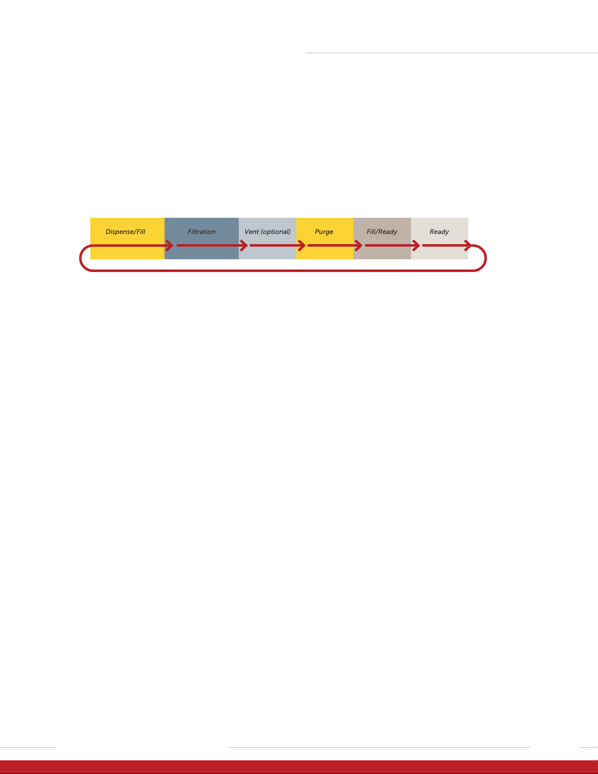
During normal operation, the dispense system
cycles through the dispense/fill, filtration, vent,
purge, fill/ready, and ready states.
1. READY State
– The inlet, external outlet, vent, and purge valves
are closed.
– The isolate and barrier valves remain open for
a time to allow the system to reach ambient
pressure, then the valves close.
– The dispense chamber is full of fluid and is ready
to dispense.
2. DISPENSE/FILL State
– The external valve opens as the dispense
motor pushes fluid through the outlet and
onto the wafer.
– The dispense rate and volume are motor-
controlled and independent of the fill and
filtration rate.
– Simultaneously during dispense, the inlet valve
opens and begins filling the inlet chamber.
3. FILTRATION State
– The isolate and barrier valves open and the
fill motor pushes fluid through the filter and
into the dispense chamber as the dispense
motor retracts.
– At the programmed filtration rate, the dispense
chamber fills with filtered fluid.
4. VENT State
– The barrier valve closes and the vent valve opens.
– The fill motor pushes fluid and bubbles upstream
of the filter membrane through the vent port.
5. PURGE State
– The barrier valve closes as the purge valve opens
and the dispense motor pushes fluid out of the
dispense chamber to the inlet source. This step
ensures that the dispense fluid contains no
bubbles.
6. FILL/READY State
– The dispense chamber is full of fluid and ready
to dispense.
10
INTELLIGEN LV DISPENSE SYSTEM
Installation and Use Manual | Entegris, Inc.
QUICK FILTER CHANGEOUT
Patented Connectology®allows start-to-finish filter
changes in under a minute. No tools are required,
no photochemical to clean up, and there is minimal
personnel exposure to potentially hazardous volatile
organic compounds (VOCs). Additionally, the dispense
system uses a patented two-stage technology that
provides rapid priming of the filter, resulting in signi-
ficant chemical savings.
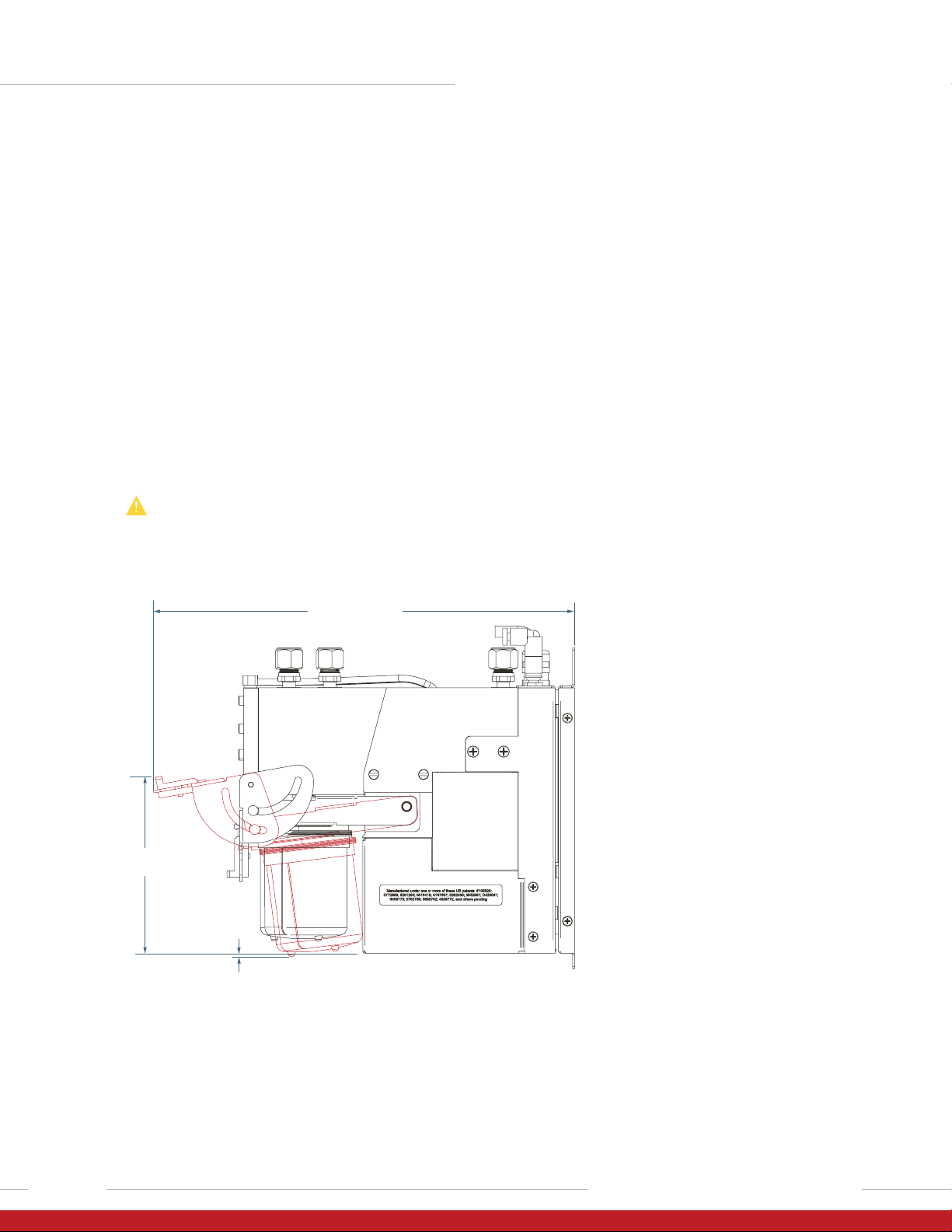
The following diagram shows the absolute minimum
required clearances for filter replacement (filter jaw
clearance highlighted in red). The filter can be placed
in the service area, then slid into the manifold. This
feature allows easy installation into tight areas with
drip trays, etc., below the equipment.
CAUTION! DRIP HAZARD! If the pump has been
installed with minimum changeout space, use
appropriate wipes, caps, and/or other materials
to prevent spilling of fluid from the filter during
changeout.
2.10 mm
(0.08”)
262.3 mm (10.33”)
109.5 mm
(4.31”)
INTELLIGEN LV DISPENSE SYSTEM
11Installation and Use Manual | Entegris, Inc.
INSTALLATION
—
This section covers the site requirements, tools, and
equipment to install the system. Technical support is
available for all installation types.
NOTE: All components are shipped in protective packaging
to prevent damage during transport. If damage is found,
please file a damage claim with the transportation carrier
and contact customer support immediately.
CAUTION! Avoid particulate contamination. Do
not unwrap any cleanroom-packaged item until
immediately before installation.
WARNING! Only technically qualified personnel
should install the system. Wear chemical-resis-
tant garments and eye protection. Chemicals
are not supplied with this equipment. Obtain
a chemical MSDS for each chemical used with
the system and follow all safety requirements.
CAUTION! Fittings and components
damage easily; handle them with
extreme care. Do not scratch or
over-tighten any part.
HANDLING
Use care when lifting and carrying the pump. The
pump weighs in excess of 5 kg (11 lbs), has blunt
edges, and can cause pinch or other personal injuries.
WARNING! PINCH HAZARD! Pump
weight in excess of 5 kg (11 lbs). Use
care in lifting and carrying the pump
to prevent personal injury.
FACILITY REQUIREMENTS
• Filtered N2or CDA, 551 kPa (80 psig)
• Vacuum >20 in Hg
• 24 VAC input power
WARNING! Installation location must provide
adequate exhaust ventilation and monitoring.
The installation location should incorporate
secondary containment and spill detection.
Facility must have appropriate alarm and
shutdown procedures for the chemical in use.
TOOLS AND MATERIALS
Verify all system facility hookups including liquid and
power supplies. The following tools and materials are
required:
• Inlet/outlet tubing appropriately sized for the
system and compatible with the fluid in use
• Tube cutter
• Adjustable wrench
• 13 mm wrench
• Electrical power cable
• Tie wraps
• Cleanroom wipes
• Pillar insertion tool/fixture
• Flaring tools
• Mounting hardware
• Impact 8G and Impact2 V2 (OF style)
(sold separately)
• External stop/suckback valve

12
INTELLIGEN LV DISPENSE SYSTEM
Installation and Use Manual | Entegris, Inc.
INSTALLING THE PUMP
Step 1: Preparation
1. Use the dimensional drawings as a reference for
dimensions and locations.
2. Leave appropriate space around the system to
perform any connections, maintenance, or trouble-
shooting. Clearance space can be shared space
with other equipment.
3. Verify all system facility hookups, including liquid
and power supplies. Refer to system specifications.
Step 2: Unpack and Position System
Allow space to make fluid connections, power, and
other cable connections. Please consult Entegris with
any installation questions.
1. Remove the outer protective bags in the change-
room. Wipe the inner bags according to cleanroom
procedures.
2. Bring the system components to the installation
location. Remove the inner bags.
3. Leave enough clearance around the system to
allow service access. Refer to system dimensional
drawings on page 10.
Step 3: Connect Electrical Supply
1. Connect power/communications cable. Contact
Entegris for any pinout or connection details.
Step 4: Connect N2and Vacuum Supplies
1. Connect filtered and regulated N2or CDA supply
to the inlet connection. Do not turn on the supply
at this time.
2. Connect vacuum supply to the vacuum connector.
Rating is >20 in Hg.
Step 5: Install the Filter
The dispense system cannot operate without a filter
or a flushing shell installed.
WARNING! POTENTIAL CHEMICAL HAZARD!
Obtain the chemical supplier’s MSDS for
specific health and safety information.
WARNING! Always wear chemical-resistant
garments and eye protection when working on
or near the fluid system. Obtain the chemical
supplier’s MSDS sheet for specific health and
safety information.
1. Wear PPE.
2. Pull down the tab on the lever until it clears the
catch (shown with filter installed for reference).
3. Raise the lever to open the filter manifold.
4. Verify that only ONE set of O-rings is used.
WARNING! POTENTIAL CHEMICAL LEAK!
Use one set of O-rings only. Check that the
filter has O-rings or the manifold has O-rings.
NEVER use O-rings on both the filter and the
manifold or the system may leak chemical.

INTELLIGEN LV DISPENSE SYSTEM
13Installation and Use Manual | Entegris, Inc.
5. Slide in a new filter.
WARNING! PINCH HAZARD! Keep
fingers clear of jaw mechanism to
prevent personal injury.
6. Keep fingers CLEAR of the jaw mechanism,
then lower the lever until the tab clicks into
place on the filter.
Step 6: Connect Fluid Lines
Minimize tubing lengths whenever possible and
maximize fluid tubing size wherever practical to
further reduce pressure drop through the tubing.
Use the shortest practical tube length, while
providing adequate service loops.
As a rule, minimize the distance between the liquid
source and the system, and between the system and
the point-of-dispense.
CAUTION! DRIP HAZARD! Do not over-tighten
fittings. Excessive force will damage the internal
seals. Tighten the fittings by hand, then use a
small adjustable wrench to tighten for the final
⁄ turn.
1. Insert Pillar sleeve and tube assembly into the
fluid fitting adapter.
2. Hand tighten Pillar nut.
3. Use 13 mm wrench to hold the fluid fitting adapter
to prevent it from turning when tightening the Pillar
nut, sleeve, and tube assembly.
NOTE: This is to hold the nut. DO NOT tighten.
4. While holding the fluid fitting adapter with the
13 mm wrench, tighten the Pillar nut to specified
Super 300 Type Pillar manufacturing instructions.
CAUTION! Refer to Super 300 Type Pillar
Fitting Instruction Manual No. 048L-1 for
fitting insertion instructions.

14
INTELLIGEN LV DISPENSE SYSTEM
Installation and Use Manual | Entegris, Inc.
STORAGE
Short-term “Wet” Storage
A wet pump should be left in auto-recirculation
mode to recirculate fluid and avoid problems related
to stagnant chemical.
Long-term “Dry” Storage
For long-term storage, the pump should be flushed
and cleaned prior to performing a shut-down. See
the Flushing the System section of this manual
(page 33).
MMI SOFTWARE
—
The new and improved user-friendly MMI (Man-
Machine Interface) Software provides more infor-
mation at the point of dispense for better control
of the dispense.
New features include:
• A pressure sensor on the fill side of the dispense
pump to better understand what is occurring
during the fill stage. This allows better recharge
control and also provides an indication of when
filter replacement is necessary.
• An improved dispense confirmation page with
additional tests to determine the changes that
occur between dispenses with the ability to
compare dispenses and the referenced dispense
assigned to the recipe number.
• An improved profiling page that allows side-by-side
comparisons between last dispense profile, any
saved dispense profile, or any referenced dispense
profile (accessed from the Confirmation page) for
four traces: dispense pressure, dispense motor
position, fill pressure, and fill motor position.
• A self-test page with tests designed to evaluate
the status of the dispense pump.
• An improved alarms page that allows the user
to search and sort alarms history to determine
changes to the system. Every header column
can be sorted.
• An information page that allows the user to assign
names for fab, tool, coater, resist, or fluid. This page
also is a quick reference pump information page.
• A mouse-over feature that provides a brief descrip-
tion, the minimum and maximum limits, and the
default value.
• The ability to record pump information in real time
and save to csv file.
INSTALLING SOFTWARE
To program the pump, you must establish commu-
nications with a host computer, laptop or similar
system, using the supplied software.
To install the software and establish communications
with the dispense system:
1. Verify that a filter has been installed in the pump.
2. Connect the cables as appropriate for your
configuration, as covered in the Installation
section of this manual (page 12).
3. Verify that power is being supplied to the
dispense system.
4. Install the MMI software into a separate
directory on your computer, then double-
click on the *.exe file to start the program.

INTELLIGEN LV DISPENSE SYSTEM
15Installation and Use Manual | Entegris, Inc.
CONNECT TAB
The Connect tab establishes the connection between the dispense
pump and the MMI software.
1. Enter the Server, Port, and COM information.
• The exact COM port will depend on the specific computer connec-
tion and system setup.
2. Enter the Address, or click “Scan” to search for pump connections.
• Each IntelliGen LV system can be assigned a unique address from
1 to 63.
3. Click “Connect” to connect to the pump.
• The Connect tab will record all previous connections with the latest
connection at the top.

16
INTELLIGEN LV DISPENSE SYSTEM
Installation and Use Manual | Entegris, Inc.
4. A Time Synchronization screen may appear. Read the instructions
displayed to synchronize the time stamps between the computer and
the dispense system.
When communications have been established, the MMI display will
come alive with real-time dispense.

INTELLIGEN LV DISPENSE SYSTEM
17Installation and Use Manual | Entegris, Inc.
SYSTEM TAB
The System tab provides variables relating to the system management of
the pump. Variables can be changed from the default values to optimize
the dispense system.
Use the mouse-over feature to obtain more information on displayed
variables.

18
INTELLIGEN LV DISPENSE SYSTEM
Installation and Use Manual | Entegris, Inc.
PRIMING TAB
The Priming tab provides the ability to purge the dispense pump and
system of air using a “priming sequence” of steps.
• Use “Loading a Sequence from a Saved File” to load an existing
priming sequence.
• Use “Creating a Sequence” to create a new priming sequence.
Samples of priming sequences are provided in the Appendix (page 37).
Loading a Sequence from a Saved File
A priming sequence can be loaded from a previously created sequence:
1. Click on the Menu logo.
2. Select “File”.
3. Select “Import”.
4. Select “Priming”.
5. Select number to be assigned.
6. Select priming file to be downloaded.
7. Press “Open”.
8. Press “Start” to being priming.

INTELLIGEN LV DISPENSE SYSTEM
19Installation and Use Manual | Entegris, Inc.
Creating a Sequence
A priming sequence can be created with multiple steps to provide the
most ecient sequence for a specific fluid type and viscosity:
1. Under “Type” select a type of priming.
2. Under “Count” enter how many times the type of priming is to be
performed.
3. For each step type, rates can be changed based on application needs.
4. Continue adding types and counts that will purge the system of air.
5. Press “Apply”.
6. Press “Start” to begin priming.
7. Priming sequence can be saved by clicking on the menu logo.
• Select “File”.
• Select “Save”.
• Select “Number”.
• Assign name of the priming sequence.
• Press “Save”.
Table of contents
Popular Dispenser manuals by other brands


agape
agape 369 A369224 Assembly instructions

Kohler
Kohler K-22847-CP installation instructions

Calfarme
Calfarme ASDW-950 quick start guide

JetSpray
JetSpray EJ1-w25 owner's manual

ECG
ECG BD 33 instruction manual

Foshan YiJiu Paint Tinting Equipment
Foshan YiJiu Paint Tinting Equipment YJ-1A-16D user manual


