Lavit LB115 Series User manual

18-11-26-REV-A
Troubleshooting Guide LB115
Series Lavit Dispenser
FOR TECHNICAL ASSISTANCE
PLEASE CALL 1.855.750.5377

18-11-26-REV-A
Table of Contents
Page 1. Introduction
Page 2. Water Flow Diagram
Page 3-4 Electrical Diagrams
Page 5. Beverage Dispense Splatters/Multiple
Streams Page 6-7 “Clean Brewer” Screen Appears
Page 8. “Close Brewer Lid” Error when Brewer lid is
Closed Page 9. “Possible Water Leak” Error Screen
Page 10. No Soda Water –Gas Only
Page 11-13 Troubleshooting the Soda Water Circuit
Page 14 -16 Replacing the Soda Probe
Page 17-18 Soda Solenoid Valve Replacement
Page 19. No Still Water Dispense
Page 20-23 Water Stream Calibration
Page 24 -25 Water Tanks Not Filling at Start Up
Page 26- 27 Water Run On
Page 28 Blank or Black Touchscreen
Page 29 All white touch screen
Page 30 Touch Screen Calibration
Page31WaterChillingScreen
Page 32 Unit not Cooling or Chilling
Page 33-35 Basic Troubleshooting
Page 36 Large Amount of water left inCapsule
Page 37-38 Lavit Quick installation guide
Page 39 Lavit User Guide
Page 40 Draining & Decommission
1
18-11-26-REV-A
Introduction
The purpose of this manual in conjunction with the LB115 Series service manual
is to ensure that technicians are provided with the necessary information and
instruction needed to address any concern or issues that may come up during
the life of the Lavit Beverage Dispenser.
“DID YOU KNOW”
All our technical documents and videos can be accessed anywhere using your
smart phone, Tablet, Lap Top or PC. See instructions below!
Go to https://www.drinklavit.com/ Click on support when the drop down comes
up select Technical then type in the password aluminum. Here you can find our
Field Service Technical solutions manual, technical bulletins, parts and service
manuals and our technical Video.
FOR TECHNICAL ASSISTANCE
PLEASE CALL 1.855.750.5377
2
18-11-26-REV-A
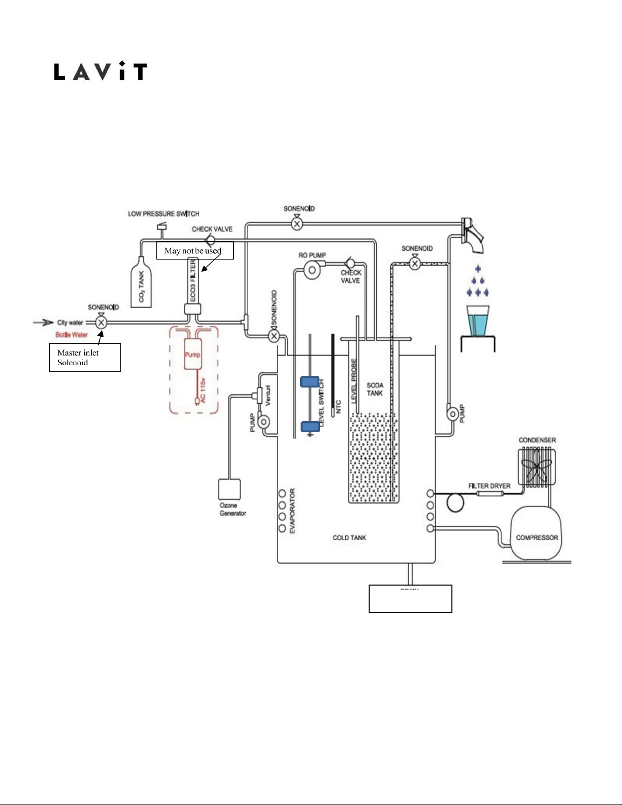
Water Flow Diagram
COLD TANK
DRIAN
3
18-11-26-REV-A
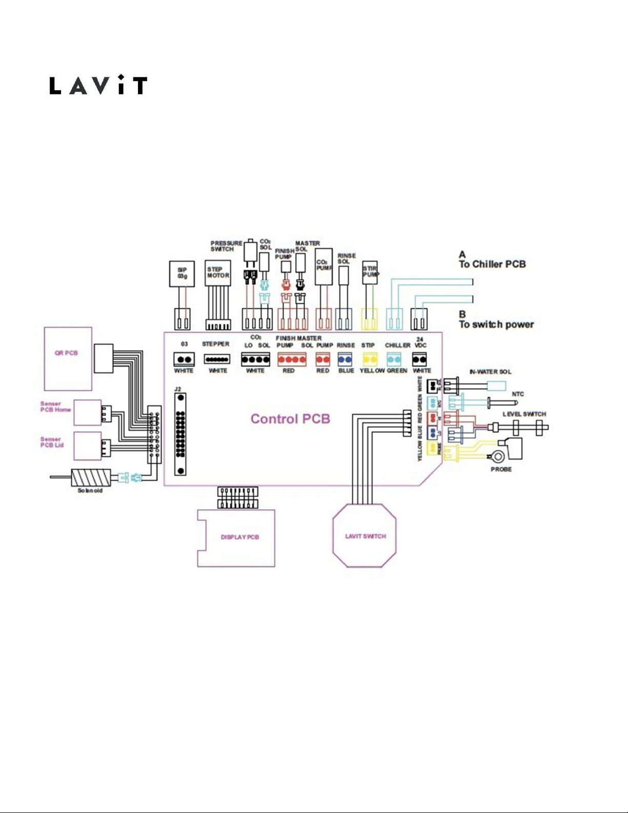
PCB Electrical Diagram
Other manuals for LB115 Series
1
Table of contents
Other Lavit Dispenser manuals


Popular Dispenser manuals by other brands

BOWMAN
BOWMAN CL003-0111 manual

SIKA
SIKA Power Cure operating instructions

Silver King
Silver King Majestic SK12MAJ Technical manual and replacement parts list

Franke
Franke F3Dn Twin Service manual

HURAKAN
HURAKAN HKN-MT1 manual

STIEBEL ELTRON
STIEBEL ELTRON UltraHot Plus Operation and installation instructions


