Entel HT840 User manual
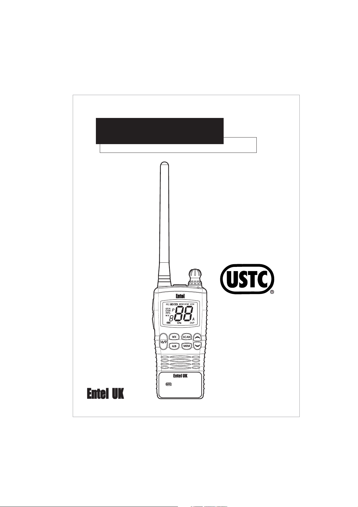
HT840
VHF submersible marine handheld transceiver
OWNERS MANUAL
Class I,ll &lll
Groups A TO G.
DIV l&ll T4
V/01
INTRINSICALLY SAFE
CLASSES I, II & III
GROUPS A TO G. DIV I & II T4
WARNING:
SUBSTITUTION OF COMPONENTS MAY
IMPAIR INTRINSIC SAFETY
USE DNLY WITH ENTEL BATTERY CNB840E
DO NOT CHARGE OR RECHARGE BATTERY
IN HAZARDOUS LOCATIONS
Submersible
Dependable
Tough

2
The HT840 transceiver displays "CE" on the serial number label,
indicating its compliance with the essential requirements of the EEC
directive for Electromagnetic Compatibility.
CE COMPLIANCE STATEMENT
This device complies with part 15 of the FCC rules. Operation is subject
to the following two conditions: (1) This device does not cause harmful
interference, and (2) this device must accept any interference received,
including interference that may undersired operation..
DECLARATION OF CONFORMITY
We, Entel UK Limited.
Of:-
4 Elstree Gate, Elstree Way,
Borehamwood, Herts.
WD6 1JD
United Kingdom.
Declare under our sole responsibility that the product:-
HT840 VHF Marine Submersible Transceiver
Serial Number......................................
to which this declaration relates is in accordance with directive 95/5/EC and
conforms to the following standards or other nominative documents :-
EN 301 178-2 V 1.1.1 (2000-08), EN60950 August 1992, A11 1997
EN 60945 1997 & ETS 300 698 Annex B December 1996(Version D only)
following the provisions of the R&TTE directive.
M. Austin
Quality Manager
5th March 2004
European Versions:-
USA Versions:-

3
1.1 INTRODUCTION
1.2 PACKING LIST
1.3 OPTIONAL ACCESSORIES
1.3.1 ATTACHING AUDIO ACCESSORIES
1.4 CONTROLS AND INDICATORS
1.5 INDICATORS
1.6 RECEPTION
1.7 TRANSMITTING
1.8 INT, USA, & CANADIAN MODES
1.9 NOAA WEATHER CHANNELS
2.0 SCAN
2.1 EMERGENCY CHANNELS
2.2 CHANNEL 9
2.3 CHANNEL A/B INSTANT ACCESS
2.3.1 PROGRAMMING A/B INSTANT ACCESS BUTTONS
2.4 OPERATION OF A/B INSTANT ACCESS BUTTONS
2.5 VOICE SCRAMBLER
2.6 VOX (voice operated transmit)
2.7 SIMPLEX/DUPEX CHANNEL USE
2.8 BATTERY CHARGING
2.8.1 OPTIONAL RAPID CHARGER
2.9 BATTERY REMOVAL/INSTALLATION
3.0 BATTERY INDICATOR
3.1 BATTERY SAFETY
3.2 TROUBLE SHOOTING
3.3 GLOSSARY OF TERMS
3.4 CHANNEL CHART
(INT, USA, CANADIAN AND private)
3.5 SPECIFICATION
(General, receive and transmit)
3.5.1 PRIVATE CHANNELS
04
04
05
06
06
09
10
11
11
12
12
13
13
13
14
14
15
15
16
16
17
17
18
18
20
21
22
25
26
TABLE OF CONTENTS

4
The Entel HT840 is a professional marine handheld transceiver
that operates on the VHF marine band. The HT840 has 58 marine
international channels, 10 weather, and 36 dealer programmable
private channels. The 58 marine channels are switchable to
comply with USA, International or Canadian regulations, this is
done via the keypad. It has an emergency channel 16 button,
which can be immediately selected from any channel by pressing
the red 16/9 key. Weather channels can also be accessed
immediately by pressing WX key.
1.1 INTRODUCTION
The supplied package: (U.S.T.C Certified, intrinsically safe)
ඖHT840
ඖCNB840E
ඖCAT40IS
ඖCBH940
ඖOwners manual
1.2 PACKING LIST
The HT840 includes the following features: Scan, A/B quick access
channels, voice scrambler, battery life indicator, vox (voice
operated transmit), low battery indicator, large LCD with back light,
Marine transceiver
1800mAh rechargeable lithium-Ion battery pack
Flexible antenna
Spring loaded belt clip

5
The HT840 is supported by a wide range of essential accessories.
For an up to date list visit our web site at www.entel.co.uk
CSA640E
CSB640E
CST640E
CCA230
CCA12
CNB840E
CMP840
EA19/840
EA15/840
EA12/840
CHP1/840
EPT40/840
CHP800/HD
CHP800/HS
CHP800D
CXR5/840
CXR16/840
EHP840
CLC940
CAT40IS
CBH940
Single pod intelligent rapid charger, 110/230v operation
Six pod intelligent rapid charger, 110/230v operation
3 or 6 pod battery conditioner/analyser
230v drop in trickle charger. (Also available as 110v -CCA110)
12v drop in trickle charger
7.4V 1800mAh rechargeable lithium-Ion battery pack, with rear clip
Submersible, noise cancelling speaker microphone (heavy duty)
Earpiece microphone with PTT button
Covert style ear/microphone with transparent acoustic tube
D Shape earpiece microphone with in-line PTT
Single earpiece headset with in-line PTT(vox)
Bone conductive earpiece microphone
Heavy duty double ear defender for hardhat with PTT (vox)
Heavy duty single ear defender for hardhat and PTT (vox)
Heavy duty double ear defender with headband and PTT (vox)
Skull microphone (vox)
Throat microphone (vox)
Covert style earpiece
Heavy duty leather case with belt loop & carry strap
Flexible antenna
Spring loaded rear clip
1.3 OPTIONAL ACCESSORIES (U.S.T.C Certified)
Accessories suitable for vox operation have been marked (vox)
NOTE: DO NOT CHARGE OR REMOVE THE BATTERY PACK IN
THE HAZARDOUS AREA LOCATION.
NOTE: THE USE OF NON ENTEL APPROVED ACCESSORIES WILL
INVALIDATE YOUR U.S.T.C INTRINSICALLY SAFE APPROVAL

6
Locate accessory connector cover marked "ACC" Lift cover and
rotate (screw) the connector as shown in the diagram below.
1.3.1 ATTACHING AUDIO ACCESSORIES
ྙPOWER SWITCH/VOLUME CONTROL
Powers the transceiver on and off, and adjusts volume level.
ྚSQUELCH CONTROL
To set the squelch, rotate the control fully anti-clock wise,
then rotate the control clockwise until the white noise stops.
If you occasionally get breakthrough of unwanted noise,
rotate the control a little further clockwise.
ྛPUSH TO TALK SWITCH
Hold down to transmit, release to receive.
1.4 CONTROLS AND INDICATORS
Figure 1. Attaching the accessory connector
Note: The accessory socket is waterproof
without the ACC cover in place. However, when
not using an audio accessory we strongly
advise keeping the ACC cover firmly pressed in
its recess to prevent foreign objects from getting
into the socket.
7
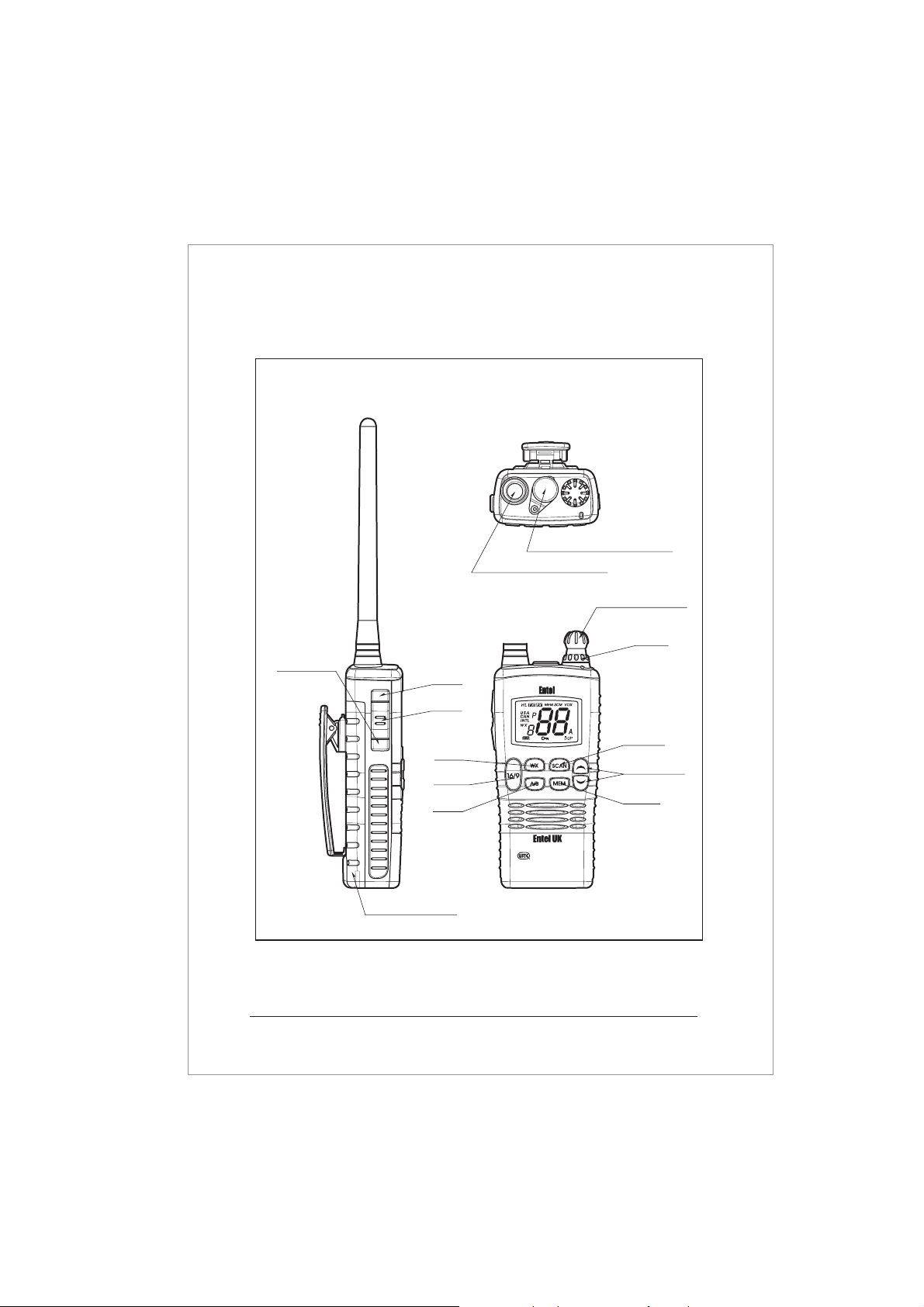
Figure 2. Controls and Connectors
ྙPOWER SWITCH
ྚSQL
ྛPTT
ྜUP/DOWN
ྜྷ16/9
ྞWX
ྟSCAN
ྠMEM
ྡA/B
ྡྷH/L
ྣLAMP/KEY
LOCK
ྤANTENNA CONNECTOR
ྥBATTERY PACK
ྦACCESSORY CONNECTOR
INTRINSICALLY SAFE
CLASSES I, II & III
GROUPS A TO G. DIV I & II T4
WARNING:
SUBSTITUTION OF COMPONENTS MAY
IMPAIR INTRINSIC SAFETY
USE DNLY WITH ENTEL BATTERY CNB840E
DO NOT CHARGE OR RECHARGE BATTERY
IN HAZARDOUS LOCATIONS

_
ྜUP/DOWN buttons
Select the desired channel by pressing the UP/DOWN buttons.
For fast channel selection hold down for more than 1 second.
ྜྷ16/9 button
A momentary press of this button recalls channel 16 from any
location. Holding this button for 1 second recalls channel 9.
ྞWX button
Immediately recalls the weather channels.
ྟSCAN button
Starts scanning programmed channels.
ྠMEM button
Memorises a desired channel for scanning.
ྡA/B button
Immediately recalls up to 2 user-defined channels.
ྡྷH/L button
Press this button for one second to toggle between high and
low power. (1 & 5 watts)
ྣLAMP/KEY LOCK
Momentarily pressing this button illuminates the LCD display.
Holding this button for over 1 second activates the key lock.
To deactivate press button again.
ྤANTENNA CONNECTOR
Connects the supplied flexible antenna or an optional external
aerial adaptor.
ྥBATTERY PACK
Rechargeable lithium-Ion battery pack provides DC power
source to the transceiver.
ྦACCESSORY CONNECTOR
To connect any HT840 approved audio accessory.
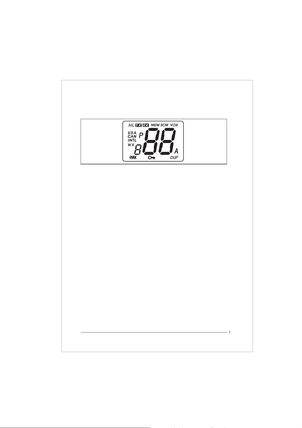
CHANNEL DISPLAY
The operating channel.
H/L
H indicates high power (5 watts) L indicates low power (1 watt)
USA/CAN/INTL
Indicates the channel set for; USA, Canadian, and International
waters.
A Indicator
A ship-to-ship channel in U.S.A or Canadian mode whose
counterpart in the International mode is a public correspondence
(marine operator) channel.
WX
NOAA weather channel (U.S,A & Canadian waters only)
TX Indicator
Indicates transmission in progress
VOX
Voice operated mode enabled
SCAN
SCAN mode in progress
MEM
Indicated channel is memorised for scanning
1.5 INDICATORS
Figure 3. LCD indications

10
SCM
Scrambler mode enabled (versions A & B only)
LAMP /
The keypad is locked, with the exception of the [PTT], [H/L] and
[LAMP] buttons.
BATTERY LIFE INDICATOR
The lithium-Ion battery of your transceiver is continually monitored
for your convenience and safety.
1. Turn the transceiver on by rotating the volume control in a
clockwise direction. A power on tone is generated after 1
second to indicate the transceiver has passed its
self-diagnostic test. During standby the LED indicator will
pulse amber every 3 seconds, to further verify its circuitry is
functioning correctly. Select the desired audio level by further
rotating the control clockwise. After power on, the transceiver
will always default to the last channel selected.
2. Turn the squelch control fully counter clockwise, then rotate
clockwise until the white noise stops. This condition is known as
the "squelch threshold" If the control is turned clockwise past
this point, weak signals may not be received.
No noise or signal is heard until a signal is received that
exceeds the squelch threshold.
3. Select the desired channel using the [UP/DOWN] buttons.
A full listing of channels can be found on page 22.
Sometimes, a slight adjustment of the squelch threshold is needed
as some channels have a higher noise level than others.
4. When receiving a signal the LED indicator illuminates green.
A "RX" indication is also displayed on the LCD.
1.6 RECEPTION

11
1.7 TRANSMITTING
1. Perform steps 1 through 3 of RECEPTION.
2. Before transmitting, monitor the channel and make sure it is
clear.
3. For communications over short distances, press the [H/L] key
and select low power (1 watt) Transmitting on 1 watt prolongs
battery life, and should be selected whenever possible.
4. When receiving a signal, wait until the signal stops before
transmitting. The transceiver cannot transmit and receive
simultaneously.
5. Press the [PTT] (push-to-talk) switch to begin your transmission.
To confirm transmission in progress the LCD indicator illuminates
TX and the LED illuminates RED.
6. Holding the transceiver 1 inch from your mouth speak slowly
and clearly into the microphone.
7. When the transmission is finished, release the [PTT] switch.
1.8 INT, USA, & CANADIAN MODES
In compliance with worldwide license regulations
the following version of HT840 are available:
Version A : INT, USA, & Canadian modes
Version B, C and D : INT mode only
1. In the case of version A only ; to change the channel set of the
transceiver, hold down the [WX] key, The mode changes from
U.S.A to Canadian to International.
2. Refer to the marine channel charts in this booklet for allocated
channels in each mode.

12
1.9 NOAA WEATHER CHANNELS
(Applicable to version A model only)
1. To receive a weather channel, press the [WX] key.
The transceiver enters into weather channel mode.
2. There are 10 weather channels. Use the UP or DOWN buttons
to select the desired weather channel.
3. To exit from the weather channels, press the [WX] key.
The transceiver recalls the previous working channel.
2.0 SCAN
1. Select the desired channel to be scanned using
the & buttons.
2. Press the [MEM] button to store the channel into the transceivers
memory. [MEM] is displayed on the LCD.
This channel is now memorised to be scanned.
3. To scan further channels, repeat steps 1 & 2.
4. To delete a channel from the transceivers scan memory,
simply press [MEM] button again whilst the memorised channel
is displayed. [MEM] disappears.
5. All channels programmed remain in the transceivers scan
memory, even if the power is switched off.
6. Adjust the squelch control until the white noise is eliminated.
7. To start scanning, press the [SCAN] key. The scan proceeds from
the lowest to the highest programmed channel number and
stops on channels when a transmission is received.
8. To stop the scan at any time, press the [SCAN] key.

2.1 EMERGENCY CHANNELS
To select the emergency channel, press the [16/9] button from
any channel. Channel 16 appears on the display. To recall the
previous channel used, press the [16/9] button once again.
2.3 CHANNEL A/B INSTANT ACCESS
For your convenience, two user assigned channels can be
programmed for instant access. If the [A/B] key is pressed and no
channel A or B has been assigned, a short beep will be heard.
2.2 CHANNEL 9
Channel 9 is used as a hailing channel for initial, non-emergency
contact with other vessels. Hold down the [16/9] key for 1
second to select channel 9.

14
2.4 OPERATION OF A/B INSTANT ACCESS BUTTONS
Pressing the [A/B] button will toggle between A, B and the previous
selected working channel. Channel A is represented by the "A"
to the left of the channel number on the LCD, and channel B
is represented by "b". NOTE: Do not confuse this "A" with the one
that is sometimes displayed to the right hand side of the channel
number (in U.S.A and Canadian modes)
2.3.1 PROGRAMMING A/B INSTANT ACCESS BUTTONS
1. Hold down the [A/B] key and turn on the transceiver.
2. The letter A will appear on the display, and dashes "_ _"
indicate that no channel has been designated channel A.
3. Press the [UP/DOWN] key until the desired channel number is
displayed.
4. With the desired channel number displayed, press the [MEM]
key once. The "A" will stop flashing, indicating that the displayed
channel is now designated channel A.
5. Press the A/B button again. The letter "b" will appear on the
display. Repeat steps 2 through to 4.
6. Switch transceiver off and on to exit this mode and save
changes.
NOTE: Should you later wish to delete any stored channels simply
press "MEM" key whilst in A/B programming mode.

15
( HT840 versions A & B only )
Press the [SCAN] key and switch the transceiver on simultaneously.
"SCM" will be displayed on the LCD confirming that the voice
scrambler of your HT840 is now activated.
To exit scramble mode simply switch the radio off and on.
**Legislation for the use of a scrambler (encryption) varies from
country to country. We recommend that you check with your
dealer prior to using this feature.
In VOX mode the transceiver will react to your voice, and transmit
automatically without you having to press the PTT button.
There is always a slight delay for the electronic switching, and
consideration will need to be given. To get optimum performance
from the VOX feature you should use a noise cancelling headset
or earpiece microphone (see accessory options)
2.5 VOICE SCRAMBLER
Press the [MEM] button and switch the transceiver on.
VOX will be displayed on the LCD, along with "oFF" which indicates
VOX is switched off, 1 is for low sensitivity, 5 is for normal sensitivity,
and 9 is for high sensitivity. Use the [UP/DOWN] button to select the
desired level,press MEM to confirm, the transceiver is now set to VOX.
To switch VOX off, go back into VOX programming mode by holding
the "MEM" button whilst switching on. Press the UP/DOWN button
until the vox level is "OFF".
2.6 VOX(voice operated transmit)
NOTE: The scrambler cannot be enabled on channel 16 & 9.

16
If you have a license to use a specific simplex or semi-duplex
channel, contact your dealer who may be able to program your
channel using the transceivers private channel memory.
2.7 SIMPLEX/DUPLEX CHANNEL USE
Your transceiver has been factory programmed in accordance
with FCC (USA), industry Canada and International regulations.
The mode of operation cannot be altered from simplex to duplex
or vice versa. Simplex or duplex mode is automatically activated,
depending on the channel and the channel set and whether USA,
Canadian, or International mode is selected.
Refer to the channel charts listed later in this user manual.
2.8 OPTIONAL TRICKLE CHARGER -model CCA230
1. Connect the CWC640 AC adaptor to the charger pod.
The LED status light will illuminate green indicating ready for
charge.
2. Turn the transceiver off.
3. Insert the battery pack into the pod, either with or
without the transceiver attached. The LED status light changes
from green to RED and trickle charge begins.
4. A fully discharged battery pack will take approximately 6 hours
to charge, depending on the remaining power condition. When
charge is complete, the LED status light turns green.
NOTE: The CWC640 AC adaptor can be replaced by the CMC640
12v charger cable. Charge time remains at 6 hours.

17
2.8.1 OPTIONAL RAPID CHARGER-model CSA640E
1. Connect the CSA640E to a
mains supply(110 to 230V).
When switching on the LED
flashes orange briefly to
confirm self-diagnostic
test complete.
2. Turn the transceiver off.
3. Insert the battery pack into
the CSA640E charger, either with or without the transceiver
attached. The LED will illuminate red to indicate rapid charge
in progress.
4. Charge time for a fully discharged battery pack will take up to
120 minutes. On completion the LED turns green.
2.9 BATTERY REMOVAL/INSTALLATION
1. Turn the transceiver off.
2. Using a coin, rotate the battery screw anti-clockwise 2 or 3 turns.
**Ensure that you do not hold the battery pack when
unscrewing the release screw!
Figure 4. OPTIONAL CCA230 trickle charger
DC12V
Figure 4-1.
OPTIONAL CSA640E
rapid charger
110-230VAC
18
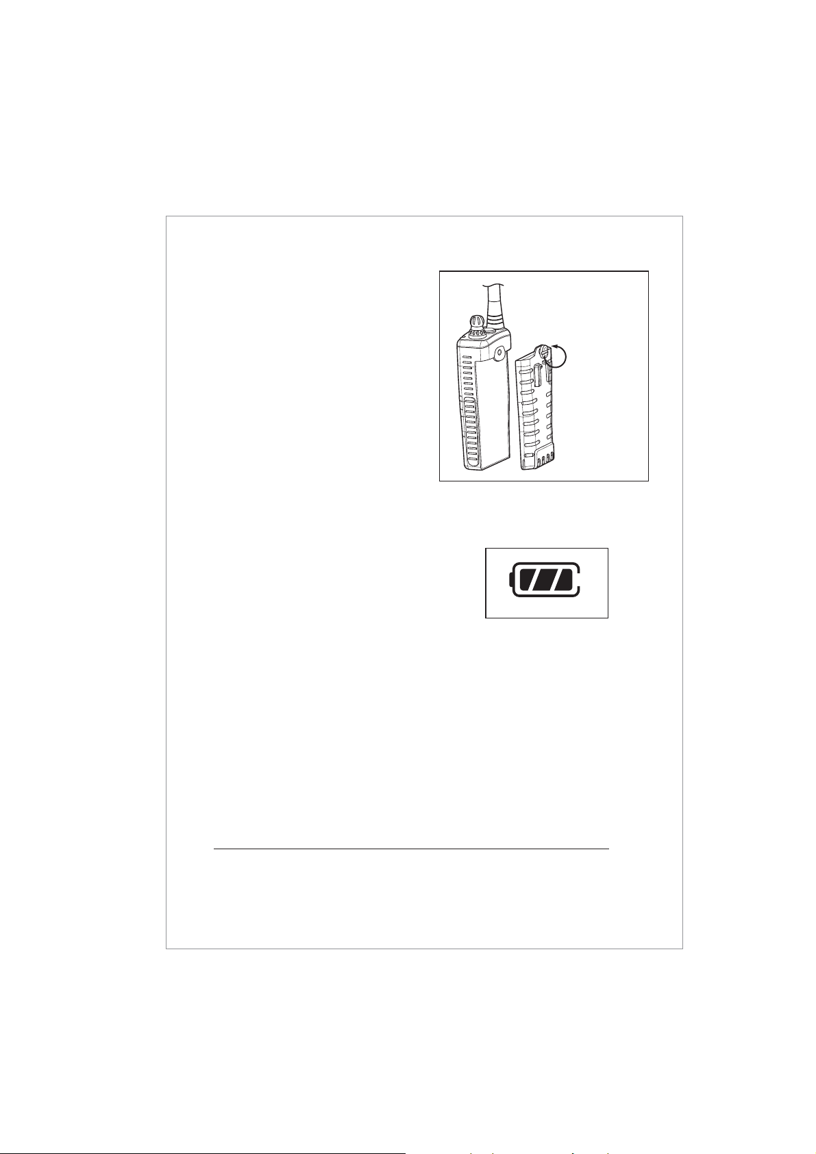
3.0 BATTERY INDICATOR
For your safety and convenience your
transceiver continually monitors the
battery pack and gives an indication
on the LCD:
3 Segments : 12hours
2 Segments : 1hour
1 Segment : 20mins
3.1 BATTERY SAFETY
The battery pack of your transceiver contains lithium-Ion cells.
This type of battery stores a charge powerful enough to be
dangerous if misused or abused, especially when removed from
the transceiver. Please observe the following precautions
detailed on page 19.
Figure 6. Battery Indicator
Figure 5. Battery removal / attachment
To remove rotate the screw
anti-clockwise
3.To attach battery, locate the
bottom section of the battery and
press the battery against the
transceiver, and rotate the battery
screw clockwise.
NOTE: The HT840 must only be
used with the CNB840E battery
pack manufactured by Entel UK.
Failure to comply will invalidate
your USTC Certification.

19
Lithium-Ion battery packs must be recycled or disposed of
properly. For requirements in your area, check with the dealer
from whom you purchased your transceiver.
DO NOT OVERCHARGE
When using the CWC640 do not charge the transceiver for more
than 8 hours. Heat generated by overcharging can shorten battery
life and cause other battery pack component failures
DO NOT INCINERATE
Do not dispose of your CNB840E battery in a fire or incinerator.
The heat of fire may cause battery cells to explode and/or
release dangerous gases.
DO NOT SHORT BATTERY PACK TERMINALS
Shorting the terminals that power the transceiver can cause sparks,
severe over heating, burns, and battery cell damage.
If the short is of sufficient duration, it is possible to melt the battery
components. Do not place a loose battery pack on or near a
metal surface or objects such as paper clips, keys, tools etc.
When the battery pack is installed on the transceiver, the terminals
that transfer current to the transceiver are not exposed.
The terminals that are exposed on the battery pack when it is
mounted on the transceiver are charging terminals only and do
not constitute a hazard.
DISPOSE OF BATTERY PACKS PROPERLY

20
TROUBLESHOOTING CHART
SYMPTOM
Transceiver not
switching on
Battery needs charging
Battery is exhausted
Charge the battery pack
Replace the battery pack
The scan key does not
start the scan
No channels
memorised (MEM)
Squelch is not adjusted
Use the MEM key to enter
desired channels into scan
memory
Adjust the squelch to
threshold or to the point
where the white noise just
disappears.
REMEDYPROBABLE CAUSE
3.2 TROUBLE SHOOTING
Cannot change any
function
Key lock is switched on Turn key lock off
LED on CCA230 & CWC640
does not illuminate when
charging
Defective battery,
CCA230, or CWC640
Dirty terminal contact
on CCA230
Contact your dealer
Clean contacts with dry
clean cloth
No transmit or Hi power
can be selected
Some channels are low
power only
Battery pack exhausted
Change to high power
channel
Recharge the battery pack
Transceiver transmits
without pressing PTT button
Buttons seem to work
intermittently
VOX has been enabled Hold MEM button for 2 secs,
use UP or DOWN button
and select 0 to turn
VOX off.
Table of contents
Other Entel Transceiver manuals


Entel
Entel HT644 GMDSS User manual

Entel
Entel HX400 series User manual

Entel
Entel HX402 HX422 User manual

Entel
Entel HT9506 User manual

Entel
Entel HT544 Setup guide

Entel
Entel HT952 User manual

Entel
Entel HT700 Series User manual

Entel
Entel HT700 2.0 Series User manual

Entel
Entel HT702 User manual

Entel
Entel HT920 User manual


