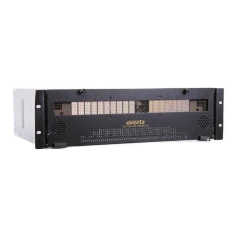
evertz 7700 Series User manual

7700 MultiFrame Manual
7707MB Multi-Signal SDTV Fiber Transciever
Revision 1.5
TABLE OF CONTENTS
1. OVERVIEW.......................................................................................................................................... 1
2. INSTALLATION................................................................................................................................... 4
2.1. AES AUDIO AND AUXILLIARY I/O............................................................................................ 5
2.1.1. Connecting the AES Inputs ............................................................................................. 5
2.1.2. Connecting the RS232/422 Serial Data Port................................................................... 6
2.2. CONNECTING THE GPI INPUTS AND GPO OUTPUTS............................................................ 6
2.3. INSTALLING THE BULKHEAD BREAKOUT PANEL ............................................................... 7
2.3.1. Connecting the Breakout Panel AES Inputs.................................................................... 8
2.3.2. Connecting the Breakout Panel RS232/422 Serial Data Port ......................................... 8
2.4. CARE AND HANDLING OF OPTICAL FIBER............................................................................ 9
2.4.1. Safety .............................................................................................................................. 9
2.4.2. Assembly......................................................................................................................... 9
2.4.3. Labeling........................................................................................................................... 9
2.4.4. Handling and Connecting Fibers ................................................................................... 10
3. SPECIFICATIONS............................................................................................................................. 11
3.1. SERIAL VIDEO INPUT ............................................................................................................. 11
3.2. SERIAL VIDEO OUTPUT ......................................................................................................... 11
3.3. AES AUDIO INPUTS ................................................................................................................ 11
3.4. AES AUDIO OUTPUTS................................................................................................................. 11
3.5. OPTICAL INPUT/OUTPUT....................................................................................................... 12
3.6. SERIAL DATA PORT ............................................................................................................... 12
3.7. GENERAL PURPOSE INPUTS................................................................................................ 12
3.8. GENERAL PURPOSE OUTPUTS............................................................................................ 12
3.9. SYSTEM PERFORMANCE ...................................................................................................... 13
3.10.ELECTRICAL ........................................................................................................................... 13
3.11.PHYSICAL................................................................................................................................ 13
3.12.COMPLIANCE.............................................................................................................................. 13
4. STATUS INDICATORS AND DISPLAYS ......................................................................................... 14
4.1. STATUS INDICATOR LEDS..................................................................................................... 14
4.2. DOT-MATRIX DISPLAY........................................................................................................... 14
4.2.1. Displaying the Video Standard ...................................................................................... 15
4.2.2. Displaying the Audio Presence ..................................................................................... 15
4.2.3. Displaying the Serial Data Activity................................................................................. 16
4.2.4. Selecting LED Display................................................................................................... 16
4.2.5. Displaying optical power ............................................................................................... 16
7700 MultiFrame Manual
7707MB Multi-Signal SDTV Fiber Transciever
Revision 1.5
4.2.6. Displaying the State of the General Purpose Outputs................................................... 16
4.2.7. Displaying the State of the General Purpose Inputs ..................................................... 16
4.2.8. Displaying the Firmware Version................................................................................... 17
5. CARD EDGE MENU SYSTEM.......................................................................................................... 18
5.1. NAVIGATING THE MENU SYSTEM......................................................................................... 18
5.2. TOP LEVEL MENU STRUCTURE............................................................................................ 18
5.2.1. Setting EDH Detection .................................................................................................. 19
5.2.2. Setting the Orientation of the Text on the Card Edge Display....................................... 19
5.2.3. Setting the Default Output Video Standard ................................................................... 19
6. CARD EDGE CONTROLS ................................................................................................................ 20
7. JUMPERS.......................................................................................................................................... 21
7.1. SELECTING WHETHER LOCAL FAULTS WILL BE MONITORED
BY THE GLOBAL FRAME STATUS........................................................................................ 22
7.2. SELECTING WHETHER MODULE WILL BE CONTROLLED FROM THE
LOCAL CONTROLS OR THROUGH THE VISTALINK
®
INTERFACE...................................... 22
7.3. SELECTING THE DATA COMMUNICATIONS STANDARD (RS-232 OR RS-422)................. 22
7.3.1. Configuring RS422 Device Communication between a Controller and Tributary.......... 23
7.4. SELECTING THE DEFAULT BEHAVIOUR OF THE INPUTS WHEN THERE IS NO SIGNAL
CONNECTED........................................................................................................................... 23
7.5. CONFIGURING THE MODULE FOR FIRMWARE UPGRADES.............................................. 24
7.6. SELECTING THE AES INPUT CONFIGURATION (BALANCED OR UNBALANCED)........... 24
7.7. SETTING THE BALANCED AES INPUT LEVEL SENSITIVITY............................................... 24
7.8. SELECTING THE AES OUTPUT IMPEDANCE ....................................................................... 24
7.9. SETTING THE AES OUTPUT LEVEL ...................................................................................... 25
7.10.SELECTING THE GPI PULLUP VOLTAGE ............................................................................. 25
7.11.SELECTING NORMALLY OPEN OR CLOSED GPOS ............................................................ 26
8. VISTALINK
®
REMOTE MONITORING/CONTROL........................................................................... 27
8.1. WHAT IS VISTALINK
®
?............................................................................................................... 27
8.2. VISTALINK
®
MONITORED PARAMETERS .............................................................................. 28
8.3. VISTALINK
®
CONTROLLED PARAMETERS ........................................................................... 29

7700 MultiFrame Manual
7707MB Multi-Signal SDTV Fiber Transciever
Revision 1.5
Figures
Figure 1-1: 7707MB Block Diagram ......................................................................................................................2
Figure 2-1: 7707MB & 7707MB-F2 Rear Panels ..................................................................................................4
Figure 2-2: Breakout Panel for Wiring Connections..............................................................................................7
Figure 2-3: Reproduction of Laser Certification and Identification Label ..............................................................9
Figure 7-1: Location of Jumpers – I/O Module....................................................................................................21
Figure 7-2: Location of Jumpers – Main Module.................................................................................................21
Figure 7-3: Receiver Input Pull-up Configuration ................................................................................................23
Figure 7-4: GPI Input Circuitry.............................................................................................................................25
Figure 7-5: Selecting Normally Open or Closed GPO Configuration ..................................................................26
Tables
Table 1-1: Typical Application Configurations.......................................................................................................3
Table 2-1: AES / SERIAL I/O Connector Pin Definitions.......................................................................................5
Table 2-2: Breakout Panel RS232/422 Connector Pin Definitions........................................................................8
Table 7-1: I/O Jumper Settings ...........................................................................................................................26
Table 8-1: VistaLINK
®
Monitored Parameters.....................................................................................................28
Table 8-2: VistaLINK
®
Controlled Parameters ....................................................................................................29

7700 MultiFrame Manual
7707MB Multi-Signal SDTV Fiber Transciever
Revision 1.5
This page left intentionally blank

7700 MultiFrame Manual
7707MB Multi-Signal SDTV Fiber Transciever
Revision 1.5
REVISION HISTORY
REVISION DESCRIPTION DATE
1.0 First Release Oct 02
1.1 Added 8 new CWDM wavelengths Dec 02
1.2 Corrected Jumper designations on Figure 4 Jan 03
1.3 Added Application Configuration table Aug 03
1.4 Updated safety section and added assembly and labeling sections Aug 05
1.5 Added in –F2 rear plate, updated features, specs & VistaLINK
®
description.
Fixed format. Nov 08
Information contained in this manual is believed to be accurate and reliable. However, Evertz assumes no responsibility for the use thereof nor for
the rights of third parties, which may be affected in any way by the use thereof. Any representations in this document concerning performance of
Evertz products are for informational use only and are not warranties of future performance, either expressed or implied. The only warranty offered
by Evertz in relation to this product is the Evertz standard limited warranty, stated in the sales contract or order confirmation form.
Although every attempt has been made to accurately describe the features, installation and operation of this product in this manual, no warranty is
granted nor liability assumed in relation to any errors or omissions unless specifically undertaken in the Evertz sales contract or order confirmation.
Information contained in this manual is periodically updated and changes will be incorporated into subsequent editions. If you encounter an error,
please notify Evertz Customer Service department. Evertz reserves the right, without notice or liability, to make changes in equipment design or
specifications.

7700 MultiFrame Manual
7707MB Multi-Signal SDTV Fiber Transciever
Revision 1.5
WARNING
Never look directly into an optical fiber. Non-reversible damage to the eye can
occur in a matter of milliseconds.
"
Do not hook up the 7707MB DWDM cards directly with a short fiber optic
cable. The 7707MB DWDM cards produce +7dBm of power which will
damage the receiver if connected directly.

7700 MultiFrame Manual
7707MB Multi-Signal SDTV Fiber Transciever
Revision 1.5
7707MB
-1
1. OVERVIEW
The 7707MB Multi-Signal Fiber Transceiver is a VistaLINK
®
enabled fiber transmitter/receiver for SDI
Video, AES Audio, RS422 control and GPIO. This single card module transports and receives one bi-
directional SDI Video plus two bi-directional AES Audio plus one bi-directional RS422 plus two bi-
directional GPI’s and GPO’s. These signals are combined using Time Domain Multiplex (TDM) technology
and transmitted over a single fiber. A pair of 7707MB Multi-Signal Fiber Transceivers permits bi-directional
communication between cards.
The 7707MB will transparently pass both incoming and outgoing SDI video feeds with embedded AES
audio and/or any other data in the horizontal or vertical ancillary data space. Minimal Audio to Video
latency over the transport interface is also achieved.
The fiber output is available in an assortment of optical wavelengths, accommodating standard, or CWDM
transmission schemes.
The 7707MB occupies one card slot and can be housed in either a 1RU frame, which will hold up to three
modules, or a 3 RU frame, which will hold up to 15 modules.
Features:
•Bi-directional fiber optic transceiver for 1 SDI Video, 2 AES Audio, 1 RS-232/422 and 2 GPI/O
•Supports 525 or 625 line 4:2:2 component SDI signals
•Supports 32, 44.1, 48kHz AES audio
•Dolby-E™ compatible
•Supports bi-directional RS-422 rates up to 3Mb/s
•Low Audio to Video latency
•Signal transport over fiber uninterrupted by loss of input SDI, AES or Serial Data feeds
•Built-in jitter attenuation
•VistaLINK
®
capability is available when modules are used with the 3RU 7700FR-C or 350FR portable
frame and a 7700FC VistaLINK
®
Frame Controller module in slot 1 of the frame
•Comprehensive signal and card status monitoring via four digit card edge display or remotely through
SNMP and VistaLINK
®
•Local display of optical signal strength, video, audio, data presence, video and AES formats and EDH
errors
•Fully hot-swappable from front of frame with no fiber disconnect/reconnect required
•Bi-directional optical input/output
•Accepts any wavelength in the 1270nm to 1610nm range
•Optical output wavelengths of 1310nm, 1550nm and up to sixteen CWDM wavelengths (ITU-T
G.694.2 compliant)
•DWDM wavelengths (ITU-T G.694.1 compliant) also available
•
Supports single-mode and multi-mode fiber optic cable

7700 MultiFrame Manual
7707MB Multi-Signal SDTV Fiber Transciever
7707MB
-2 Revision 1.5
SDI VIDEO
INPUT RECLOCKER
AES AUDIO
INPUTS
INPUT
RECEIVER
OUTPUT
DRIVER
AES AUDIO
OUTPUTS
AES 1
AES 2
GPI 1
AES 1
AES 2
SDI VIDEO
OUTPUT CABLE DRIVER
TDM
DEMUX
TDM
MUX
TX/RX
INTERFACE
OPTICAL
TRANSMITTER
OPTICAL
RECEIVER
OPTICAL
SPLITTER/
COMBINER
FIBER
INPUT/
OUTPUT
CONTROL/
INDICATIONLOCAL
CONTROL
®
LOCAL
INDICATION
RS422/232
GPI 2
GPI 1
RS422/232
GPI 2
FIBER
INPUT
FIBER
OUTPUT
Figure 1-1: 7707MB Block Diagram

7700 MultiFrame Manual
7707MB Multi-Signal SDTV Fiber Transciever
Revision 1.5
7707MB
-3
The following chart shows some typical applications and power budget calculations:
Transmit Side Receive Side
Fiber
Type Fiber
Links Optical/Link
Budget Ordering
Product Info TX
Power Ordering
Product Info RX
Sensitivity Description
Multi-Mode 2 < 3km 7707MB13-F2 -7dBm 7707MB13-F2 -28dBm
1310nm on Tx & Rx
fibers
Single-
Mode 2 21dB/50km 7707MB13-F2 -7dBm 7707MB13-F2 -28dBm
1310nm on Tx & Rx
fibers
Single-
Mode 1 14dB/30km* 7707MB13 -10dBm 7707MB13 -24dBm
1310nm, bi-
directional, one fiber
Single-
Mode 1(WDM) 25dB/60km 7707MB13M-W -1dBm 7707MB15-W -26dBm
1310nm/1550nm,
WDM, bi-directional
on one fiber
Single-
Mode 1(CWDM) 24dB/80km** 7707MBxx-F2 0dBm 7707MByy-F2 -28dBm
Different CWDM
wavlenghts on Tx &
Rx, with 8 channel
CWDM Mux/Demux**
Single-
Mode 1(DWDM) 31dB/105km** 7707MBxxxx-F2 7dBm 7707MByyyy-F2 -28dBm
Different DWDM
wavlenghts on Tx &
Rx, with 8 channel
DWDM Mux/Demux**
*With >20dB return loss on fiber Interface Tx Power/Rx Sensitivity are nominal values ±1dBm
**Assume 8 Ch Mux/Demux loss of 3.5dB Fiber Loss = 0.4/0.3dB per km @ 1310nm/1550nm
Table 1-1: Typical Application Configurations

7700 MultiFrame Manual
7707MB Multi-Signal SDTV Fiber Transciever
7707MB
-4 Revision 1.5
2. INSTALLATION
The 7707MB comes with a companion rear plate that has two BNC connectors, one female DB15 and one
SC/PC, SC/PC with cover (shown), ST/PC or FC/PC optical connector. For information on mounting the
rear plate and inserting the module into the frame see the 7700FR chapter section 3.
Figure 2-1: 7707MB & 7707MB-F2 Rear Panels
SDI IN: Input BNC connector for 10-bit serial digital video signals compatible with the
SMPTE 259M, or SMPTE 305M standards. Optional support for DVB-ASI signals.
This input provides adaptive equalization compensation for up to 300m of industry
standard Belden 1694 cable, at 270Mb/s.
SDI OUT: Output BNC connector for reclocked serial digital component video signal,
compatible with the SMPTE 259M, or SMPTE 305M standards.
OPTICAL I/O: SC/PC, SC/PC with cover (shown), ST/PC or FC/PC female connector. This optical
output contains the bi-directional SDI video signal, the bi-directional AES audio
present at the AES1 and AES2 inputs/outputs and the bi-directional Serial Data and
GPI/O signals. Any ancillary data (i.e. embedded audio, closed captioning, etc)
present in the input SDI video stream prior to multiplexing is transparently passed
through to the output. This connector also serves as the optical input for the bi-
directional SDI video, AES, serial data and GPI/O signals.

7700 MultiFrame Manual
7707MB Multi-Signal SDTV Fiber Transciever
Revision 1.5
7707MB
-5
2.1. AES AUDIO AND AUXILLIARY I/O
A 15-pin High Density D connector labeled AES / SERIAL I/O contains 2 AES Audio inputs, 2 AES Audio
outputs and a bi-directional Serial Data port.
Pin
# Name Description
1 AES2OUT(+) Balanced AES2 + or Unbalanced AES 2 Output
2 AES1OUT(-) Balanced AES1 – Output
3 GND Signal Ground
4 AES1IN(-) Balanced AES1 – Input
5 AES1IN(+) Balanced AES1 + or Unbalanced AES 1 Input
6 AES1OUT(+) Balanced AES1 + or Unbalanced AES 1 Output
7 AES2OUT(-) Balanced AES2 – Output
8 GND Signal Ground
9 SOUT1(-) RS232 Port 1 Transmit out or RS422 Transmit - out
10 SOUT2(+) RS232 Port 2 Transmit out or RS422 Transmit + out
11 GND Signal Ground
12 SIN1(-) RS232 Port 1 Receive In or RS422 Receive – in
13 SIN2(+) RS232 Port 2 Receive In or RS422 Receive + in
14 AES2IN(-) Balanced AES2 – Input
15 AES2IN(+) Balanced AES2 + or Unbalanced AES 2 Input
Table 2-1: AES / SERIAL I/O Connector Pin Definitions
2.1.1. Connecting the AES Inputs
AES INPUT: 4 Pins on the DB15 connector are used to carry balanced or unbalanced AES audio
inputs for channels 4&5 (AES 1) and 14&15 (AES 2) of an audio group. Each input
occupies two pins (+, -) on the DB15 with a shared GND pin. AES inputs can be
synchronous or asynchronous to each other and/or input SDI video.
For Balanced AES signals connect the + and – signals to the respective input pins. The
AES Term Jumpers J26 and J27 must be set to the 110 positions for proper termination
of the balanced AES inputs. The AES LEVEL jumpers J24 and J25 are normally set to
the HI position for balanced AES signal levels of 2 to 7 volts. For signal levels below 2
volts, move the AES LEVEL jumpers to the LO position.
Unbalanced AES signals should be connected to the AES+ input pin with the ground
connected to the AES- input pin. The AES Term Jumpers J26 and J27 must be set to
the 75 positions for proper termination of the unbalanced AES inputs. The AES LEVEL
jumpers J24 and J25 should be in the LO position when the TERM jumpers are in the
75 position.

7700 MultiFrame Manual
7707MB Multi-Signal SDTV Fiber Transciever
7707MB
-6 Revision 1.5
AES OUTPUT: 4 Pins on the DB15 connector are used to carry balanced or unbalanced AES audio
outputs for channels 6&2 (AES 1) and 1&7 (AES 2) of an audio group. Each output
occupies two pins (+, -) on the DB15 with a shared GND pin. AES inputs can be
synchronous or asynchronous to each other and/or input SDI video.
For Balanced AES signals connect the + and – signals to the respective output pins.
The AES Term Jumpers J26 and J27 must be set to the 110 positions for proper
termination of the balanced AES inputs. The AES LEVEL jumpers J24 and J25 are
normally set to the HI position for balanced AES signal levels of 2 to 7 volts. For signal
levels below 2 volts, move the AES LEVEL jumpers to the LO position.
Unbalanced AES signals should be connected to the AES+ output pin with the ground
connected to the AES- input pin. The AES Term Jumpers J26 and J27 must be set to
the 75 positions for proper termination of the unbalanced AES inputs. The AES LEVEL
jumpers J24 and J25 should be in the LO position when the TERM jumpers are in the
75 position.
2.1.2. Connecting the RS232/422 Serial Data Port
RS232/422: 4 Pins on DB15 connector are used for a bi-directional serial data port conforming to
RS422 signal levels when the SERIAL jumper is set to the RS422 position. When the
SERIAL Jumper is set to the RS232 position these pins are configured as two RS-232
bi-directional serial data ports. See section 7.3 and 7.4 for information on configuring
the serial data port.
2.2. CONNECTING THE GPI INPUTS AND GPO OUTPUTS
GPI’s: The two top pins on the 2x3 pin terminal strip on the 7707MB rear plate are used for two
General Purpose inputs (GPI). The GPIs are active low with an internal pull up (10k
ohm) resistor to +5V or +12V. The user can activate GPIs simply by connecting the
GPI input pins to one of the ground pins provided. This can be done with a button,
switch, relay or an open collector transistor. See section 7.10 for information on
selecting the pull-up voltage. Grounding must be done to the 7700FR-C.
GPO’s: The two middle pins on the 2x3 pin terminal strip on the 7707MB rear plate for two
General Purpose Outputs (GPO). Each GPO output can be configured as a normally
open or normally closed relay contact pair. They can be used to pass simple contact
closure information along with the video signal. See section 7.11 for information on
setting the jumpers for normally open or closed contacts. Grounding must be done to
the 7700FR-C.

7700 MultiFrame Manual
7707MB Multi-Signal SDTV Fiber Transciever
Revision 1.5
7707MB
-7
2.3. INSTALLING THE BULKHEAD BREAKOUT PANEL
The 7707MB-BHP Bulkhead breakout panel is an optional accessory that provides the user with a
convenient way of connecting the audio and RS232/422 signals into the HD DB-15 connectors on the rear
of the modules. This panel occupies 2.5 rack units of rack space and is designed for mounting at the rear
of the rack panel. The breakout panel can be used to connect any combination of up to fifteen 7707MB
modules. Each of the fifteen sets of connectors on the breakout panel is fitted with one six position
terminal strip for balanced AES input audio, one six position terminal strip for AES audio output and one 9
pin female D connector for the RS-232/422 signals. Figure 2-2 shows one section of the breakout panel.
On the rear of the breakout panels are fifteen male HD DB-15 connectors.
To connect the module to the breakout panel, connect the 15 pin extender cables supplied with the
breakout panel between the 15 pin female D connector on the rear of the module and the appropriate D
connector on the breakout panel. Be sure to secure the connectors with the screws supplied. The
balanced AES audio cables can be secured into the removable portion of the terminal strips using a small
screwdriver. The removable part of the terminal strip is then inserted into the breakout panel and secured
using the two hold-down screws.
Figure 2-2: Breakout Panel for Wiring Connections

7700 MultiFrame Manual
7707MB Multi-Signal SDTV Fiber Transciever
7707MB
-8 Revision 1.5
2.3.1. Connecting the Breakout Panel AES Inputs
BALANCED AES INPUTS: For Balanced AES signals connect the + and – signals to the respective
input pins on the AES terminal strips. The AES Term Jumpers J26 and
J27 must be set to the 110 positions for proper termination of the
balanced AES inputs. The AES LEVEL jumpers J24 and J25 are
normally set to the HI position for balanced AES signal levels of 2 to 7
volts. For signal levels below 2 volts, move the AES LEVEL jumpers to
the LO position.
UNBALANCED AES INPUTS: Unbalanced AES signals should be connected to the respective AES
BNCs. In addition the respective AES- pin on the AES terminal strips
must be connected to one of the ground pins by using a short wire
jumper. This will connect the unused side of the transformer input to
ground. The AES Term Jumpers J26 and J27 must be set to the 75
positions for proper termination of the unbalanced AES inputs. The
AES LEVEL jumpers J24 and J25 should be in the LO position when the
TERM jumpers are in the 75 position.
2.3.2. Connecting the Breakout Panel RS232/422 Serial Data Port
RS232/422: A 9 pin female D connector is used for a bi-directional serial data port
conforming to RS422 signal levels when the SERIAL jumper is set to
the RS422 position. When the SERIAL Jumper is set to the RS232
position this connector is configured as two RS-232 bi-directional serial
data ports. The pin descriptions of the RS232/422 connector are shown
for both RS-232 and RS-422 jumper settings. See section 7.3 and 7.4
for information on configuring the serial data port.
Pin # RS232 Pin Function RS422 Pin Function
1 Ground Ground
2 RS-232 Port 1 Tx Output RS-422 Tx-(a) Output
3 RS-232 Port 2 Rx Input RS-422 Rx+(b) Input
4 Ground Ground
5 n/c n/c
6 Ground Ground
7 RS-232 Port 2 Tx Output RS-422 Tx+(b) Output
8 RS-232 Port 1 Rx Input RS-422 Rx-(a) Input
9 Ground Ground
Table 2-2: Breakout Panel RS232/422 Connector Pin Definitions

7700 MultiFrame Manual
7707MB Multi-Signal SDTV Fiber Transciever
Revision 1.5
7707MB
-9
2.4. CARE AND HANDLING OF OPTICAL FIBER
2.4.1. Safety
!
CLASS 1 LASER PRODUCT
Background colour: yellow
Triangular band: black
Symbol: black
2.4.2. Assembly
Assembly or repair of the laser sub-module is done only at Evertz facility and performed only by qualified
Evertz technical personnel.
2.4.3. Labeling
Certification and Identification labels are combined into one label. As there is inadequate space on the
product to place the label, it is reproduced here in the manuals.
•There is no date of manufacture on this label as it can be traced by the bar code label placed on
the printed circuit board of each Evertz plug-in module
•The Model number is one of: 7707MB13, 7707MB13M-W, 7707MB13-F2, 7707MB15-W
7707MBxx, (xx = 27, 29, 31, 33, 35, 37, 43, 45, 47, 49, 51, 53, 55, 57, 59, 61)
7707MBDyyy (Dyyy represents ITU Grid Channel: D200, D210, D220, D230, D240, D250, D260,
D270, D280, D290, D300, D310, D320, D330, D340, D350, D360, D370, D380, D390, D400,
D410, D420, D430, D440, D450, D460, D470, D480, D490, D500, D510, D520, D530, D540,
D550, D570, D580, D590, D600)
Figure 2-3: Reproduction of Laser Certification and Identification Label

7700 MultiFrame Manual
7707MB Multi-Signal SDTV Fiber Transciever
7707MB
-10 Revision 1.5
2.4.4. Handling and Connecting Fibers
"
Never touch the end face of an optical fiber. Always keep dust caps on optical fiber
connectors when not connected and always remember to properly clean the optical
end face of a connector before making a connection.
The transmission characteristics of the fiber are dependent on the shape of the optical core and therefore
care must be taken to prevent fiber damage due to heavy objects or abrupt fiber bending. Evertz
recommends that the user maintains a minimum bending radius of 5 cm to avoid fiber-bending loss that
will decrease the maximum attainable distance of the fiber cable. The Evertz fiber optic modules come
with cable lockout devices, to prevent the user from damaging the fiber by installing a module into a slot in
the frame that does not have a suitable I/O module. For further information about care and handling of
fiber optic cable see section 3 of the Fiber Optics System Design section of this manual binder.

7700 MultiFrame Manual
7707MB Multi-Signal SDTV Fiber Transciever
Revision 1.5
7707MB
-11
3. SPECIFICATIONS
3.1. SERIAL VIDEO INPUT
Standards: SMPTE 259M-C, 525 or 625 line component, SMPTE 305M.
Connector: 1 BNC per IEC 61169-8 Annex A
Equalization: Automatic to 250m @ 270Mb/s with Belden 8281 or equivalent cable
Return Loss: > 15 dB up to 270 Mb/s
3.2. SERIAL VIDEO OUTPUT
Number of Outputs: 1 Per Card reclocked
Connector: 1 BNC per IEC 61169-8 Annex A
Signal Level: 800mV nominal
DC Offset: 0V ±0.5V
Rise and Fall Time: 900ps nominal
Overshoot: <10% of amplitude
Return Loss: > 15 dB at 270 Mb/s
High Freq. Jitter: < 0.2UI
3.3. AES AUDIO INPUTS
Number of Inputs: 2
Standard: Jumper selectable for balanced or unbalanced input
Unbalanced AES: SMPTE 276M,
Balanced AES: AES3-1992 balanced AES
Other: Dolby-E
™
compatible
Connector: 4 pins on female high density DB-15
Signal Level:
Unbalanced: 1V p-p ±0.1V
Balanced: 2 to 7 Vp-p with Level Jumper set to HI, 1 to 2 V p-p with level jumper set to LO
Equalization: 300m @ 48kHz with Belden 1800B or equivalent cable
Resolution: up to 24 bits
Sampling Rate: 32, 44.1, 48 kHz
Intrinsic Jitter: < 20ns
Impedance:
Unbalanced: 75 Ω
Balanced: 110 Ω
3.4. AES AUDIO OUTPUTS
Standard
Unbalanced: SMPTE 276M
Balanced: AES3-1992
Other: Dolby-E™ compatible
Number of Outputs: 2 regenerated (Jumper selectable for balanced or unbalanced)
Connector: 4 pins on female high density DB-15
Signal Level:
Unbalanced: 1V p-p

7700 MultiFrame Manual
7707MB Multi-Signal SDTV Fiber Transciever
7707MB
-12 Revision 1.5
Balanced: 5V p-p
Resolution: Up to 24 bits
Sampling Rate: 32, 44.1, 48kHz
Intrinsic Jitter: < 20ns
Impedance: Unbalanced - 75Ω
Balanced - 110Ω
3.5. OPTICAL INPUT/OUTPUT
Number: 1 (single fiber version)
2 (dual fiber -F2 version)
Connector: Female SC/PC, SC/PC with cover, ST/PC or FC/PC
Return Loss: > 14 dB
Rise and Fall Time: 200ps nominal
Maximum Input Power: 0 dBm
Input Optical Sensitivity:
WDM (-w version): -26dBm
Standard: -28dBm
Output Jitter: < 0.2 UI
Wavelengths:
Standard: 1310nm, 1550nm (nominal)
CWDM: 1270nm to 1610nm
DWDM: C-Band (ITU-T G.694.1 compliant)
Output Power:
1310nm FP: -7dBm ±1dBm
1310nm (-W): -1dBm ±1dBm
1550nm, CDWM (DFB):
0dBm ± 1dBm
DWDM (DFB): +7dBm ± 1dBm
Fiber Size: 9 µm core / 125 µm overall
3.6. SERIAL DATA PORT
Number of Ports: 1 RS-422 or 2 RS-232 – Jumper Selectable
Connector: 4 pins (plus ground) on female high density DB-15
Baud Rate: Up to 3 Mb/s RS-422 (Determined by incoming data)
3.7. GENERAL PURPOSE INPUTS
Number of Inputs: 2
Type: Opto-isolated, active low with internal pull-ups to +5 or +12V (jumper selectable)
Connector: 6-pin removable terminal block
Signal Level: Open or closure to ground
3.8. GENERAL PURPOSE OUTPUTS
Number of Outputs: 2
Type: “Dry Contact” relay closure
Connector: 6-pin removable terminal block
Signal Level: normally closed or normally open (jumper settable)

7700 MultiFrame Manual
7707MB Multi-Signal SDTV Fiber Transciever
Revision 1.5
7707MB
-13
3.9. SYSTEM PERFORMANCE
Video Input to Output Delay: < 2µs
Audio to Video delay: < 1µs
3.10. ELECTRICAL
Voltage: +12VDC
Power: 12W (Non-DWDM)
14W (DWDM)
3.11. PHYSICAL
7700 or 7701 frame mounting:
Number of slots: 1 (7707MB)
2 (7707MB-F2)
3.12. COMPLIANCE
Electrical Safety: CSA Listed to UL 60065-03, IEC 60065
Complies with CE Low voltage Directive
Laser Safety: Class 1 laser product
Complies with 24 CFR 1040.10 and 1040.11
IEC 60825-1
EMI/RFI: Complies with FCC Part 15, Class A
EU EMC directive

7700 MultiFrame Manual
7707MB Multi-Signal SDTV Fiber Transciever
7707MB
-14 Revision 1.5
4. STATUS INDICATORS AND DISPLAYS
The 7707MB has 6 LED Status indicators and a 4 digit alphanumeric display on the front card edge to
show operational status of the card at a glance. The card edge pushbutton is used to select various
displays on the alphanumeric display. Figure 7-2 shows the location of the LEDs and card edge controls.
4.1. STATUS INDICATOR LEDS
Two large LEDS on the front of the board indicate the general health of the module
LOCAL FAULT: This Red LED indicates poor module health and will be On during the absence of a
valid optical input signal, if a laser fault exists, or if a local input power fault exists
(i.e. a blown fuse). The LOCAL FAULT indication can also be reported to the frame
through the FRAME STATUS jumper.
MODULE OK: This Green LED indicates good module health. It will be On when a valid optical
input signal is present, and the laser and board power are good.
There are four small LEDs on the back of the board that indicate the presence of video, audio and data
signals.
VIDEO PRESENT: This Green LED indicates the presence of a valid input video signal.
AES1 PRESENT: This Green LED indicates the presence of a valid AES1 signal.
AES2 PRESENT: This Green LED indicates the presence of a valid AES2 signal.
DATA ACTIVITY: This Green LED indicates the presence of a Serial Data activity.
4.2. DOT-MATRIX DISPLAY
Additional signal and status monitoring and control over the card’s parameters are provided via the 4-digit
alphanumeric display located on the card edge. The card edge toggle switch is used to select whether the
user is displaying status from the card (monitoring mode) or setting control parameters for the card
(control mode). To select one of the display modes, press the pushbutton one or more times to exit the
current display mode and return to the mode select display (The display will show MON or SET). Press the
toggle switch to select monitor mode (MON) or control mode (SET). When the desired mode is selected,
press the pushbutton to enter the mode. For information about setting up the module in control mode see
section 5.
While in monitor mode, the toggle switch determines what data is being displayed on the alphanumeric
display. Each time the toggle switch is pressed up/down, the display advances to the next/previous
display. A message indicating what display mode is active is shown for one second. After one second
without the toggle switch being pressed, the selected display data is shown. The card edge pushbutton is
used to return to the mode select menu item. The following display messages indicate what is being
displayed. The details of the each of the MON displays are described in the sections 4.2.1 to 4.2.8. See
section 5 for information on operating the menu system for the SET displays.
Other manuals for 7700 Series
127
This manual suits for next models
1
Table of contents
Other evertz Transceiver manuals

evertz
evertz 7707IT User manual

evertz
evertz 7700 MultiFrame User manual

evertz
evertz 7780ASIB2-DS3/E3 User manual

evertz
evertz 7700 Series User manual

evertz
evertz 7700 Series User manual

evertz
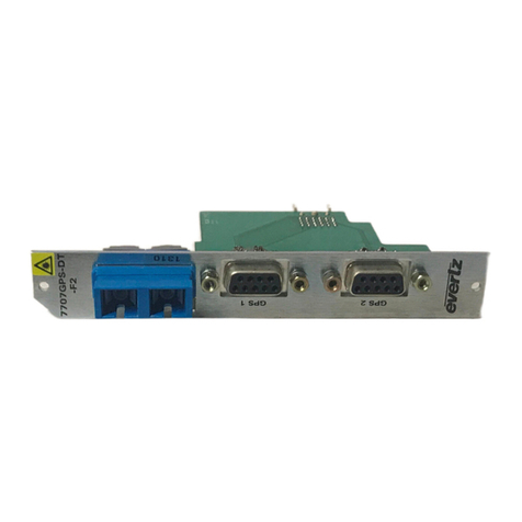
evertz 7707GPS-DT User manual

evertz
evertz 7708GT-4 User manual

evertz
evertz 7707VB-4-ASI-OC3 User manual

evertz
evertz 7700 Series User manual

evertz
evertz 7707VB-8-ASI-OC3 User manual