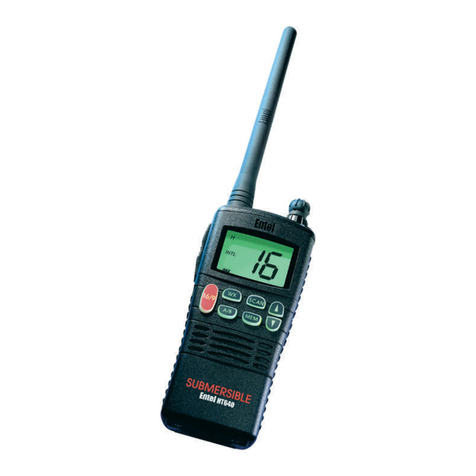
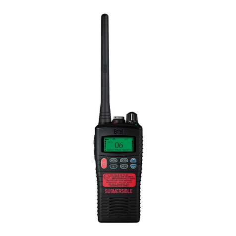
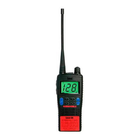
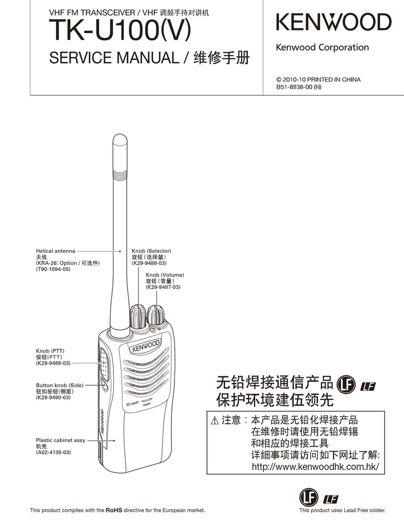
Entel HT700 2.0 Series User manual

Page 2 of 93
CONTENTS
1. INTRODUCTION ..........................................................................................................................5
1.1. M
ODEL
N
UMBERS
....................................................................................................................5
2. ITEMS SUPPLIED........................................................................................................................5
2.1. ACCESSORIES.....................................................................................................................6
3. OPERATING THE RADIO............................................................................................................7
4. THEORY OF OPERATION...........................................................................................................7
4.1. THE
MICROPROCESSOR....................................................................................................7
4.1.1. Microprocessor I/O Signals.............................................................................................8
4.1.2. Switch Operation ............................................................................................................8
4.1.3. Backlights.......................................................................................................................9
4.1.4. Microprocessor Clock and Beat Shift Function................................................................9
4.1.5. Microprocessor Reset.....................................................................................................9
4.1.6. Discrete Control Signals ...............................................................................................10
4.2. AUDIO
AND
TONE
SIGNALLING
CIRCUITS.......................................................................11
4.2.1. Received Voice Audio Processing................................................................................11
4.2.2. Received Tone Processing...........................................................................................12
4.2.3. Transmit Audio Processing...........................................................................................12
4.2.4. Transmit Tone Processing............................................................................................13
4.3. SYNTHESIZER
SECTION...................................................................................................14
4.3.1. Reference Oscillator.....................................................................................................14
4.3.2. Voltage Doubler............................................................................................................15
4.3.3. Loop Filter.....................................................................................................................15
4.3.4. Transmit VCO...............................................................................................................15
4.3.5. Receive VCO................................................................................................................15
4.3.6. VCO Power Switching and Buffering.............................................................................16
4.4. RECEIVER
SECTION..........................................................................................................17
4.4.1. Antenna Transmit/Receive switching circuit..................................................................17
4.4.2. First RF Filter................................................................................................................17
4.4.3. RF Amplifier..................................................................................................................17
4.4.4. Second RF Filter...........................................................................................................18
4.4.5. Mixer Circuit..................................................................................................................18
4.4.6. First IF Filter .................................................................................................................18
4.4.7. First IF Amplifier Circuit.................................................................................................18
4.4.8. Second LO Tripler Circuit..............................................................................................18
4.4.9. Second IF Circuit (FM IF IC).........................................................................................19
4.4.10. Noise Squelch Detector.............................................................................................19
4.5. TRANSMITTER
SECTION...................................................................................................21
4.5.1. Low Power Transmit Amplifier ......................................................................................21
4.5.2. Transmit Driver Amplifier ..............................................................................................21
4.5.3. Final Power Amplifier....................................................................................................21
4.5.4. PA Switching Circuit. ....................................................................................................22
4.6. POWER
SUPPLY................................................................................................................23
4.6.1. Battery connections and Protection circuit ....................................................................23
4.6.2. Main Regulator .............................................................................................................23
4.6.3. Transmit and Receive Power control circuit..................................................................23
4.7. MISCELLANEOUS
FUNCTIONS.........................................................................................23
4.7.1. Switches.......................................................................................................................23
4.7.2. Indicators......................................................................................................................23
4.7.3. Volume Control.............................................................................................................23
4.7.4. Battery Monitoring.........................................................................................................24
5. DISASSEMBLY..........................................................................................................................25
5.1. A
TTACHING AND
R
EMOVING THE
B
ATTERY
P
ACK
.....................................................................25

Page 3 of 93
5.2. D
ISASSEMBLING THE RADIO
................................................................................................. 25
5.3. R
EASSEMBLING THE RADIO
.................................................................................................. 26
5.4. V
ISUAL AND
M
ECHANICAL
I
NSPECTION
................................................................................. 26
6. TESTING AND PROGRAMMING SETUP..................................................................................27
7. SPECIFICATIONS......................................................................................................................28
8. PARTS LISTS ............................................................................................................................29
8.1. C
ONTROLLER AND
P
ROCESSOR
PEC
P
ARTS
L
IST
................................................................ 29
8.2. RF
PEC
P
ARTS
L
IST
-
HT72
X
VHF
MODELS
....................................................................... 33
8.3. RF
PEC
P
ARTS
L
IST
-
HT78
X
UHF
MODELS
...................................................................... 38
8.4. RF
PEC
P
ARTS
L
IST
-
HT71
X
66-88MH
Z MODELS
............................................................. 44
8.5. M
ECHANICAL
P
ARTS
L
IST
A
ND
E
XPLODED
V
IEW
–
HT7
X
2
M
ODELS
...................................... 49
8.6
M
ECHANICAL
P
ARTS
L
IST
A
ND
E
XPLODED
V
IEW
–
HT7
X
3
M
ODELS
.........................................53
8.7. M
ECHANICAL
P
ARTS
L
IST
A
ND
E
XPLODED
V
IEW
–
HT7
X
5
M
ODELS
...................................... 57
8.8. M
ECHANICAL
P
ARTS
L
IST
A
ND
E
XPLODED
V
IEW
–
HT7
X
6
M
ODELS
...................................... 61
8.9. M
ECHANICAL
P
ARTS
L
IST
A
ND
E
XPLODED
V
IEW
–
C
OMMON
T
O
A
LL
M
ODELS
....................... 65
9. CIRCUIT DIAGRAMS.................................................................................................................69
FIGURES
Figure 4.1 Synthesizer Block Diagram...............................................................................................14
Figure 4.2 Receiver Block Diagram....................................................................................................17
Figure 5.1 Exploded View.................................................................................................................25
Figure 6.1 Test & Programming Setup...............................................................................................27
Figure 7.1 Specifications....................................................................................................................28
Figure 9.1 Controller and Processor PEC Circuit Diagram Sheet 1 – All Models................................70
Figure 9.2 Controller and Processor PEC Circuit Diagram Sheet 2 – All Models................................71
Figure 9.3 Controller and Processor PEC Circuit Diagram Sheet 3 – All Models................................72
Figure 9.4 RF PEC Block Diagram – All Models ................................................................................73
Figure 9.5 Synthesiser Circuit Diagram – VHF Models ......................................................................74
Figure 9.6 VCO Circuit Diagram – VHF Models.................................................................................75
Figure 9.7 Receiver Circuit Diagram – VHF Models...........................................................................76
Figure 9.8 Transmitter Circuit Diagram – VHF Models.......................................................................77
Figure 9.9 Synthesiser Circuit Diagram – UHF Models......................................................................78
Figure 9.10 VCO Circuit Diagram – UHF Models...............................................................................79
Figure 9.11 Receiver Circuit Diagram – UHF Models.........................................................................80
Figure 9.12 Transmitter Circuit Diagram – UHF Models.....................................................................81
Figure 9.13 Synthesiser Circuit Diagram – 66-88MHz Models ...........................................................82
Figure 9.14 VCO Circuit Diagram – 66-88MHz Models......................................................................83
Figure 9.15 Receiver Circuit Diagram – 66-88MHz Models................................................................84
Figure 9.16 Transmitter Circuit Diagram – 66-88MHz Models............................................................85
Figure 9.17 HT72x RF Board, TOP VIEW..........................................................................................86
Figure 9.18 HT72x RF Board, BOTTOM VIEW............................................................................... 87
Figure 9.19 HT78x RF Board, TOP VIEW..........................................................................................88
Figure 9.20 HT78x RF Board, BOTTOM VIEW..................................................................................89
Figure 9.21 HT71x RF Board, TOP VIEW..........................................................................................90
Figure 9.22 HT71x RF Board, BOTTOM VIEW .................................................................................91
Figure 9.23 HT7Xx Control, TOP VIEW..……………………………………………..…………………….92
Figure 9.24 HT7Xx Control Board, BOTTOM VIEW ……………………………...………………………93

Page 4 of 93
TABLES
Table 2.1 Items Supplied .....................................................................................................................5
Table 2.2 Accessories..........................................................................................................................6
Table 4.1 Microprocessor Input Signals...............................................................................................8
Table 4.2 Microprocessor Output Signals ............................................................................................8

Page 5 of 93
1. INTRODUCTION
The Entel HT700 Series 2 is a PMR handheld two-way VHF/UHF transceiver. It is of heavy
duty, commercial grade construction exceeding MIL-STD 810/C/D/E/F, with up-rated IP55
splash proof protection.
It is constructed with a microprocessor controlled, temperature compensated Phase Locked
Loop (PLL) frequency synthesizer. Depending on the version, it has either 16 or 255
programmable channels. Some versions also have an LCD display and Keypad.
The radio features a double conversion receiver and a direct FM transmitter modulator.
A special integrated circuit provides support for sub-audible signalling (all CTCSS & DCS
tones).
The transceiver includes the following features:
•Scan mode.
•Four programmable buttons.
•VOX (voice operated transmit).
•Easy-to-read LCD display (depending on version).
•EEPROM memory back-up.
•Stored and/or Keypad DTMF dialling (depending on version).
The battery uses Lithium-ion technology for long life. The Battery system also incorporates a
battery level indicator, a low battery warning bleep/flashing LED, and a built in charge cycle
counter.
The Radio also has an extensive range of accessories.
1.1. Model Numbers
The HT700 Series 2 transceivers are available in many different configurations. Advanced
functions will also depend on model type. Part Number Identification is as follows:
HT72x are VHF models.
HT78x are UHF models.
HT71x are 66-88MHz models
HT7x2 have no display or keypad
HT7x3 have an LCD display but no keypad
HT7x5 have an LCD display and simple 8 button keypad
HT7x6 have an LCD display and full 20 button keypad
2. ITEMS SUPPLIED
Items Model Quantity
Radio HT7xx 1
Antenna CATxx 1
1800mAh Li-Ion battery pack CNB750E 1
Spring loaded belt clip CBT750 1
Intelligent rapid charger* CSAHT 1
User guide UG700 1
Table 2.1 Items Supplied
* CSAHT (only supplied with HT7x2, HT7x2S & HT7x3 models)

Page 6 of 93
2.1. ACCESSORIES
The HT700 Series is supported by a wide range of useful accessories.
For an up to date list visit the Entel web site at www.entel.co.uk
CSAHT 1-way dual slot rapid charger, 110/230v operation
CSBHT 6-way dual slot rapid charger, 110/230v operation
CFC750 Soft leather carry case with strap & Belt loop
CFC756 Soft leather carry case with strap & Belt loop
CLC752 Hard leather carry case with strap & Belt loop
CLC753 Hard leather carry case with strap & Belt loop
CLC756 Hard leather carry case with strap & Belt loop
CBT750 Spring loaded belt clip
CMPI/750 Compact medium duty speaker microphone with earpiece jack
CMP750 Heavy duty submersible speaker microphone
EHP9 D-shaped earpiece (plugs into CMP1/750 or CMP750 above)
Tattoo Lightweight Bluetooth earpiece/microphone
X3 Durable, water resistant Bluetooth earpiece/microphone
M10 Ultra small Bluetooth earpiece/microphone
BTPPT Small Bluetooth remote press to talk button
EA12/750 D-shaped earpiece with in-line PTT/microphone & VOX*
EA15/750 Earpiece microphone with transparent acoustic tube & VOX*
EA19/750 D-shaped earpiece with boom microphone and in-line PTT & VOX*
EPH750 D-Shaped earpiece (connects directly to radio)
EPT40/750 Bone conductive earpiece microphone with PTT
CXR5/750 Bone conductive skull microphone with in-line PTT
CXR16/750 D-shaped earpiece and throat microphone with in-line PTT
CHP1/750 Light weight single earpiece headset with in-line PTT &VOX*
CHP750HS Single earpiece ear defender headset with boom Mic and in-line PTT for hard
hat &VOX*
CHP750HD Double earpiece defender headset with boom Mic and in-line PTT for hard hat
&VOX*
CHP750D Double earpiece headband defender headset with boom Mic and in line PTT
&VOX*
CHP750BT Bluetooth double earpiece headband defender headset with boom Mic and ear
cup PTT
* VOX = Voice Operated Transmit (hands free operation)
CXW640 Antenna adapter for external aerial connection
CAT20 Helical antenna VHF
CAT80 Whip antenna UHF
CAT80VS Stubby antenna UHF
CAT710-78 78MHz compressed antenna
CAT710-85 85MHz compressed antenna
CAT710-Full/Y 66-77MHz full length antenna
CAT710-Full/G 77-88MHz full length antenna
CAT700-40 30-50MHz antenna
Table 2.2 Accessories
This manual suits for next models
7
Table of contents
Other Entel Transceiver manuals

Entel
Entel HX402 User manual
Entel
Entel HT900T Series User manual

Entel
Entel HX446E User manual
Entel
Entel HT644 GMDSS User manual
Entel
Entel HT702 User manual
Entel
Entel HX446E User manual
Entel
Entel HT840 User manual
Entel
Entel HT952 User manual
Entel
Entel HT981 User manual

Entel
Entel HX402 HX422 User manual

Entel
Entel HT542 User manual

Entel
Entel EURO-WAVE User manual

Entel
Entel HT9506 User manual
Entel
Entel HT642 User manual

Entel
Entel HX400 series User manual
Entel
Entel HT700 Series User manual
Entel
Entel DX Land Series Setup guide
Entel
Entel HT712T User manual
Entel
Entel HT644 GMDSS User manual
Entel
Entel HT644 Series Setup guide

