Enthermics DC250L User manual
Enthermics Medical Systems
An ISO 13485:2016 certified company
W164 N9221 Water St |Menomonee Falls WI 53051
Tel 262-251-8356 |800-TO-B-WARM
www.enthermics.com
Printed in the U.S.A. Specifications are subject to change without notice. Made in the U.S.A.
Owner’s Manual
MN-39216 • Rev 3 • 12/18
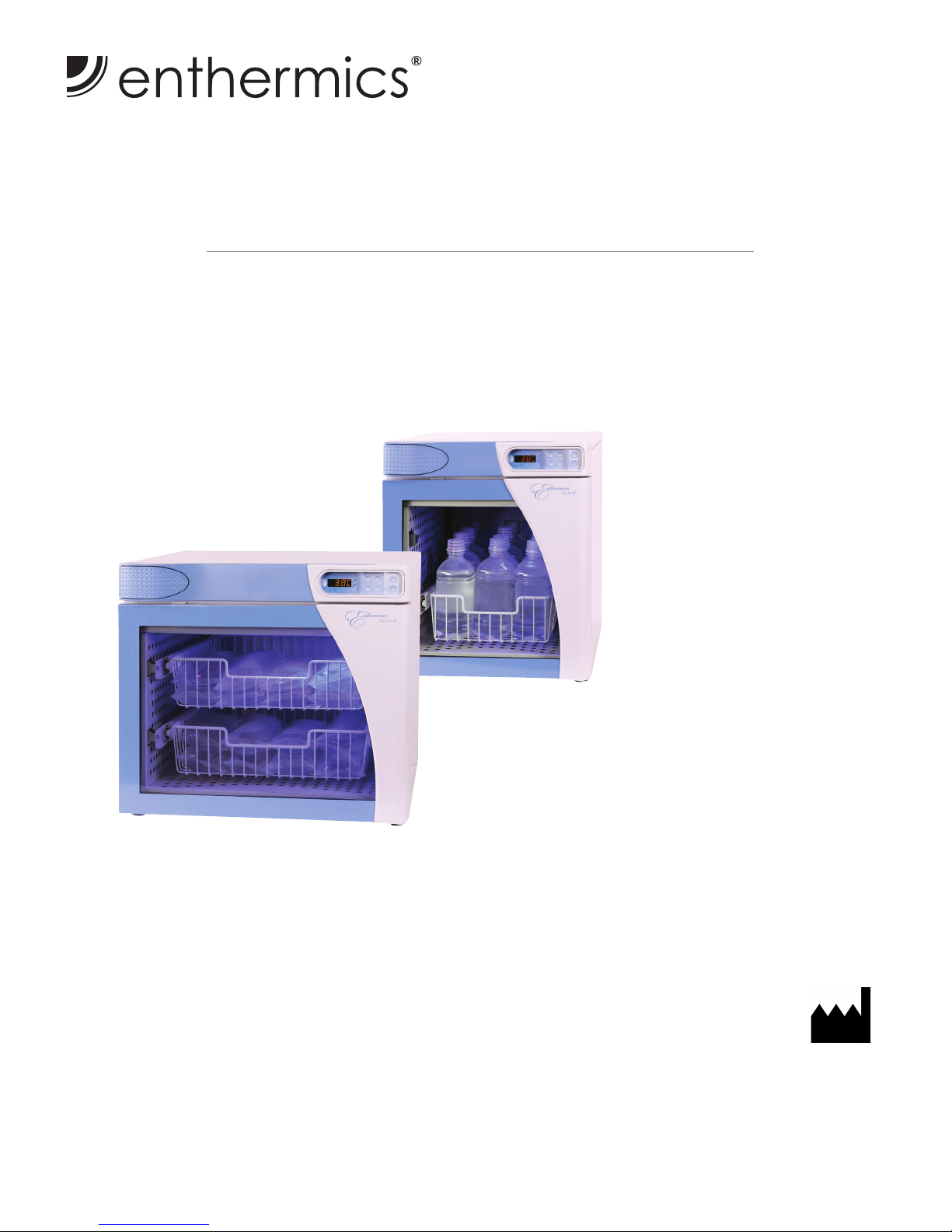
Fluid Warming Cabinet
DC250L
DC400L
120V
DC250L shown with
single basket insert
DC400L
MN-39216 • Rev 3 • 12/18 • DC Series Fluid Warmer
Table of Contents
Environmental Conditions ......................... 3
Receipt of Appliance .............................. 3
Transportation Damage and Claims ................. 3
Unpacking....................................... 4
Safety Procedures ................................ 5
Installation
Specications and Features ...................... 6
Electrical Information........................... 7
Electromagnetic Compatibility Data ............... 8
Preparation................................... 10
Operating Instructions
Using the Fluid Controller ...................... 11
Operating the Fluid Warmer .................... 13
Capacity ..................................... 13
Cleaning and Preventative Maintenance
Protecting Surfaces ............................ 14
Cleaning Agents............................... 14
Cleaning Materials............................. 14
How to Clean the Appliance ..................... 14
Preventative Maintenance Checklist .............. 15
Dimension Drawings ............................. 16
Troubleshooting Guide ........................... 18
Service
How to Replace the Fuse........................ 20
How to Manually Reset the Warmer .............. 20
Options and Accessories ........................ 21
Zone Heating Element Locations................. 21
Parts Lists and Drawings........................ 22
Wire Diagram ................................... 28
Refer to wire diagram included with the uid warmer.
Authorized Representative:
MDSS GmbH
Schiffgraben 41
30175 Hannover
Germany
REPEC
3
MN-39216 • Rev 3 • 12/18 • DC Series Fluid Warmer
Delivery
Receipt of Appliance
The appliance has been thoroughly tested and
inspected to ensure only the highest quality appliance is
provided. Upon receipt, inspect for any possible shipping
damage and report it at once to the delivering carrier.
See Transportation Damage and Claims section.
This appliance, complete with unattached items and
accessories, may be delivered in one or more packages.
Conrm that all standard items and options have been
received with each appliance as ordered. Save all the
information packed with the appliance.
Register the appliance online to assure prompt service in
the event of a warranty parts and labor claim.
http://www.enthermics.com/warranty-registration
The serial number is required for all inquiries.
Always include both model and serial number(s) in any
correspondence regarding the appliance.
Model: ______________________________________________
Serial number: ______________________________________________
Purchased from: ______________________________________________
Date installed: ____________________ Voltage: ____________
Environmental Conditions
Transport and storage environmental conditions (not to exceed 15 days)
Ambient temperature range of -40°C to +70°C (-40°F to +159°F)
Relative humidity range of 10% to 95%, non-condensing
Atmospheric pressure range of 50kPa to 106kPa
Operational environmental conditions
The appliance must acclimate to the room temperature in the environment it will be placed—24 hours
is recommended.
The recommended environmental temperature range is 15°C to 32°C (60°F to 90°F). The dierence between the room
temperature and the set-point temperature must be greater than 11°C (20°F).
The recommended relative humidity is above 20%, non-condensing.
Indicates that the package contents should
not be used if the package has been
damaged or opened.
All Enthermics Medical Systems warmers
are sold Free on Board (F.O.B.) shipping
point, and when accepted by the carrier,
such shipments become the property of the
consignee.
Should damage occur in shipment, do not put the warmer
into service until the damage has been inspected by an
authorized service provider.
Should damage occur in shipment, it is a matter between
the carrier and the consignee. In such cases, the carrier
is assumed to be responsible for the safe delivery of the
merchandise, unless negligence can be established on the
part of the shipper.
1. Conduct an immediate inspection while the warmer
is still in the truck or immediately aer it is moved to
the receiving area. Do not wait until aer the warmer
is moved to a storage area.
2. Do not sign a delivery receipt or a freight bill until
a proper count has been made and inspection of all
warmers are received.
3. Note all damage to packages directly on the carrier’s
delivery receipt.
4. Have the driver sign the delivery receipt. If the
driverrefuses to sign, make a notation of this refusal
on the receipt.
5. If the driver refuses to allow inspection, write the
following on the delivery receipt: Driver refuses to
allow inspection of containers for visible damage.
6. Contact the carrier’s oce immediately upon nding
damage and request an inspection. Mail a written
conrmation to the carrier’s oce with the time,
date, and the person called.
7. Save any packages and packing material for further
inspection by the carrier.
8. Promptly le a written claim with the carrier and
attach copies of all supporting paperwork.
Enthermics will continue our policy of assisting our
customers in collecting claims which have been properly
led and actively pursued. Enthermics cannot, however,
le any damage claims, assume the responsibility of any
claims, or accept deductions in payment for such claims.
Transportation Damage and Claims
4MN-39216 • Rev 3 • 12/18 • DC Series Fluid Warmer
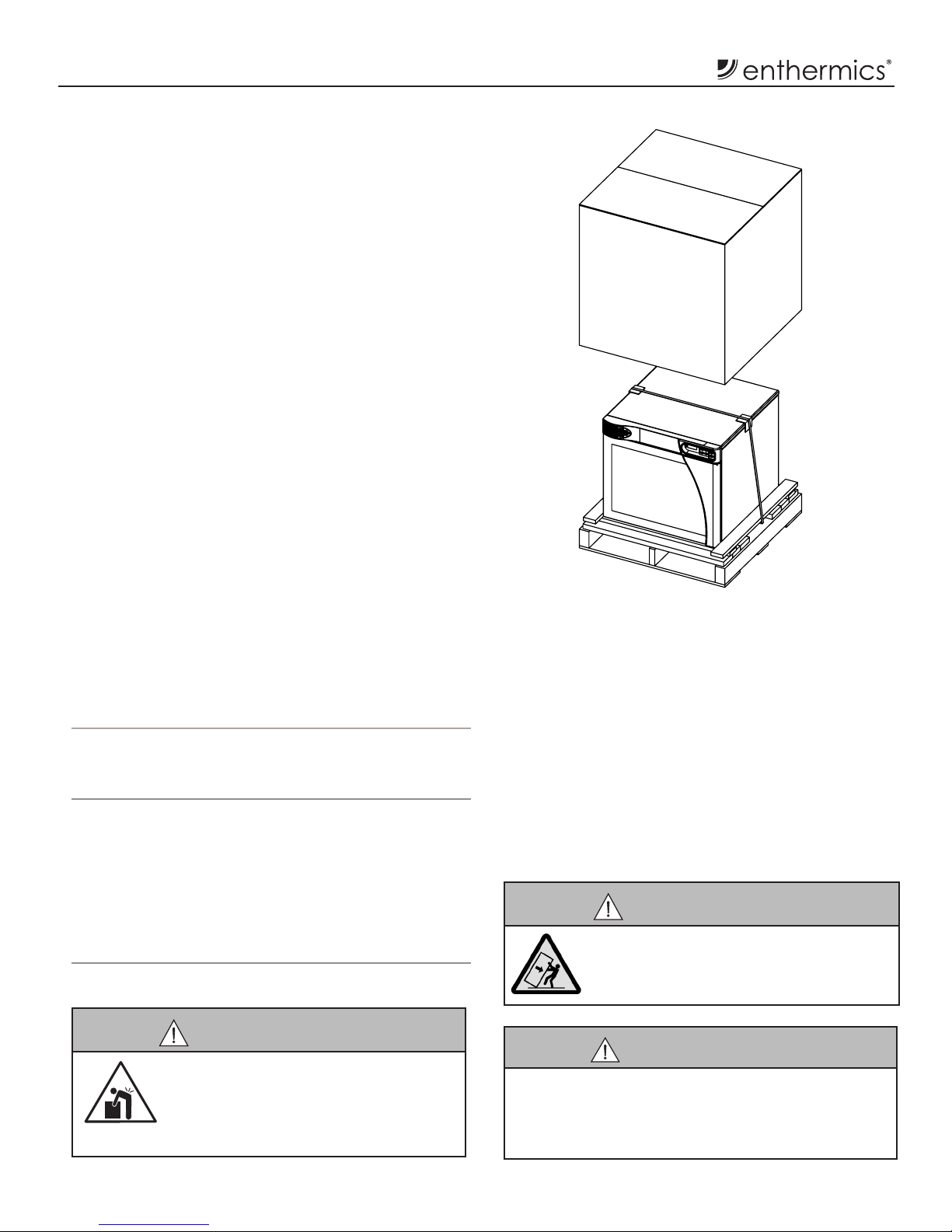
Unpacking
1. Remove the warmer from the carton or crate.
NOTE: Do not discard the carton and other
packaging material until the warmer has
been inspected for hidden damage and
tested for proper operation.
Do not discard this manual. This manual
is considered to be part of the warmer
and is to be provided to the owner or
manager of the business or to the person
responsible for training operators.
Additional manuals are available from
the service department.
2. Read all instructions in this manual carefully before
initiating the installation of this warmer, using the
warmer or performing routine maintenance. Following
procedures other than those indicated in this manual to
use and clean the warmer is considered inappropriate
and may cause damage, injury or fatal accidents, in
addition to invalidating the warranty and relieving the
manufacturer of all liability.
3. Before connecting warmer to electrical power
a) Remove all protective plastic lm and packaging
material from the outside of the warmer
b) Remove all packaging material from the inside of
the warmer.
c) Remove packaging material from accessories and
store accessories in a convenient place for future
use.
4. Slowly roll the warmer across high thresholds.
CAUTION
The door may swing during transport. Only
transport the appliance when the door is
closed and secure.
CAUTION
Appliance and accessories may be
heavy. To prevent serious injury, always
use a sufficient number of trained and
experienced workers when moving or
leveling appliance and handling accessories.
CAUTION
To prevent injury or property damage:
Always apply both caster brakes on mobile carts,
appliances, or accessories when stationary.
Appliances on casters can move or roll on uneven floors.
Dimensions (HxWxD)
DC250L: 21.9" x 18.4" x 25.8" (557mm x 470mm x 630mm)
DC400L: 21.9" x 24.0" x 27.1" (557mm x 610mm x 688mm)
Weight**
DC250L: Net: 85 lbs (39 kg) Ship: 135 lbs (61 kg)
Shipping dimensions: 22" L x 35" W x 29" H
559 x 889 x 737mm
DC400L: Net: 100 lbs (45 kg) Ship: 165 lbs (75 kg)
Shipping dimensions: 31" L x 31" W x 30" H
878 x 787 x 762mm
**Domestic ground shipping information. Contact the manufacturer
for export weight and dimensions.
5
MN-39216 • Rev 3 • 12/18 • DC Series Fluid Warmer
Safety Procedures
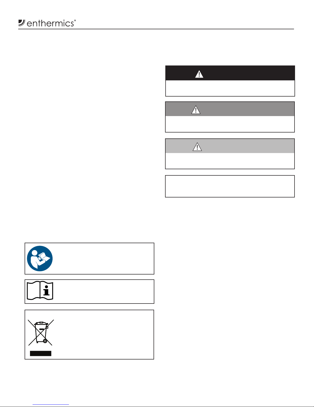
DANGER
Indicates a hazardous situation that, if not avoided, will
result in death or serious injury.
NOTICE: Indicates information considered important,
but not hazard-related (e.g., messages relating
to property damage).
Knowledge of proper procedures is essential to the
safe operation of electrically and/or gas energized
equipment. The following signal words and symbols
may be used throughout this manual.
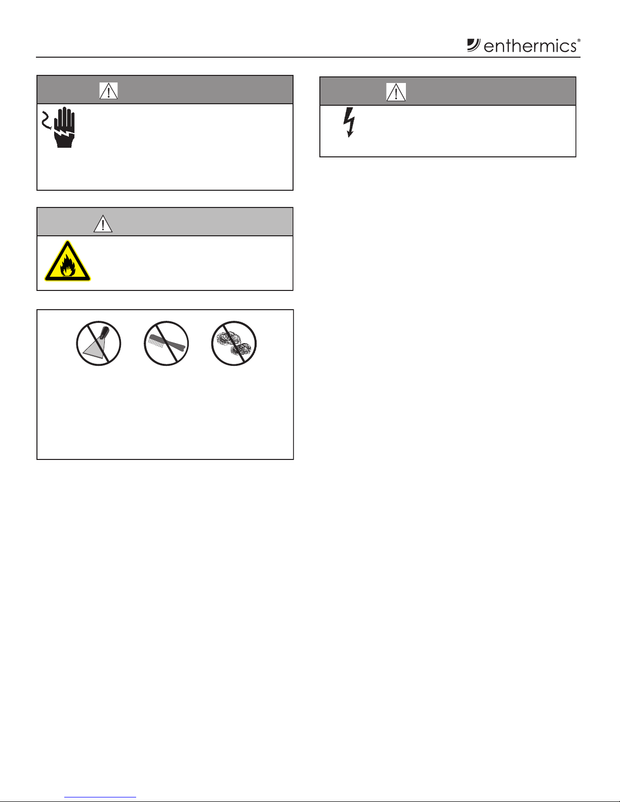
Indicates that referral to operating
instructions is a mandatory action. If
not followed the operator could suffer
personalinjury.
Indicates that referral to operating
instructions is recommended to understand
operation of equipment.
WARNING
Indicates a hazardous situation that, if not avoided, could
result in death or serious injury.
CAUTION
Indicates a hazardous situation that, if not avoided, could
result in minor or moderate injury.
NOTICE: For equipment delivered for use in any
locationregulatedby thefollowing directive:
2012/95/EC WEEE
Do not dispose of electrical or electronic
equipment with other municipal waste.
• The uid warming cabinet is only intended for
warming medical solutions for irrigation and
injection prior to use. Refer to the labeling of the
manufacturer of the products to be warmed regarding
the recommended temperature and the duration of
warming. No other use for this appliance is authorized
or recommended.
• This uid warming cabinet is intended for use in
commercial establishments where all operators are
familiar with the purpose, limitations, and associated
hazards of this device. The uid warming cabinet
can be used wherever there is appropriate space and
electrical source including patient support areas,
ER, ICU, PACU, surgical suites, patient rooms, and
nursing stations. Do not use the uid warming cabinet
in the presence of ammable anesthetic mixtures
(with air, oxygen, or nitrous oxide).
• Operating instructions and warnings must be read
and understood by all operators and users.
• Any troubleshooting guides, component views, and
parts lists included in this manual are for general
reference only and are intended for use by qualied
and trained technicians.
• This manual should be considered a permanent
part of this appliance. This manual and all supplied
instructions, diagrams, schematics, parts lists,
notices, and labels must remain with the device if the
item is sold or moved to another location.
6MN-39216 • Rev 3 • 12/18 • DC Series Fluid Warmer
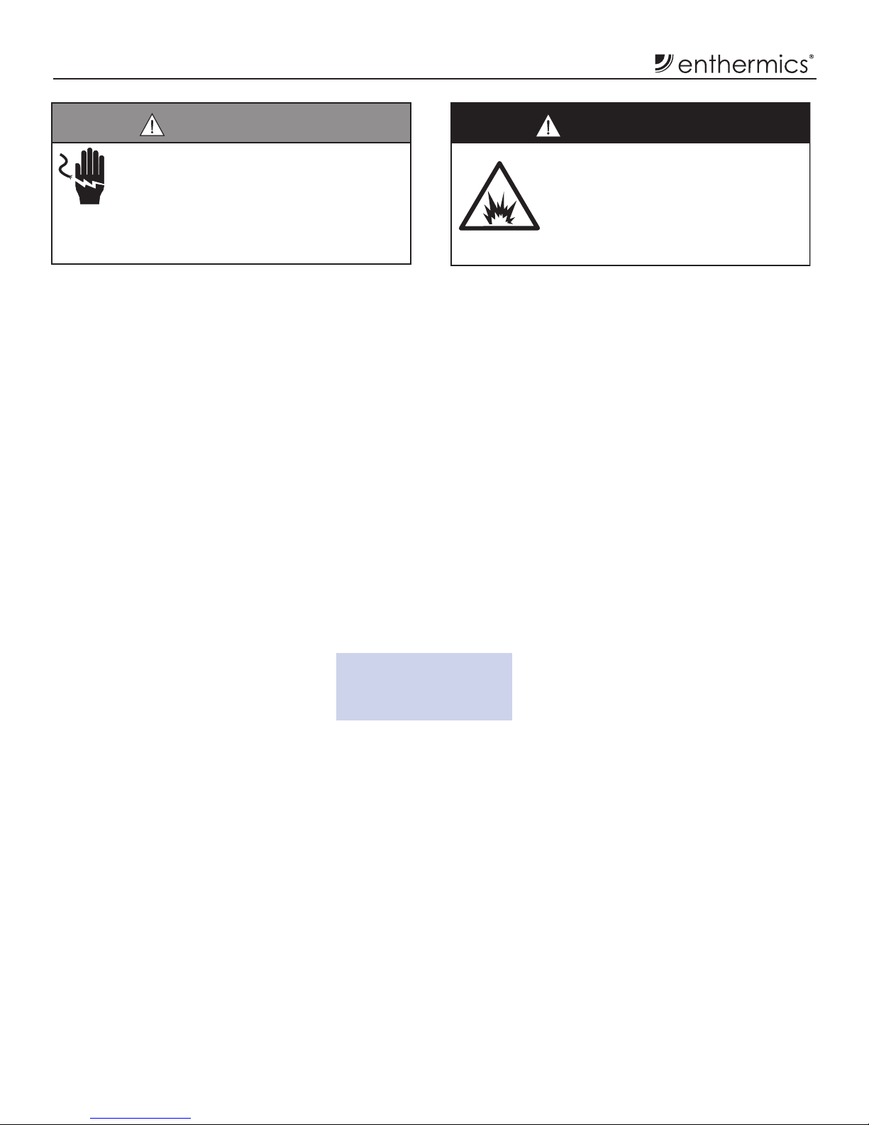
Installation
WARNING
To prevent serious personal injury, death, or
property damage:
Do not steam clean, hose down or flood the
interior or exterior with water or liquid solution
of any kind. Do not use water jet toclean. Failure
to observe this precaution will void the warranty.
DANGER
To prevent serious personal injury, death,
or property damage:
Do not use this warmer in the presence of
flammable anesthetic mixtures (with air
or with oxygen or nitrous oxide).
Not category AP or APG equipment
Specifications:
• Single-chamber warming cabinet.
• White epoxy-coated steel exterior
casing and interior insert.
• Single pane, energy-ecient,
e-coated glass window in the door
allows inventory observation.
• Push-button door for
hands-free operation.
• Door is fully gasketed and hinged
on the right side of the unit.
• WarmSafe™ incorporates a multiple
zone warming technology (Patent No:
US 8,217,316; US 8,581,152) that
heats where and when it is needed.
All interior surface temperatures
are monitored, providing an
ecient balance of heat, low-energy
consumption and minimal heat loss.
• Four (4) non-skid rubber feet
are standard.
Controller:
• Adjustable temperature range of
» 32°-40°C (90°-104°F) adjustable
injection mode
» 32°-66°C (90°-150°F) adjustable
irrigation mode
• Accurate temperature
»IRR +0/-1.67°C (-3°F)
»INJ +0/-1.10°C (-2°F)
• Operates in Celsius or Fahrenheit.
• LED display.
• Built-in speaker for audible feedback.
• Integrated control lockout feature.
Additional features:
• LED interior lighting casts a comforting
blue glow with two (2) dierent intensity
settings and o mode.
• Safety: The controller stores all settings
and resumes operation using these
settings in the event of a power failure.
When the power is restored, the
controller sounds an alarm. The on/o
status indicator ashes.
• Safety: A warming shut-o system,
separate from the controller,
prevents overheating.
• Convenience: Access point and
removable cover on the back panel
allows the addition of data logging or
temperature management hardware.
• Convenience: Stackable congurations
are available for additional uid capacity
or to pair with blanket warmers.
Clearance requirements:
3" (76mm) from rear
1" (25mm) from top and sides
3/4" (19mm) from bottom
Specications and Features
7
MN-39216 • Rev 3 • 12/18 • DC Series Fluid Warmer
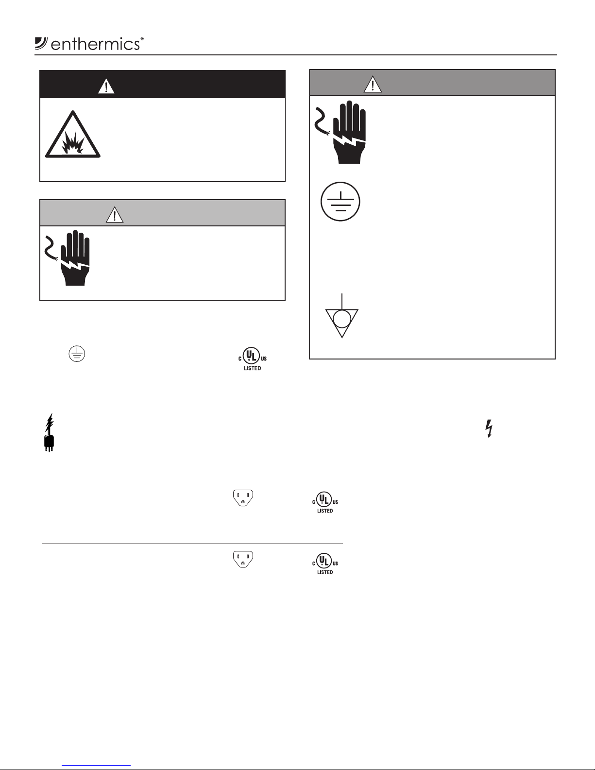
Electrical Information
Locate the Rating Tag
Verify the power requirements for the appliance. The power specication is located on the
appliance identication rating tag. This tag is permanently attached to the appliance.
Hazardous
Voltage Present
CAUTION
Power source must match voltage identified
on appliance rating tag. The rating tag
provides essential technical information
required for any appliance installation,
maintenance or repairs. Do not remove,
damage or modify the rating tag.
DANGER
To prevent serious personal injury, death,
or property damage:
Do not use this warmer in the presence of
flammable anesthetic mixtures (with air
or with oxygen or nitrous oxide).
Not category AP or APG equipment
Safety Class I
Equipment
Protective Earth
Ground Symbol
Medical Equipment classied by Underwriters
Laboratories with Respect to Electrical Shock,
Fire and Mechanical Hazards only, in Accordance
with UL 61010–1 and CAN/CSA C22.2 No. 61010–1. E471516
Grounding reliability can only be achieved when appliance is
connected to an equivalent receptacle marked “Hospital Grade.”
Wire diagram is located under top lid of appliance.
Power Requirements
WARNING
To prevent serious injury, death, or
property damage:
All electrical connections must be
made by a qualified and trained service
technician in accordance with applicable
electrical codes.
This appliance must be adequately
grounded in accordance with local
electrical codes or, in the absence of local
codes, with the current edition of the
National Electrical Code ANSI/NFPA No.
70. In Canada, all electrical connections
are to be made in accordance with CSA
C22.1, Canadian Electrical Code Part 1 or
local codes.
CE-approved appliances include an
equipotential-bonding terminal marked
with the symbol shown on the le.
Provisions for earthing are to be made in
accordance with IEC:2010 60335-1 section
27 or local codes.
120 V.A.C. — 60 Hz, 1 ph
0.7 kW, 5.8 Amps
Safety Class I Equipment
No Applied Parts
Mode of Operation: Continuous
NEMA 5-15P
15A - 125V Plug
Hospital Grade
IP-X0
E471516
120 V.A.C. — 60 Hz, 1 ph
0.7 kW, 5.8 Amps
Safety Class I Equipment
No Applied Parts
Mode of Operation: Continuous
NEMA 5-15P
15A - 125V Plug
Hospital Grade
IP-X0
E471516
DC250L:
DC400L:
NOTE: The fluid warming cabinet should not be le unattended for periods of
more than 24 hours. For absences longer than 24 hours, disconnect the
fluid warming cabinet for the power source.
8MN-39216 • Rev 3 • 12/18 • DC Series Fluid Warmer
Electrical Information
The warmer requires special precautions
regarding EMC (Electromagnetic
Compatibility) and needs to be installed
and put into service according to the
EMC information provided in the
accompanying documents.
Portable and mobile RF communications equipment can
aect medical electrical equipment.
A risk of increased emissions or decreased immunity
may result if the power cord attached is altered or a
manufacturer supplied power cable is not used.
The warmer should not be used adjacent to or stacked with
other equipment.
Observe to verify normal operation if it is necessary to use
adjacent to or stacked with other equipment.
The essential performance of the warmer is to not
exceed an internal temperature of 180°F / 82°C (+10%) for
blanket warmers or 150°F / 66°C (+10%) for uid warmers.
The warmers are intended for use in the electromagnetic environment specied below. The customer or the end user
of this warmer should assure that it is used in such an environment.
Emissions test Compliance Electromagnetic environment - guidance
RF emissions; CISPR 11 Group 1 The warmer uses RF energy only for internal function. Therefore,
its RF emissions are very low and are not likely to cause any
interference in nearby electronic equipment.
RF emissions; CISPR 11 Class B The warmer is suitable for use in all establishments, including
domestic establishments and those directly connected to the public
low-voltage power supply network that supplies buildings used for
domestic purposes.
Harmonic emissions; IEC 61000-3-2 Class A
Voltage uctuations/Flicker
emissions; IEC 61000-3-3
Complies
The warmer is intended for use in the electromagnetic environment specied below. The customer or the end user of
this warmer should assure that it is used in such an environment.
Immunity test IEC 60601 test level Compliance level Electromagnetic environment - guidance
Electromagnetic
discharge (ESD)
IEC 61000-4-2
±6 kV contact
±8 kV air
±6 kV contact
±8 kV air
Floors should be wood, concrete or ceramic tile.
If oors are covered with synthetic material, the
relative humidity should be at least 30%.
Electrical fast
transient/burst
IEC 61000-4-4
±2 kV for power
supply lines; ±1 kV
for input/output lines
+2 kV for power
supply lines
Main power quality should be that of a typical
commercial or hospital environment. The
warmer does not have any input/output lines.
Surge
IEC 61000-4-5
±1 kV dierential
mode; ±2 kV
common mode
±1 kV dierential
mode; ±2 kV
common mode
Mains power quality should be that of a typical
commercial or hospital environment.
Voltage dips, short
interruptions and
voltage variations on
power supply input lines
IEC 61000-4-11
<5 % UT (>95 % dip in
UT) for 0.5 cycle
40 % UT (60 % dip in
UT) for 5 cycles
70 % UT (30 % dip in
UT) for 25 cycles
<5 % UT (>95 % dip in
UT) for 5 sec
<5 % UT (>95 % dip
in UT) for 0.5 cycle
40 % UT (60 % dip
in UT) for 5 cycles
70 % UT (30 % dip
in UT) for 25 cycles
<5 % UT (>95 % dip
in UT) for 5 sec
Mains power quality should be that of a typical
commercial or hospital environment. If the user
of the warmer requires continued operation
during power mains interruptions, it is
recommended that the warmer be powered from
an uninterrupted power supply or a battery.
Power frequency (50/60
Hz) magnetic eld
IEC 61000-4-8
3 A/m 3 A/m Power frequency magnetic elds should be at
levels characteristic of a typical location in a
typical commercial or hospital environment.
NOTE:
UT is the a.c. mains voltage prior to application of the test level.
Guidance and Manufacturer’s Declaration
Electromagnetic Emissions
Electromagnetic Immunity
9
MN-39216 • Rev 3 • 12/18 • DC Series Fluid Warmer
Electrical Information
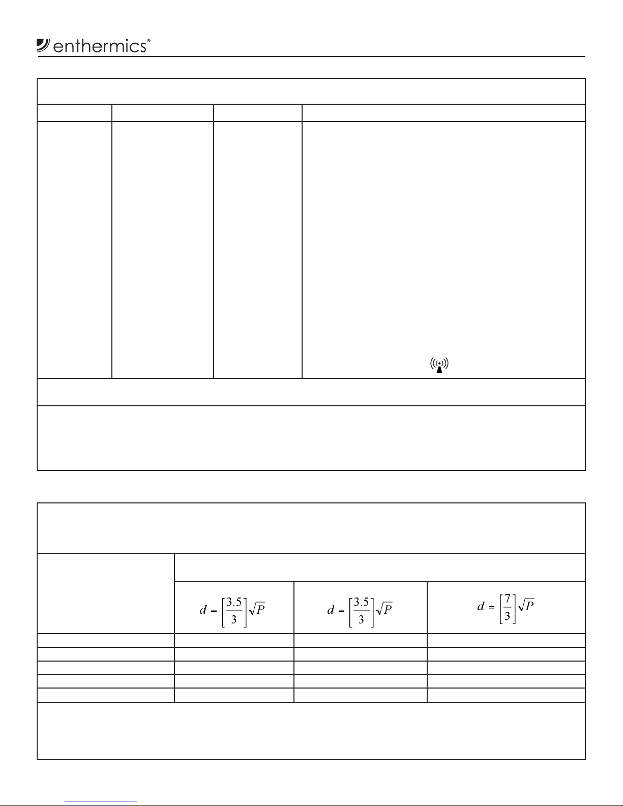
The warmer is intended for use in the electromagnetic environment specied below. The customer or the end user of
this warmer should assure that it is used in such an environment.
Immunity test IEC 60601 test level Compliance level Electromagnetic environment - guidance
Conducted RF
IEC 61000-4-6
Radiated RF
IEC 61000-4-3
3 V/m
150 kHz to 80 MHz
3 V/m
80 MHz to 2.5 GHz
3 V/m
3 V/m
Portable and mobile RF communications equipment should
be used no closer to any part of the warmer, including
cables, than the recommended separation distance
calculated from the equation applicable to the frequency of
the transmitter.
Recommended separation distance
d = [3.5/3] √P
d = [3.5/3] √P 80 MHz to 800 MHz
d = [7/3] √P 800 MHz to 2.5 GHz
where P is the maximum output power rating of the
transmitter in watts (W) according to the transmitter
manufacturer and d is the recommended separation distance
in meters (m).
Field strengths from xed RF transmitters, as determined
by an electromagnetic site survey,ashould be less than the
compliance level in each frequency range.b
Interference may occur in the vicinity of equipment marked
with the following symbol:
NOTE: 1. At 80 MHz and 800 MHz, the higher frequency range applies. 2. These guidelines may not apply in all situations.
Electromagnetic propagation is affected by absorption and reflection from structures, objects and people.
a. Field strengths from fixed transmitters, such as base stations for radio (cellular/cordless) telephones and land mobile radios, amateur radio, AM
and FM radio broadcast and TV broadcast cannot be predicted theoretically with accuracy. To assess the electromagnetic environment due to
fixed RF transmitters, an electromagnetic site survey should be considered. If the measured field strength in the location in which the warmer is
used exceeds the applicable RF compliance level above, the warmer should be observed to verify normal operation. If abnormal performance is
observed, additional measures may be necessary, such as reorienting or relocating the warmer.
b. Over the frequency range 150 kHz to 80 MHz, field strengths should be less than [VI] V/m.
The warmer is intended for use in an electromagnetic environment in which radiated RF disturbances are controlled.
The customer or the user of the warmer can help prevent electromagnetic interference by maintaining a minimum
distance between portable and mobile RF communications equipment (transmitters) and the warmer as recommended
below, according to the maximum output power of the communications equipment.
Rated maximum output
power of transmitter
W
Separation distance according to frequency of transmitter
m
150 kHz to 80 MHz 80 MHz to 800 MHz 800 MHz to 2.5 GHz
0.01 0.117 0.117 0.233
0.1 0.369 0.369 0.738
1 1.167 1.167 2.333
10 3.689 3.689 7.379
100 11.667 11.667 23.333
For transmitters rated at a maximum output power not listed above, the recommended separation distance d in meters (m) can be estimated using
the equation applicable to the frequency of the transmitter, where P is the maximum output rating of the transmitter in watts (W) according to the
transmitter manufacturer.
NOTE: 1. At 80 MHz and 800 MHz, the separation distance for the higher frequency range applies. 2. These guidelines may not apply
in all situations. Electromagnetic propagation is affected by absorption and reflection from structures, objects and people.
Electromagnetic Emissions
Electromagnetic Immunity Recommended Separation Distance Between Portable And Mobile
RF Communications Equipment And This Warmer

10 MN-39216 • Rev 3 • 12/18 • DC Series Fluid Warmer
Operation Instructions
NOTICE: A temporary odor may be noticeable upon initial
start-up of the warmer. Contact manufacturer
if the odor persists aer a day or more of
continuous use.
Cleaning Agents
Always use the proper cleaning agent at the
manufacturer’s recommended strength. Contact a local
cleaning supplier for product recommendations.
Preparation Before Operating the Warmer
1. Remove and wash any detachable items such as the
insert assembly with hot, soapy water. Dry the items
with a clean, lint-free cloth.
2. Clean the interior and exterior of the warmer with
a mild soap and water solution. Apply the solution
with a clean, damp cloth. Do not use commercial or
household cleaners that contain ammonia.
NOTE: Make sure to wipe the control panel, door vents,
door handle or door button, and door gaskets.
3. Remove all detergent residue from the interior and
exterior of the warmer with a clean, damp cloth.
4. Dry the interior and exterior of the warmer with a
clean, lint-free cloth. Leave the door open until the
interior is completely dry.
5. Sanitize the interior of the warmer with a sanitizing
solution. This solution must be approved for use on
stainless steel surfaces.
6. Clean the warmer glass with glass cleaner or
distilledvinegar.
7. Install the insert assembly.
11
MN-39216 • Rev 3 • 12/18 • DC Series Fluid Warmer
Operation Instructions
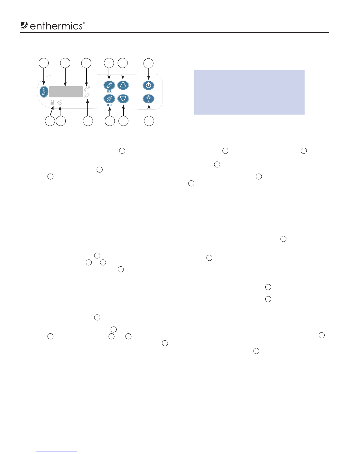
Using the Fluid Controller
1
8 79
10
1112
2 4
356
How to Set the Temperature Scale
1. While the uid controller is in the o mode, press and
hold the temperature recall button 1for
four (4) seconds.
2. Press the up arrow button 5or the down arrow
button 8to change to Fahrenheit (°F) or Celsius (°C).
How to Start the Fluid warming Cabinet
1. Connect the uid warming cabinet to an appropriate
hospital grade receptacle — specied on the electrical
information page.
2. Locate the circuit breaker on the back of the uid
warming cabinet.
3. Push the circuit breaker to the ON (I) position.
4. Press the ON/OFF button 6. The previous heating
mode status indicator 3or 10 illuminates and
temperature set-point is displayed 2.
How to Select the Heating Mode
1. Cool the uid compartment prior to switching from a
high temperature to a lower temperature to prevent an
unwanted over-temp alarm.
2. Press the ON/OFF button 6.
3. Press the irrigation uid button 4or the injection uid
button 9. The status indicator 3or 10 illuminates
and the previous temperature set-point is displayed 2.
How to Set the Operational Sound Volume
1. While the uid controller is on, press the temperature
recall button 1and the down arrow button 8
simultaneously. The current sound volume setting is
displayed 2.
2. Press the up arrow button 5
or the down arrow button
8to change the volume. Volume settings range from
0 (mute) to 12 (loud).
NOTE: The alarm volume is set at the maximum (12) and
cannot be disabled.
How to Display the Compartment
Temperature
1. Press the temperature recall button 1.
The temperature at the compartment sensor is
displayed 2for ve (5) seconds. Then the uid chamber
temperature set-point displays.
How to Adjust the Interior Lighting
1. Press the interior light button 7.
2. Press the interior light button 7again to change the
blue interior LED light to high, low, or o.
How to Clear an Over-Temperature Alarm
When the controller senses a temperature of 5° over the
temperature set-point the over-temperature indicator 11
will ash and an alarm will sound.
1. Press the ON/OFF button 6.
2. Allow the warmer to cool to the temperature set-point
to prevent an unwanted over-temp alarm.
3. Make sure the product inside the warmer is at the
correct temperature before using.
NOTE: If the alarm continues or reoccurs, the warmer needs to
be serviced.
Temperature Range:
• Irrigation (IRR) temperature range:
32°C to 66°C (90°F to 150°F)
• Injection (INJ) temperature range:
32°C to 40°C (90°F to 104°F)
12 MN-39216 • Rev 3 • 12/18 • DC Series Fluid Warmer
Operation Instructions
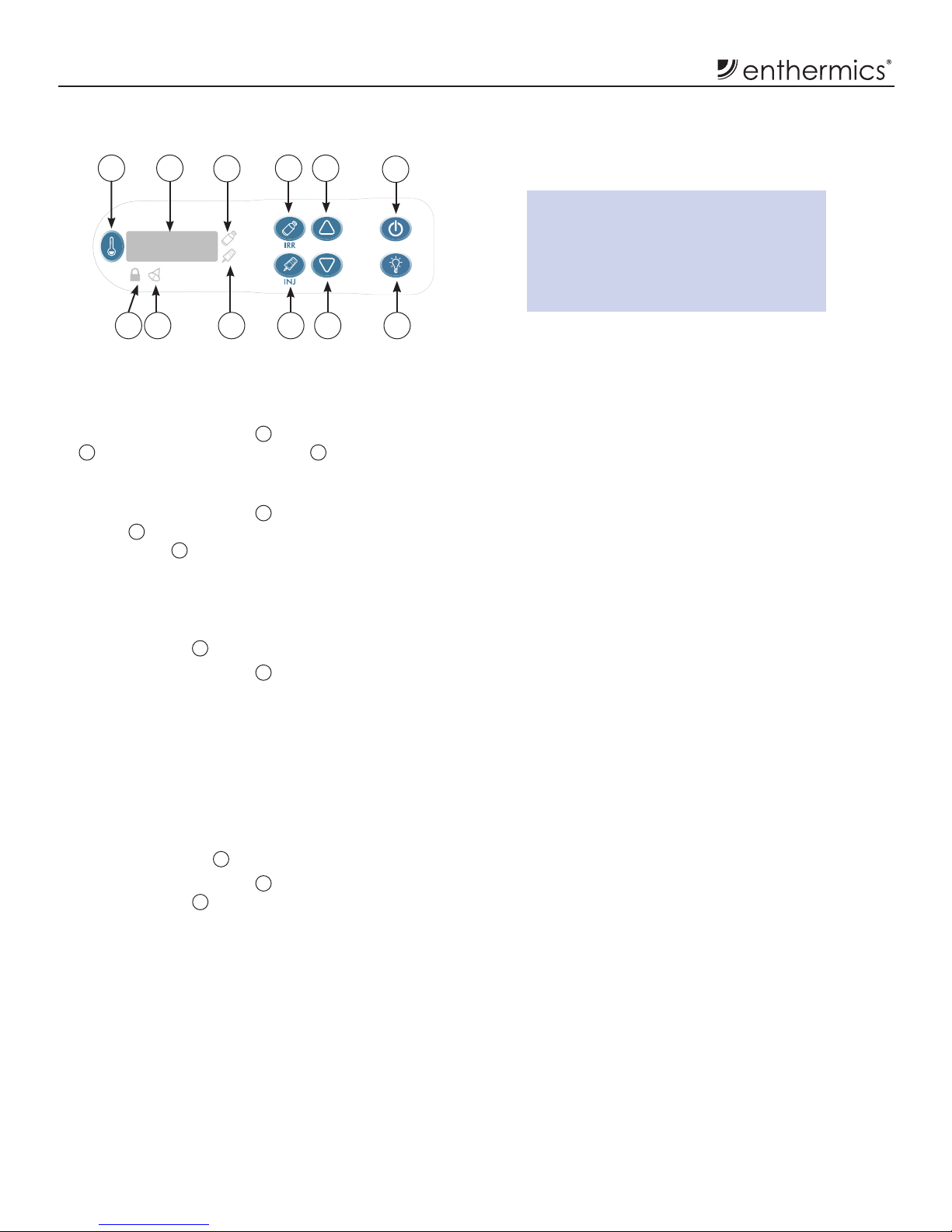
Using the Fluid Controller (continued)
How to Lock the Controller
The controller can be locked to prevent changes being
made to the temperature set-point or the mode selection.
1. Press the ON/OFF button 6and the up arrow button
5simultaneously. The lock icon 12 illuminates.
How to Unlock the Controller
1. Press the ON/OFF button 6and the down arrow
button 8simultaneously. The controller unlocks and
the lock icon 12 goes o.
How to Mute the Alarm
When the controller senses an alarm condition (see
troubleshooting guide), the controller sounds an alarm
and the alarm icon 11 ashes.
1. Press the ON/OFF button 6to acknowledge and mute
the alarm.
NOTE: If the alarm continues or reoccurs, the warmer needs
to be serviced.
Power Fail Detection
The controller stores all settings and resumes operation
using these settings in the event of a power failure. When
the power is restored, the controller sounds an alarm
once. The LED screen 2ashes.
1. Press the ON/OFF button 6.
The LED screen 2stops ashing.
NOTE: The controller displays the length of time of the
power outage in hours and minutes (hh:mm) for
five (5) seconds. Then the controller displays the set
operating temperature.
2. Make sure the product inside the warmer is at the
correct temperature before using.
Temperature Range:
• Irrigation (IRR) temperature range:
32°C to 66°C (90°F to 150°F)
• Injection (INJ) temperature range:
32°C to 40°C (90°F to 104°F)
1
8 79
10
1112
2 4
356
13
MN-39216 • Rev 3 • 12/18 • DC Series Fluid Warmer
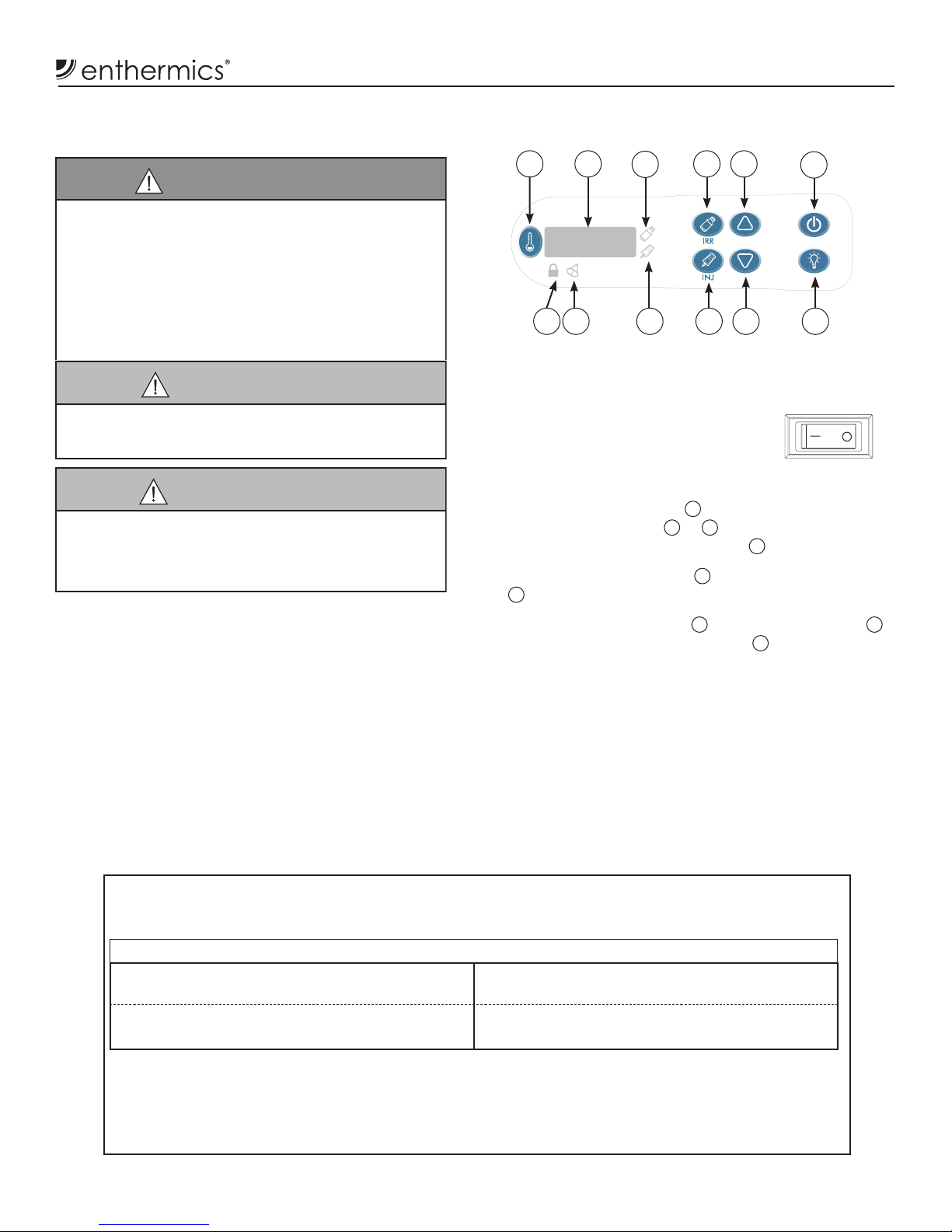
Operation Instructions
1. Connect the uid warming cabinet to an appropriate
hospital grade receptacle — specied on the electrical
information page.
2. Locate the circuit breaker on the back
of the uid warming cabinet.
3. Push the circuit breaker to the ON (I) position.
4. Press the ON/OFF button 6. The previous mode
of operation indicator 3or 10 illuminates and the
temperature set-point is displayed 2.
5. Press the irrigation button 4or the injection button
9to select the desired mode of operation.
6. Press the up arrow button 5or down arrow button 8
to adjust the temperature set-point 2.
NOTE: Cool the chamber prior to changing from a higher
temperature setting to a lower temperature setting
to prevent an unwanted alarm.
6. Make sure the uid chamber insert is installed.
7. Load the uid chamber with appropriate uid
containers.
8. Make sure the warmer door is securely closed aer
initial loading and following each uid removal.
Operating the Fluid Chamber
CAUTION
This warmer is not approved for
warming blood or blood products.
WARNING
Verify the fluid temperature prior to using the fluid.
Refer to fluid manufacturer’s labeling for recommended
warming procedures.
Injection fluid manufacturer suggests not to warm
injection fluids above 40°C (104°F). If fluids are warmed
above the suggested temperature, the fluids should
be discarded.
The warm-up stabilization time will vary depending
on the warmer load. Exercise judgement to determine
inventory rotation protocols and warm-up time for the
fluids used
CAUTION
If the fluid warmer controller has failed, or if error
messages are displayed, it is recommended that the fluid
inventory be discarded. Refer to the troubleshooting
guide for error descriptions and action required.
1
8 79
10
1112
2 4
356
Important
Do not load the uid warming cabinet beyond the recommended maximum capacity:
Overloading the uid warming cabinet may cause lower or uneven temperatures of product and damage
to basket and basket rail supports. Baskets that are overloaded may slip o the rail supports and damage
the equipment, as well as causing possible injury.
DC250L DC400L
Two (2) Baskets, Standard 8 (1) liter bags per
basket/16 bags total Two (2) Baskets, Standard 14 (1) liter bags per
basket/28 bags total
One (1) Basket,
positioned on bottom rail 12 (1) liter bottles One (1) Basket,
positioned on bottom rail 20 (1) liter bottles
14 MN-39216 • Rev 3 • 12/18 • DC Series Fluid Warmer
Cleaning and Preventative Maintenance
Protecting Stainless Steel
It is important to guard against corrosion in the care
of stainless steel surfaces. Harsh, corrosive, or
inappropriate chemicals can completely destroy the
protective surface layer of stainless steel, epoxy or plastic.
Abrasive pads, steel wool, or metal implements abrade
surfaces causing damage to this protective coating and
eventually result in areas of corrosion. Water can contain
high to moderate concentrations of chloride, causing
oxidation and pitting that results in rust and corrosion. In
addition, acidic spills that remain on metal surfaces are
contributing factors in corroded surfaces.
Proper cleaning agents, materials, and methods are
vital to maintaining the appearance and life of this
warmer. Spilled items should be removed and the
area wiped as soon as possible but at the very least, a
minimum of once per day. Always wipe standing water as
quickly as possible.
NOTICE: Always follow appropriate state or local health
(hygiene) regulations regarding all applicable
cleaning and sanitation requirements.
Cleaning Agents
Always use the proper cleaning agent at the
manufacturer’s recommended strength. Contact a local
cleaning supplier for product recommendations.
Cleaning Materials
Cleaning can usually be accomplished with the proper
cleaning agent and a so, clean cloth. When more
aggressive methods are needed, use a non-abrasive
scouring pad on dicult areas and make certain to
scrub with the visible grain of the surface metal to avoid
surface scratches.
How to Clean the Warmer
1. Disconnect the warmer from the power source.
2. Remove and wash any detachable items such as the
support assembly with hot, soapy water. Dry with a
clean, lint-free cloth.
3. Clean the interior and exterior of the warmer with
a mild soap and water solution. Apply the solution
with a clean, damp cloth. Do not use commercial or
household cleaners that contain ammonia.
NOTE: Make sure to wipe the control panel, door vents,
door handle or door button, and door gaskets.
4. Remove all detergent residue from the interior and
exterior of the warmer with a clean, damp cloth.
5. Dry the interior and exterior of the warmer with a
clean, lint-free cloth. Leave the door open until the
interior is completely dry.
6. Sanitize the interior of the warmer with a sanitizing
solution. This solution must be approved for use on
stainless steel surfaces.
7. Clean the warmer glass with glass cleaner or
distilledvinegar.
8. Replace the support assembly.
(IPX-0 - Listed as Ordinary)
WARNING
To prevent serious personal injury, death, or
property damage:
Do not steam clean, hose down or flood the
interior or exterior with water or liquid solution
of any kind. Do not use water jet toclean. Failure
to observe this precaution will void the warranty.
WARNING
Electric shock hazard.
Perform lockout/tagout procedures before
cleaning or servicing this appliance.
NOTICE: To protect surfaces, never use abrasive cleaning
compounds, chloride based cleaners, or
cleaners containing quaternary salts. Never use
hydrochloric acid (muriatic acid) on stainless
steel. Never use wire brushes, metal scouring
pads or scrapers. Failure to observe this
precaution will void the warranty.
N
O
S
T
E
E
L
P
A
D
S
N
O
W
I
R
E
B
R
U
S
H
E
S
N
O
S
C
R
A
P
E
R
S
CAUTION
Fire hazard.
Do not use flammable cleaning agents on
the appliance.

15
MN-39216 • Rev 3 • 12/18 • DC Series Fluid Warmer
Cleaning and Preventative Maintenance
Monthly Checklist:
�Inspect the door gasket for tears, wear, and t. Make sure that the seal is tight to the body.
Replace the gasket if the integrity is compromised.*
�Inspect the air temperature sensor mounted in the interior of chamber. Ensure that the sensor
guard is in place and fully secured to the warmer.
�Inspect the casters or feet for damage. Ensure that the components are secure and tightly
threaded.
�Inspect the controller panel overlay for any tears or excessive wear on the graphic. Conrm
that the controller works properly when the buttons are pushed.*
Preventative Maintenance Checklist
Weekly Checklist:
�Inspect the condition of the plug and cord and replace if damaged.
�Remove the inserts and wash separately, set aside to dry before placing back into the appliance.
�Vacuum dust from the interior.
�Vacuum the dust from the outer vents at the back of the appliance.
�Vacuum the dust from the fan vents at the back of the appliance.
�Clean the interior.
�Make sure the controller LEDs illuminate.*
�Make sure the interior LED illuminates (if applicable).*
�Make sure the uid insert assemblies are installed.
�Inspect the uid insert assembly for damage or missing pieces*. Make sure the baskets move
smoothly and freely.
Daily Checklist:
�Is the operation and care manual available?
�Has everyone been trained in the operation and safety instructions of this appliance?
�Do not overload the appliance.
�Make sure the air vents in the airow insert panels located inside the uid chamber are not
obstructed.
*Contact service for immediate repair.
Six-month Checklist:
�Verify that the chamber air temperature and the set-point temperature are comparable to
the actual temperature displayed. Use a quality thermocouple placed 1" (25mm) from the
sensor inside the chamber. Do not allow the thermocouple to touch any surface. Monitor the
temperature for one hour in an empty interior.
Note: Fluid chamber temperature may fluctuate from the set-point. The set-point will be within
+0/-1.10°C (+0/-2ºF) for injection fluids and within +0/-1.67°C (+0/-3ºF) for irrigation fluids.
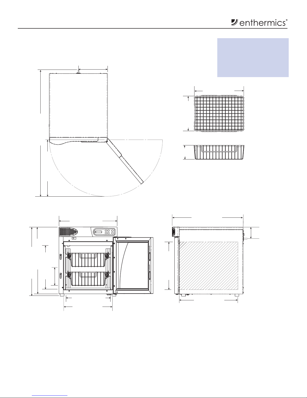
16 MN-39216 • Rev 3 • 12/18 • DC Series Fluid Warmer
Dimension Drawings
DC250L with standard feet
Clearance requirements:
4" (102mm) from rear
1" (25mm) from top
2" (51mm) from sides
1/2" (13mm) from bottom
15.1" (385mm)
CAVITY
4.5"
(113mm)
11" (280mm)
15.7" (399mm)
9.3" (235mm)
IEC Cord Inlet
CORD LENGTH
6' (1.83m) (est.)
23" (584mm)
3.6" (92mm)
IEC Cord Inlet
18.6" (472mm)
CAVITY
18.5" (470mm)
22" (559mm)
14.5" (367mm)
INSERT
15.5" (394mm)
CAVITY
18.0" (457mm)
41.1" (1044mm)
21.2" (538mm)
13.5" (342mm)
INSERT
5.5" (140mm)
USUABLE HEIGHT
NOTE: Optional 3" (76mm) casters increases the overall height by 4.3" (109mm)
17
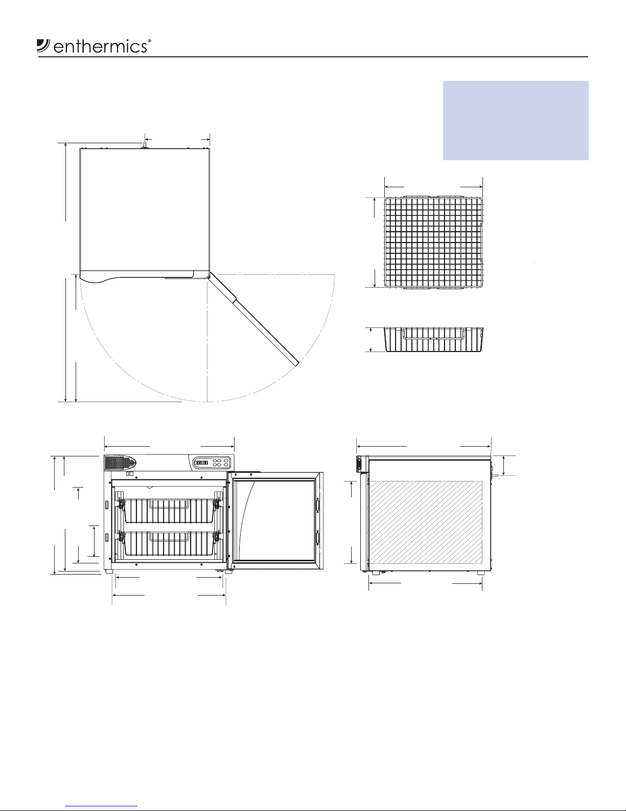
MN-39216 • Rev 3 • 12/18 • DC Series Fluid Warmer
Dimension Drawings
DC400L with standard feet
Clearance requirements:
4" (102mm) from rear
1" (25mm) from top
2" (51mm) from sides
1/2" (13mm) from bottom
4.5"
(113mm)
16.5" (420mm)
18.1" (459mm)
12.0" (305mm)
IEC Cord Inlet
CORD LENGTH
6' (1.83m) (est.)
3.6" (92mm
)
IEC Cord Inlet
20.9" (531mm)
CAVITY
25.25" (641mm)
20.0" (508mm)
INSERT
21.0" (533mm)
CAVITY
23.4" (595mm)
15.1" (385mm)
CAVITY
24.0" (610mm)
48.8" (1240mm)
22" (559mm)
21.2" (538mm)
13.5" (342mm)
INSERT
5.5" (140mm)
USUABLE HEIGHT
NOTE: Optional 3" (76mm) casters increases the overall height by 4.3" (109mm)
18 MN-39216 • Rev 3 • 12/18 • DC Series Fluid Warmer
Troubleshooting
NOTE:
If the warmer is not operating properly, check the
following before calling an authorized service agent:
• Verify that the power to the warmer is on.
• Ensure the female end of plug is securely seated in
the warmer and that the male end of plug is in an
appropriate, functioning outlet.
• Examine the fuses. Replace the fuses using the
instructions How to Replace the Fuse on page 20.
NOTE: All non-critical codes can be cleared using the ON/OFF
button. Critical errors (marked with a *) can only be
cleared by pressing the circuit breaker at the rear of the
warmer to the off (O) position and allowing the warmer
to cool.
Notice: Do not attempt to repair or service the warmer
beyond this point. Contact the manufacturer for the
nearest authorized service agent. Repairs made by
any other service agent without prior authorization by
the manufacturer will void the warranty.
This section is provided for the assistance
of qualified and trained service
technicians only and is not intended
for use by untrained or unauthorized
service personnel. Failure to observe this
precaution may void the warranty.
Troubleshooting Guide
Code Refers to Action Required
Display
flashes
set point
Cavity temperature
higher than set
point
Cavity temperature is higher than the set point temperature.
• Allow cavity to cool to set point temperature.
E-10
ES10
ES20
ES30
ES40
ES50
ES60
ES70
Cavity sensor
Sensor 1
Sensor 2
Sensor 3
Sensor 4
Sensor 5
Sensor 6
Sensor 7
Sensor is shorted. Soware disengages heating pads. Acknowledge error by pressing the
ON/OFF button. If error persists, a qualied service technician should test the sensor.
• Test the sensor. Detach the sensor from the warmer. Use an Ohm meter to measure
the resistance of the sensor. Check the sensor at 25°C (77°F). If the reading is 10 KOhm
±1.5 KOhm, replace the display. If the reading is ±2 KOhm, replace the sensor.
• Check the wires for integrity. Inspect the connections at the control and terminal
block to ensure proper and secure connections. If necessary, re-secure the faulty
connections.
• Call service if error persists.
E-11
ES11
ES21
ES31
ES41
ES51
ES61
ES71
Cavity sensor
Pad sensor 1
Pad sensor 2
Pad sensor 3
Pad sensor 4
Pad sensor 5
Pad sensor 6
Pad sensor 7
Sensor is open. Soware disengages heating pads. Acknowledge error by pressing the
ON/OFF button. If error persists, a qualied service technician should test the sensor.
• Test the sensor. Detach the sensor from warmer. Use an Ohm meter to measure the
resistance of the sensor. Check the sensor at 25°C (77°F). If the reading is 10 KOhm ±1.5
KOhm, replace the display. If the reading is ±2 KOhm, replace sensor.
• Check the wires for integrity. Check for proper and secure connections at the control
and terminal block. If necessary, re-secure the faulty connections.
• Call service if error persists.
*E-31 Cavity sensor • The sensor reading is above the temperature set-point. [Blanket warmer triggers at 15°
over set-point. Fluid warmer triggers at 5° over set-point.]
• The dierence between the room temperature and the uid set-point temperature
must be greater than 11°C (20°F).
• Call service.
P131
P231
P331
P431
P531
P631
P731
Pad sensor 1
Pad sensor 2
Pad sensor 3
Pad sensor 4
Pad sensor 5
Pad sensor 6
Pad sensor 7
Heater pad over-temp error
• Soware disengages heating pads.
• Acknowledge error by pressing the ON/OFF button.
• Allow the warmer to cool.
• Call service if the error persists.
*E-33 Cavity sensor • Sensor reading is above maximum allowable temperature set-point and over temp
value. [Blanket warmers trigger at 82°C (180°F). Fluid warmers trigger at 71°C (160°F).]
• Contact service
*E-50 Analog to Digital
Convertor Error
• Remove inventory, discard if necessary, and allow the warmer to cool down.
• If error persists aer cool down and reset, the control assembly should be replaced by
a qualied service technician. Contact service.
E-60 Real Time Clock
Checksum Error
(Blanket warmers only)
Real time clock rechargeable battery backup has discharged.
• Plug the warmer into the outlet for 30 minutes.
• See Timer Control Feature section in the blanket manual to reset the clock.
*E-61 Real Time Clock
(Blanket warmers only)
Real time clock not responding. Call service if error persists.
E-62 Real Time Clock
(Blanket warmers only)
Timer overlay is present, but no real time clock is detected. Call service.
*E-70 Pad Count Error More heater pads detected than set for. Hold the ON/OFF button for 12 seconds until
display shows "PAd#” (# = number of pads selected [3-7]). Press up or down arrow to
adjust to correct number of pads. [Blanket warmers: 1.53, 2.53= 3 pads, 3.53, 4.03, 7.53= 4
pads.
Fluid warmers: 2.53& 4.03= 3 pads]
*E-71 Personality Error Call service
E-80 EEPROM Error EEPROM not responding. Call service if error persists.
*E-81 Calibration
not locked
Call service
*E-83 EEPROM Error Call service for help resetting the control.
E-87 EEPROM Error Stored osets corrupted. Osets reset to 0.
• Control may need to be recalibrated.
• Possible bad EEPROM.
• Call service if error persists.
E-90 Button stuck A button has been held down for >60 seconds. Adjust control. Error will reset when the
problem has been resolved.
E-95 Factory Test pin
short detected.
Ensure that debris is not causing a short between the test pins. If the pins are clean,
replace the control.
*E-98 Temperature
Delta Error
Temperature of the cavity sensors 1 and 2 dier by more than 1.7ºC (3ºF).
• Remove product and allow the warmer to cool down.
• Verify that the product sensor is clean and operating correctly.
• Press the power button to clear error code.
• If error persists, the sensor switch assembly should be replaced by a qualied service
technician. Contact service.
E-99 Hardware
Over Temp
• Inspect the connections and condition of high limit bimetal thermostat.
• If error continues call service.
*EFAn Fan or Fan
Sensor Failure
(Fluid warmers only)
• Check to make sure the fan sensor wires did not disconnect from the fan or the control
board.
• If the error persists aer checking the wires, replace the fan.
* All non-critical codes can be cleared using the ON/OFF button. Critical errors (marked with a *) can only be cleared by pressing the circuit breaker at
the rear of the warmer o and allowing the warmer to cool.

19
MN-39216 • Rev 3 • 12/18 • DC Series Fluid Warmer
Troubleshooting
Troubleshooting Guide
Code Refers to Action Required
Display
flashes
set point
Cavity temperature
higher than set
point
Cavity temperature is higher than the set point temperature.
• Allow cavity to cool to set point temperature.
E-10
ES10
ES20
ES30
ES40
ES50
ES60
ES70
Cavity sensor
Sensor 1
Sensor 2
Sensor 3
Sensor 4
Sensor 5
Sensor 6
Sensor 7
Sensor is shorted. Soware disengages heating pads. Acknowledge error by pressing the
ON/OFF button. If error persists, a qualied service technician should test the sensor.
• Test the sensor. Detach the sensor from the warmer. Use an Ohm meter to measure
the resistance of the sensor. Check the sensor at 25°C (77°F). If the reading is 10 KOhm
±1.5 KOhm, replace the display. If the reading is ±2 KOhm, replace the sensor.
• Check the wires for integrity. Inspect the connections at the control and terminal
block to ensure proper and secure connections. If necessary, re-secure the faulty
connections.
• Call service if error persists.
E-11
ES11
ES21
ES31
ES41
ES51
ES61
ES71
Cavity sensor
Pad sensor 1
Pad sensor 2
Pad sensor 3
Pad sensor 4
Pad sensor 5
Pad sensor 6
Pad sensor 7
Sensor is open. Soware disengages heating pads. Acknowledge error by pressing the
ON/OFF button. If error persists, a qualied service technician should test the sensor.
• Test the sensor. Detach the sensor from warmer. Use an Ohm meter to measure the
resistance of the sensor. Check the sensor at 25°C (77°F). If the reading is 10 KOhm ±1.5
KOhm, replace the display. If the reading is ±2 KOhm, replace sensor.
• Check the wires for integrity. Check for proper and secure connections at the control
and terminal block. If necessary, re-secure the faulty connections.
• Call service if error persists.
*E-31 Cavity sensor • The sensor reading is above the temperature set-point. [Blanket warmer triggers at 15°
over set-point. Fluid warmer triggers at 5° over set-point.]
• The dierence between the room temperature and the uid set-point temperature
must be greater than 11°C (20°F).
• Call service.
P131
P231
P331
P431
P531
P631
P731
Pad sensor 1
Pad sensor 2
Pad sensor 3
Pad sensor 4
Pad sensor 5
Pad sensor 6
Pad sensor 7
Heater pad over-temp error
• Soware disengages heating pads.
• Acknowledge error by pressing the ON/OFF button.
• Allow the warmer to cool.
• Call service if the error persists.
*E-33 Cavity sensor • Sensor reading is above maximum allowable temperature set-point and over temp
value. [Blanket warmers trigger at 82°C (180°F). Fluid warmers trigger at 71°C (160°F).]
• Contact service
*E-50 Analog to Digital
Convertor Error
• Remove inventory, discard if necessary, and allow the warmer to cool down.
• If error persists aer cool down and reset, the control assembly should be replaced by
a qualied service technician. Contact service.
E-60 Real Time Clock
Checksum Error
(Blanket warmers only)
Real time clock rechargeable battery backup has discharged.
• Plug the warmer into the outlet for 30 minutes.
• See Timer Control Feature section in the blanket manual to reset the clock.
*E-61 Real Time Clock
(Blanket warmers only)
Real time clock not responding. Call service if error persists.
E-62 Real Time Clock
(Blanket warmers only)
Timer overlay is present, but no real time clock is detected. Call service.
*E-70 Pad Count Error More heater pads detected than set for. Hold the ON/OFF button for 12 seconds until
display shows "PAd#” (# = number of pads selected [3-7]). Press up or down arrow to
adjust to correct number of pads. [Blanket warmers: 1.5
3
, 2.5
3
= 3 pads, 3.5
3
, 4.0
3,
7.5
3
= 4
pads.
Fluid warmers: 2.5
3
& 4.0
3
= 3 pads]
*E-71 Personality Error Call service
E-80 EEPROM Error EEPROM not responding. Call service if error persists.
*E-81 Calibration
not locked
Call service
*E-83 EEPROM Error Call service for help resetting the control.
E-87 EEPROM Error Stored osets corrupted. Osets reset to 0.
• Control may need to be recalibrated.
• Possible bad EEPROM.
• Call service if error persists.
E-90 Button stuck A button has been held down for >60 seconds. Adjust control. Error will reset when the
problem has been resolved.
E-95 Factory Test pin
short detected.
Ensure that debris is not causing a short between the test pins. If the pins are clean,
replace the control.
*E-98 Temperature
Delta Error
Temperature of the cavity sensors 1 and 2 dier by more than 1.7ºC (3ºF).
• Remove product and allow the warmer to cool down.
• Verify that the product sensor is clean and operating correctly.
• Press the power button to clear error code.
• If error persists, the sensor switch assembly should be replaced by a qualied service
technician. Contact service.
E-99 Hardware
Over Temp
• Inspect the connections and condition of high limit bimetal thermostat.
• If error continues call service.
*EFAn Fan or Fan
Sensor Failure
(Fluid warmers only)
• Check to make sure the fan sensor wires did not disconnect from the fan or the control
board.
• If the error persists aer checking the wires, replace the fan.
Troubleshooting Guide
Code Refers to Action Required
Display
flashes
set point
Cavity temperature
higher than set
point
Cavity temperature is higher than the set point temperature.
• Allow cavity to cool to set point temperature.
E-10
ES10
ES20
ES30
ES40
ES50
ES60
ES70
Cavity sensor
Sensor 1
Sensor 2
Sensor 3
Sensor 4
Sensor 5
Sensor 6
Sensor 7
Sensor is shorted. Soware disengages heating pads. Acknowledge error by pressing the
ON/OFF button. If error persists, a qualied service technician should test the sensor.
• Test the sensor. Detach the sensor from the warmer. Use an Ohm meter to measure
the resistance of the sensor. Check the sensor at 25°C (77°F). If the reading is 10 KOhm
±1.5 KOhm, replace the display. If the reading is ±2 KOhm, replace the sensor.
• Check the wires for integrity. Inspect the connections at the control and terminal
block to ensure proper and secure connections. If necessary, re-secure the faulty
connections.
• Call service if error persists.
E-11
ES11
ES21
ES31
ES41
ES51
ES61
ES71
Cavity sensor
Pad sensor 1
Pad sensor 2
Pad sensor 3
Pad sensor 4
Pad sensor 5
Pad sensor 6
Pad sensor 7
Sensor is open. Soware disengages heating pads. Acknowledge error by pressing the
ON/OFF button. If error persists, a qualied service technician should test the sensor.
• Test the sensor. Detach the sensor from warmer. Use an Ohm meter to measure the
resistance of the sensor. Check the sensor at 25°C (77°F). If the reading is 10 KOhm ±1.5
KOhm, replace the display. If the reading is ±2 KOhm, replace sensor.
• Check the wires for integrity. Check for proper and secure connections at the control
and terminal block. If necessary, re-secure the faulty connections.
• Call service if error persists.
*E-31 Cavity sensor • The sensor reading is above the temperature set-point. [Blanket warmer triggers at 15°
over set-point. Fluid warmer triggers at 5° over set-point.]
• The dierence between the room temperature and the uid set-point temperature
must be greater than 11°C (20°F).
• Call service.
P131
P231
P331
P431
P531
P631
P731
Pad sensor 1
Pad sensor 2
Pad sensor 3
Pad sensor 4
Pad sensor 5
Pad sensor 6
Pad sensor 7
Heater pad over-temp error
• Soware disengages heating pads.
• Acknowledge error by pressing the ON/OFF button.
• Allow the warmer to cool.
• Call service if the error persists.
*E-33 Cavity sensor • Sensor reading is above maximum allowable temperature set-point and over temp
value. [Blanket warmers trigger at 82°C (180°F). Fluid warmers trigger at 71°C (160°F).]
• Contact service
*E-50 Analog to Digital
Convertor Error
• Remove inventory, discard if necessary, and allow the warmer to cool down.
• If error persists aer cool down and reset, the control assembly should be replaced by
a qualied service technician. Contact service.
E-60 Real Time Clock
Checksum Error
(Blanket warmers only)
Real time clock rechargeable battery backup has discharged.
• Plug the warmer into the outlet for 30 minutes.
• See Timer Control Feature section in the blanket manual to reset the clock.
*E-61 Real Time Clock
(Blanket warmers only)
Real time clock not responding. Call service if error persists.
E-62 Real Time Clock
(Blanket warmers only)
Timer overlay is present, but no real time clock is detected. Call service.
*E-70 Pad Count Error More heater pads detected than set for. Hold the ON/OFF button for 12 seconds until
display shows "PAd#” (# = number of pads selected [3-7]). Press up or down arrow to
adjust to correct number of pads. [Blanket warmers: 1.53, 2.53= 3 pads, 3.53, 4.03, 7.53= 4
pads.
Fluid warmers: 2.53& 4.03= 3 pads]
*E-71 Personality Error Call service
E-80 EEPROM Error EEPROM not responding. Call service if error persists.
*E-81 Calibration
not locked
Call service
*E-83 EEPROM Error Call service for help resetting the control.
E-87 EEPROM Error Stored osets corrupted. Osets reset to 0.
• Control may need to be recalibrated.
• Possible bad EEPROM.
• Call service if error persists.
E-90 Button stuck A button has been held down for >60 seconds. Adjust control. Error will reset when the
problem has been resolved.
E-95 Factory Test pin
short detected.
Ensure that debris is not causing a short between the test pins. If the pins are clean,
replace the control.
*E-98 Temperature
Delta Error
Temperature of the cavity sensors 1 and 2 dier by more than 1.7ºC (3ºF).
• Remove product and allow the warmer to cool down.
• Verify that the product sensor is clean and operating correctly.
• Press the power button to clear error code.
• If error persists, the sensor switch assembly should be replaced by a qualied service
technician. Contact service.
E-99 Hardware
Over Temp
• Inspect the connections and condition of high limit bimetal thermostat.
• If error continues call service.
*EFAn Fan or Fan
Sensor Failure
(Fluid warmers only)
• Check to make sure the fan sensor wires did not disconnect from the fan or the control
board.
• If the error persists aer checking the wires, replace the fan.
* All non-critical codes can be cleared using the ON/OFF button. Critical errors (marked with a *) can only be cleared by pressing the circuit breaker at
the rear of the warmer o and allowing the warmer to cool.
20 MN-39216 • Rev 3 • 12/18 • DC Series Fluid Warmer
Service
Part numbers and drawings are subject to change without notice.
FU-34955
F2 fuse
FU-34955
F1 fuse
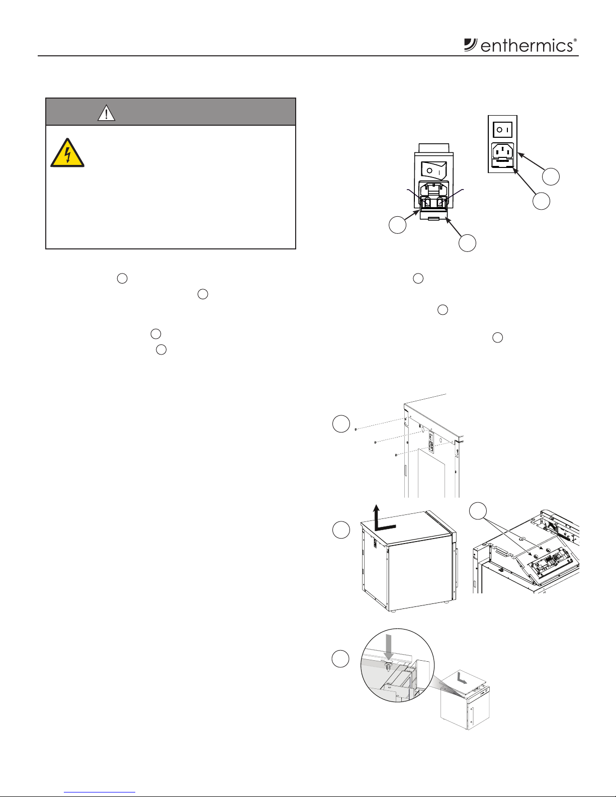
How to Replace the Fuse
1
2
3
WARNING
For protection against fire and electrical shock
use only UL listed 10A, 250V fast acting fuses,
5mm x 20mm (F1, F2). Access should be made
by qualified service technicians only.
A hospital grade cord must be used. Refer to the
owner’s manual or contact the manufacturer
for acceptable cords. The warmer must be
connected to an equivalent receptacle marked
“hospital grade”.
1. Unplug the power cord from the wall outlet and the
power inlet 1on the warmer.
2. Locate the fuse compartment 2directly below the
power inlet.
3. Use a ngernail or thin implement to open the fuse
compartment door 3.
4. Pull the fuse drawer 4out of the fuse compartment.
5.
Use a thin implement to push the fuses up and out of
the fuse drawer 4.
6. Replace the fuse with a new fuse.
7. Push the fuse drawer 4back into the fuse
compartment.
8. Close the fuse compartment door 3.
4
How to Manually Reset the Warmer
1. Disconnect the electrical power source to the uid
warmer.
2. Allow the uid warmer to cool.
3. Remove three (3) screws from the top cover (on the
upper edge of the back of the uid warmer).
4. Slide the top panel toward the back of the uid
warmer and then li to remove.
5. Locate the two (2) manual reset buttons in the
middle of the bonnet.
6. Use a pen, screwdriver or other long, thin
implement to rmly push the reset button(s). The
button clicks when it resets.
7. Place the cover on top of the warmer ensuring that
the slots on the underside of the cover line up with
the bolts on the top of the warmer. Slide the cover
toward the front of the warmer to lock into place.
8. Replace the three (3) screws at the back of the
warmer.
If the reset button trips again while the warmer is
operating, contact a qualied service technician.
3
4
5
7
Other manuals for DC250L
1
This manual suits for next models
1
Table of contents
Other Enthermics Medical Equipment manuals


Popular Medical Equipment manuals by other brands


Care Fusion
Care Fusion IVAC PCAM Directions for use

Hanatech
Hanatech MULTISCAN plus user manual

ARJO HUNTLEIGH
ARJO HUNTLEIGH Flowtron Excel Instructions for use

C-Aire
C-Aire HELiOS PLUS H300-50 Home use guide

Bionet
Bionet Oxy9Wave Vet Operation manual

ARJO HUNTLEIGH
ARJO HUNTLEIGH citadel Instructions for use


