Entron MTR50 User manual
User Manual
MTR50
1.03
February 23
Document no. 230224-1
Firmware Version
2 | P a g e
Copyright © 2021 BF ENTRON and/or its affiliates. All rights reserved
Product Model: MTR50
February 23 | Doc No. 230224-1
DISCLAIMER
Information contained in this document is believed to be accurate and reliable. The manufacturer does not provide any
representations or warranties, expressed or implied, as to the accuracy or completeness of such information and shall
have no liability for the consequences of use of such information. The manufacturer reserves the right to make changes
to information published in this document, including without limitation specifications and product descriptions, at any
time and without notice.
BF ENTRON accepts no liability for any injury, loss or damage caused by improper installation, use or application of its
products. The user shall only use the product for purposes that are proper and in accordance with all applicable laws,
rules, and regulations.
Copyright © 2022 by [BF ENTRON, Ltd.]
All rights reserved. No part of this publication may be reproduced, distributed, or transmitted in any form or by any
means, including photocopying, recording, or other electronic or mechanical methods, without the prior written
permission of the publisher.
TRADEMARKS
BR ENTRON and/or its affiliates’ trademarks may not be used in connection with any product or service that is not BF
ENTRON’s, in any manner this is likely to cause confusion among customers or in any manner that disparages or
discredits BF ENTRON. All other trademarks not owned by BF ENTRON are the property of their respective owners, who
may or may not be affiliated with, connected to, or sponsored by BF ENTRON.

3 | P a g e
Copyright © 2021 BF ENTRON and/or its affiliates. All rights reserved
Product Model: MTR50
February 23 | Doc No. 230224-1
Document Revisions
Languages
This document is only published in the English language.
Date
Document
Number
Approved By
Document Changes
24/02/2023
230224-1
Thomas
Warrington
Layout Update, Electrical Drawings added, new
pictures of product

4 | P a g e
Copyright © 2021 BF ENTRON and/or its affiliates. All rights reserved
Product Model: MTR50
February 23 | Doc No. 230224-1
Table of Contents
1Introduction ..................................................................................................................................................... 5
2Specifications ................................................................................................................................................... 6
3Connections...................................................................................................................................................... 7
3.1 Power Connection Location ....................................................................................................................... 8
3.2 Water Connection Location ....................................................................................................................... 9
4Configuring the timer..................................................................................................................................... 10
4.1 Configuration Parameters ....................................................................................................................... 10
4.1.1 Config Type .........................................................................................................................................................10
4.1.2 Input Allocations.................................................................................................................................................11
4.1.3 Output Allocations..............................................................................................................................................11
4.2 Retract ..................................................................................................................................................... 12
4.2.1 Frequency ...........................................................................................................................................................12
4.2.2 Heat Range .........................................................................................................................................................12
4.2.3 Interlock..............................................................................................................................................................12
5Welding with the MTR50 ............................................................................................................................... 14
5.1 Selecting a Weld Program ....................................................................................................................... 14
5.1.1 Using timer keypad.............................................................................................................................................14
5.2 Starting a Weld........................................................................................................................................ 15
5.3 2nd stage input........................................................................................................................................ 15
6Programming the weld programmes............................................................................................................. 16
6.1 Program parameters ............................................................................................................................... 17
7End of Sequence Output ................................................................................................................................ 18
8Counter........................................................................................................................................................... 19
8.1 Counter Parameters................................................................................................................................. 19
9Electrical Drawings......................................................................................................................................... 20
9.1 3U3742..................................................................................................................................................... 20
9.2 3U3744..................................................................................................................................................... 21
10 Technical Support........................................................................................................................................... 22
10.1.1 Internet...............................................................................................................................................................22
10.1.2 Documentation Request.....................................................................................................................................22
10.1.3 Service and Technical Support............................................................................................................................22

Introduction
5 | P a g e
Copyright © 2021 BF ENTRON and/or its affiliates. All rights reserved
Product Model: MTR50
February 23 | Doc No. 230224-1
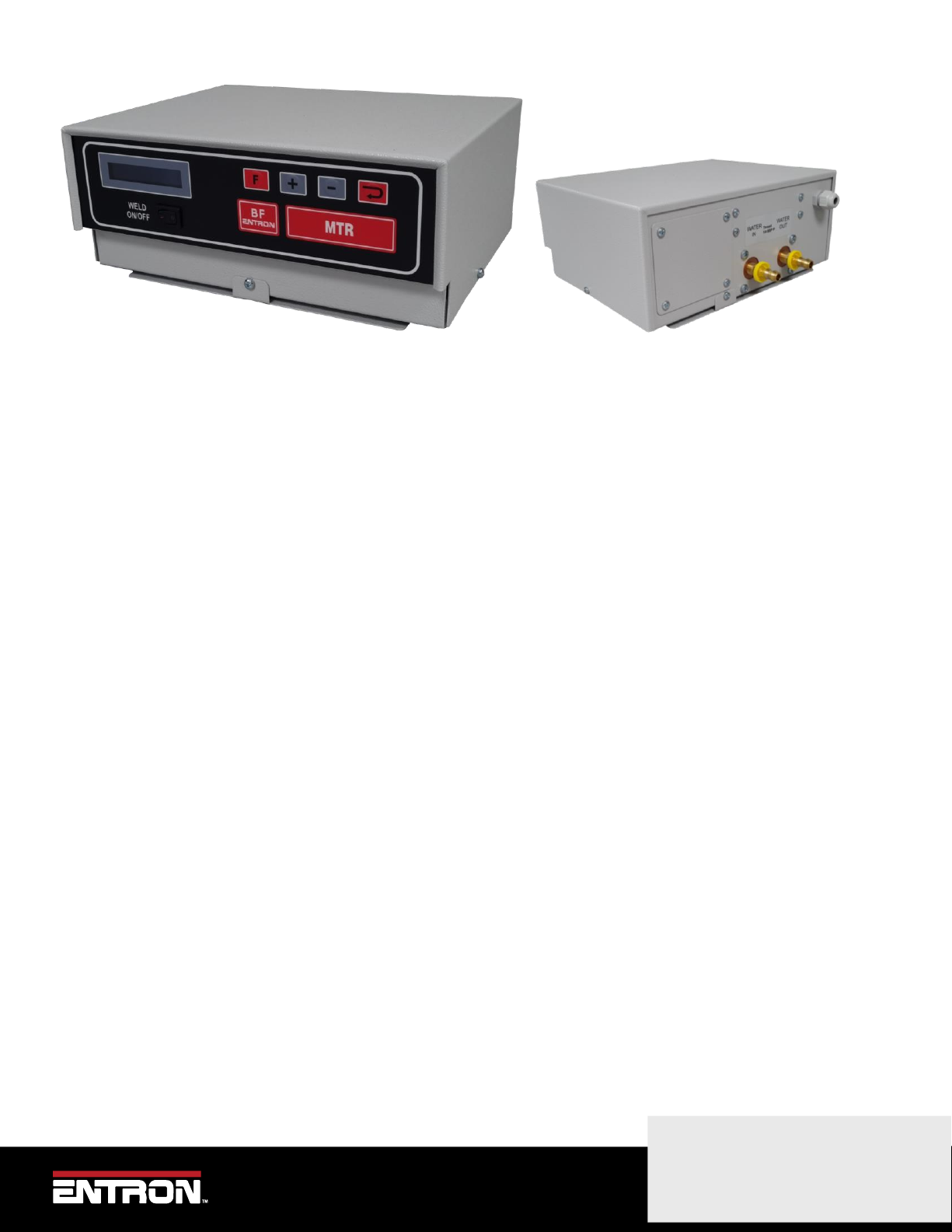
1Introduction
The MTR50 welding control offers the reliability that ensues from simplicity. The MTR50 is a compact, robust unit
providing basic control for resistance welding. The membrane front panel provides a neat, water-resistant finish and
incorporates four push buttons and a display for programming purposes. Programming is quick and simple, as is
operation of the control.
The principle features of the MTR50 are:
•50 Hz or 60 Hz operation
•2 inputs and 2 outputs plus weld on/off
•8 programmes
•Single or Repeat spot operation
•Two weld intervals and pulsation
•External program select option
•2-stage initiation option
•Retract/High lift option
•Counter option

Specifications
6 | P a g e
Copyright © 2021 BF ENTRON and/or its affiliates. All rights reserved
Product Model: MTR50
February 23 | Doc No. 230224-1
2Specifications
Mains voltage: 240V (Part Number 10-60-10-18-00)
380V,415V,440V,480V,500V*(Range determined at manufacture) (Part Number 10-60-10-18-01)
Mains frequency: 50 or 60 Hz
Duty: 20% Max.
Load: 50kVA Max.
Number of digital inputs: 2
Input requirement: 24 V DC, < 10mA
Number of digital outputs: 2
Digital output rating: 24 V DC, < 500mA
Connections
7 | P a g e
Copyright © 2021 BF ENTRON and/or its affiliates. All rights reserved
Product Model: MTR50
February 23 | Doc No. 230224-1
3Connections

Connections
8 | P a g e
Copyright © 2021 BF ENTRON and/or its affiliates. All rights reserved
Product Model: MTR50
February 23 | Doc No. 230224-1
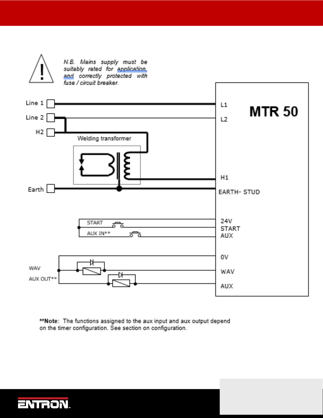
3.1 Power Connection Location
The connections for the wiring of the timer are shown graphically below.
Particular care should be taken to ensure that the wiring sizes are correct for your application and that all local
electrical regulations are adhered to.
NB. The Earth connection connects directly to the main earthing stud.
Earth
L1
L2
H2
H1
User
Connections
Connections
9 | P a g e
Copyright © 2021 BF ENTRON and/or its affiliates. All rights reserved
Product Model: MTR50
February 23 | Doc No. 230224-1
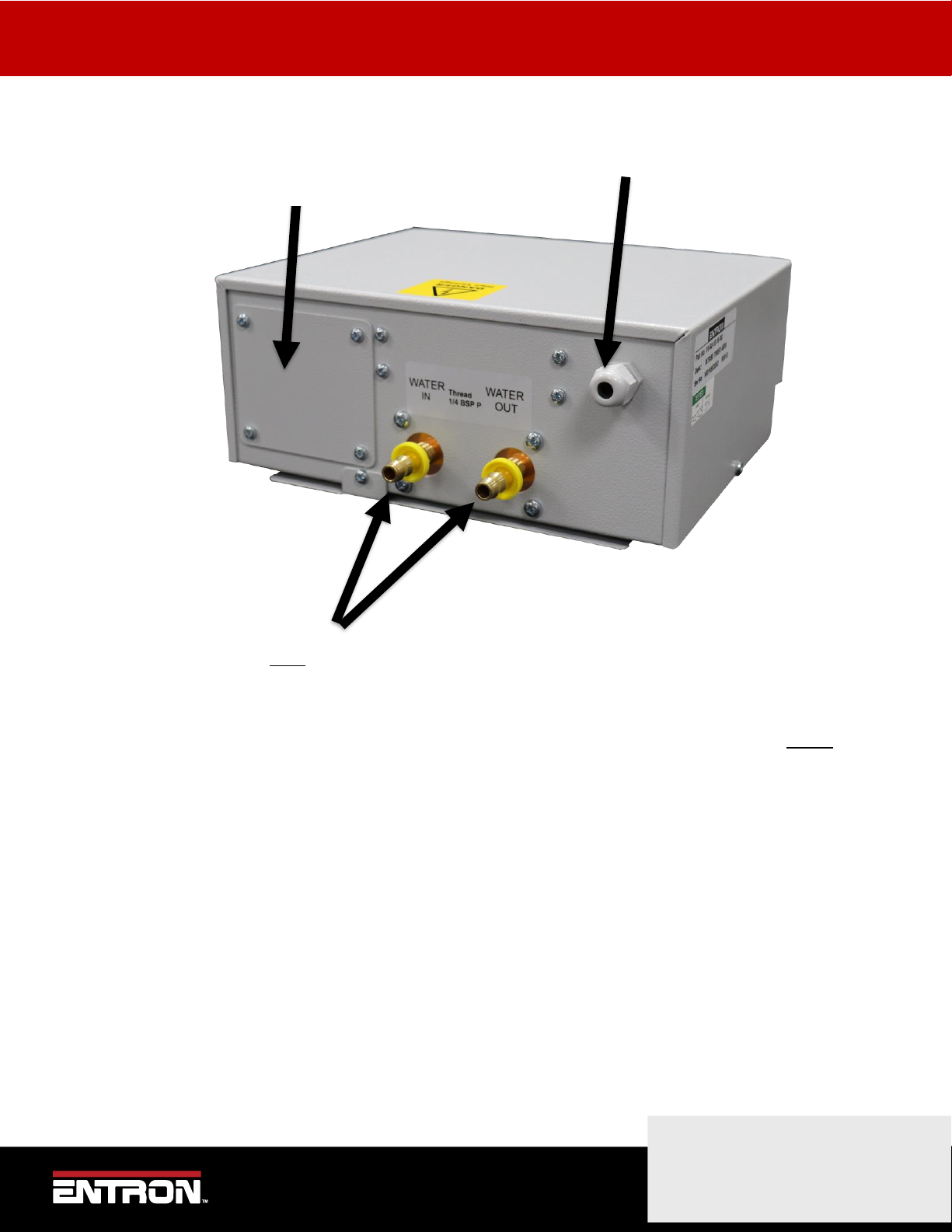
3.2 Water Connection Location
CAUTION! The MTR50 must be connected to a suitable water supply before use.
Ensure a minimum flow rate of 4.5 litres per minute, at a maximum of 40 degrees C at the inlet.
Use 3/8 inch ID pipe, secured to the hose barbs with suitable jubilee clips. Test for water leakage before
applying electrical power to the unit.
Gland for Control Cable
Gland plate for main electrical connection.
Remove this plate and fit suitable cable glands.
Configuring the timer
10 | P a g e
Copyright © 2021 BF ENTRON and/or its affiliates. All rights reserved
Product Model: MTR50
February 23 | Doc No. 230224-1
4Configuring the timer
The MTR50 has various configurations to tailor it for specific applications.
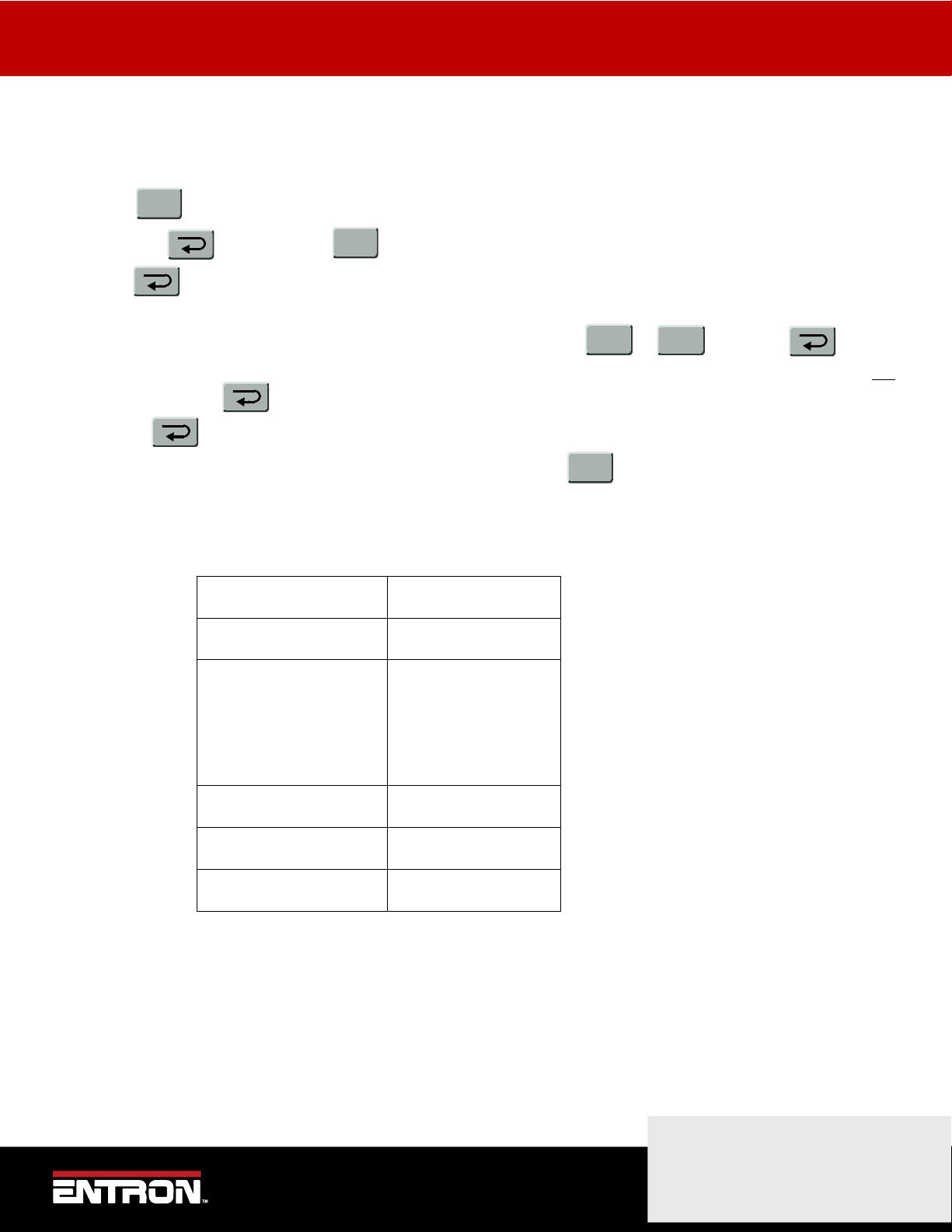
•Press until it the display reads MTR50 Vx.xx
•Hold down and then press . The display will read CONFIGURE.
•Press The display will read, for example, CONFIG TYPE 00 This is the first item in the list of
configuration parameters.
a) If you wish to change the parameter setting (in this case 00), use the or keys. Press to enter
the new value. If you do not wish to change this parameter move directly to b). Note that the new value is not
stored until the key is pressed.
b) Press to move to the next item in the configuration file.
•Repeat steps a) and b) until the configuration is complete, then press .
4.1 Configuration Parameters
The items in the list of configuration parameters is shown below.
Parameter
Options
Config type
0, 1, 2, 3
Retract
None/Simple
High Lift +
High Lift -
Frequency
50 Hz or 60 Hz
Interlock
Full / Delay / Off
Heat range
Low or High
4.1.1 Config Type
The MTR50 has 4 modes of operation, numbered as “Types” 0, 1, 2 and 3. Each Type offers different features
and may use the aux input and aux output connections in different ways. The following table gives a brief
description of what each type does.
F
F
+
-
F

Configuring the timer
11 | P a g e
Copyright © 2021 BF ENTRON and/or its affiliates. All rights reserved
Product Model: MTR50
February 23 | Doc No. 230224-1
The table should be used in conjunction with the tables of input and output allocations which show how the
inputs and outputs are used for each configuration type.
Config Type
MTR50 Operation
0
Spot welding with an input for controlling the program
number.
1
4.1.1.1 Spot welding with an external 2nd stage start input.
2
Spot welding with an input and output for controlling the
“open” and “working” positions of the welding gun (retract).
3
Spot welding with an input and output for controlling a weld
counter.
4.1.2 Input Allocations
Config Type
Start input
Aux input
0
Start
Program select
1
Start
2nd stage start
2
Start
Retract
3
Start
Counter reset
4.1.3 Output Allocations
Config Type
WAV output
Aux output
0
Weld air valve
End of sequence
1
Weld air valve
End of sequence
2
Weld air valve
Retract air valve
3
Weld air valve
Counter output
Configuring the timer
12 | P a g e
Copyright © 2021 BF ENTRON and/or its affiliates. All rights reserved
Product Model: MTR50
February 23 | Doc No. 230224-1
4.2 Retract
Configuration type 2 provides a retract facility. This feature is used when a welding gun has two “open” states: a
wide-open state for positioning the gun around a component, and a working state.
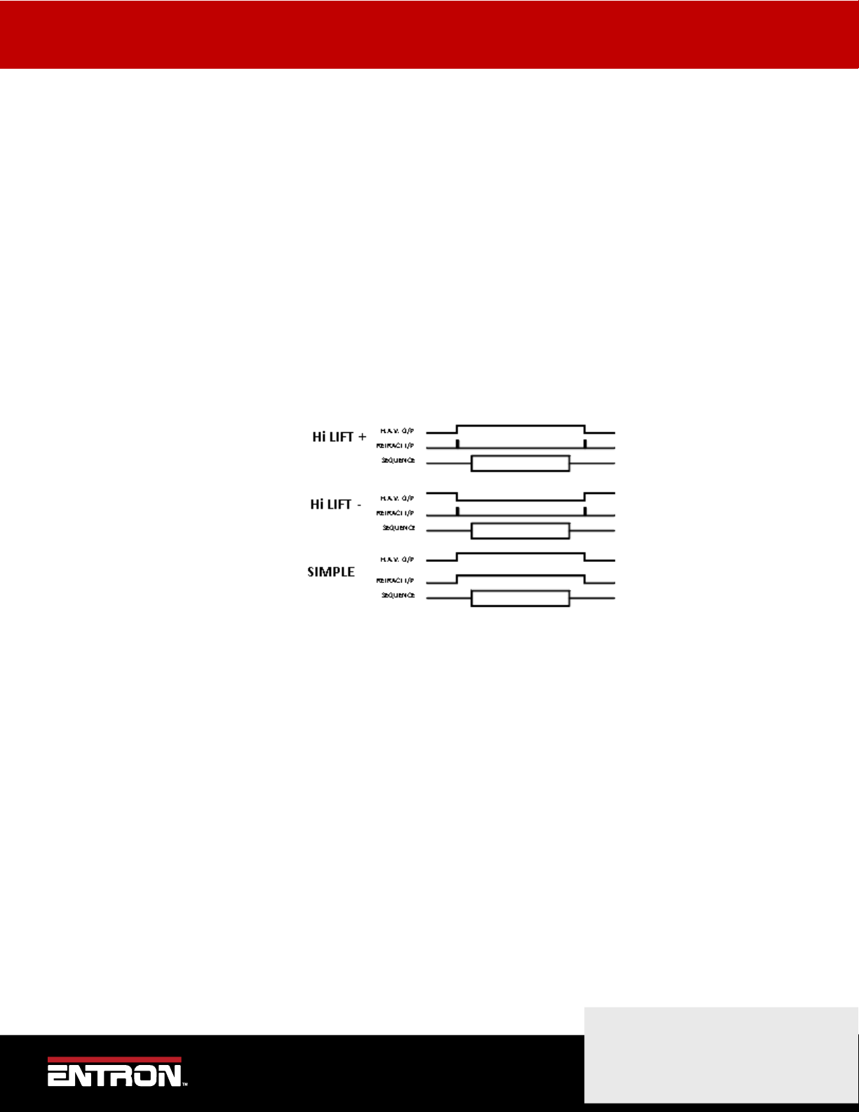
There are three modes of Retract operation:
Simple Retract The retract output directly mimics the retract input. The retract output must be off for
welding to proceed. If the retract output is on, the display will read “Retract not ready”.
Hi Lift + With this mode of retract, an impulse on the retract input changes the state of the retract
output. In this case the retract output must be on for welding to take place. If the retract
output is off, the display will read, “Retract not ready”.
Hi Lift - With this mode of retract, an impulse on the retract input changes the state of the retract
output. In this case the retract output must be off for welding to take place. If the retract
output is on, the display will read, “Retract not ready”.
4.2.1 Frequency
Select frequency of mains supply.
4.2.2 Heat Range
Select heat range High for hotter heat settings. The use of this setting may result in “dead angle” at higher heats.
(After a certain point, increasing the heat no longer increases the current).
Select heat range low for cooler heat settings. This should be used if low heat levels in the “High” setting,
produce too much current.
4.2.3 Interlock
Select Interlock OFF for machines with no weld air valve, such as pedal spot welders and poke welders. In this
mode, the weld sequence is terminated if the Start signal is removed before the sequence has completed.
Select Interlock DELAY for machines where the electrodes are controlled by the MTR50 weld air valve output. In
this mode, when a weld sequence has progressed beyond the Squeeze time, the sequence continues to
completion, regardless of the state of the Start signal.

Configuring the timer
13 | P a g e
Copyright © 2021 BF ENTRON and/or its affiliates. All rights reserved
Product Model: MTR50
February 23 | Doc No. 230224-1
Select Interlock FULL for machines operating at very high speeds or in automation systems. In this mode, when a
weld sequence has initiated, the sequence continues to completion, regardless of the state of the Start signal.
Use with caution! This mode is not available for config type 1 and will default to interlock DELAY.
WARNING! Only use the interlock FULL setting if you are absolutely sure that there is no possibility of an
operator becoming trapped by the moving parts of the welding equipment.
Welding with the MTR50
14 | P a g e
Copyright © 2021 BF ENTRON and/or its affiliates. All rights reserved
Product Model: MTR50
February 23 | Doc No. 230224-1
5Welding with the MTR50
To weld, the MTR50 needs to have been configured for your specific application. (See section on “Configuration”).
Having been configured, the timer must be programmed with the weld parameters for the job in hand. Eight sets of
weld parameters can be held in the MT50. Each set of parameters is called a “Program”.
5.1 Selecting a Weld Program
5.1.1 Using timer keypad
Press until the MTR50 displays READY.
Press . The display will show USE PROGRAM n.
Press either or to select the required program number (n), then press .
Press to return to normal mode.
Note that for configuration type 0, the timer has an external program select line. If this input is on, then this causes the
timer to add 1 to the selected program number.
e.g.
USE PROGRAM
AUX INPUT
Program to be run by
timer
3
Off
3
3
On
4
7
Off
7
7
On
0
F
+
-
F

Welding with the MTR50
15 | P a g e
Copyright © 2021 BF ENTRON and/or its affiliates. All rights reserved
Product Model: MTR50
February 23 | Doc No. 230224-1
5.2 Starting a Weld
When the timer has been configured and programmed, welding can proceed. Select the program to be used (see
previous section) and operate the Start input (input 1). A weld sequence will begin.
The Start signal must be held on until the first weld period. If the Start signal is removed before this, the weld sequence
will be aborted.
5.3 2nd stage input
Note that for configuration type 1, the timer has an external 2nd stage start input. If this input is off, then the sequence
will pause at the end of the squeeze time, and the display will show
NO 2nd STAGE
If the Start signal goes off at this point, then the sequence is aborted, and no weld is made. The sequence will not
continue until the aux input goes momentarily on.
Programming the weld programmes
16 | P a g e
Copyright © 2021 BF ENTRON and/or its affiliates. All rights reserved
Product Model: MTR50
February 23 | Doc No. 230224-1
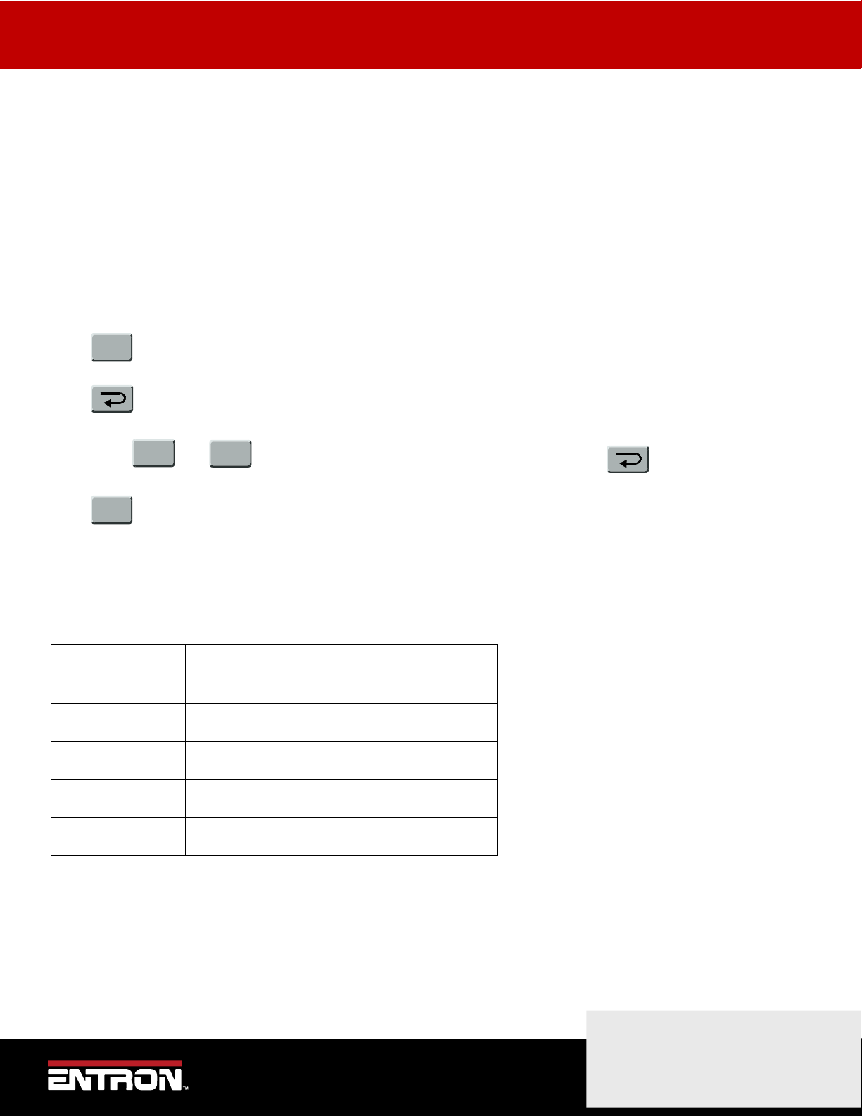
6Programming the weld programmes
Press the key until the display reads
EDIT PROGRAM 0
Use the or key to select the program required. The display will flash. Press to enter the
program number. Press again to move the programmer to the first parameter. With each parameter use the
and keys to change the value. This will cause the display to flash. When the value is correct, enter it by
pressing . Press again to move onto the next parameter. At any point can be pressed to exit
programming weld parameters.
The table below shows the welding parameters and the order in which they appear.
Parameter
Range of values
Mode
Single or Repeat
Heat 1
0 –99
Heat 2
0 –99
Presqueeze **
0 –99
Squeeze
0 –99
Weld 1
0 –99
Cool 1
0 –99
Weld 2
0 –99
Cool 2
0 –99
Pulses
1 –9
Hold
0 –99
Off **
0 –99
**NOTE: these parameters will only appear if the MODE parameter has been set to REPEAT.
F
+
-
+
-
F

Programming the weld programmes
17 | P a g e
Copyright © 2021 BF ENTRON and/or its affiliates. All rights reserved
Product Model: MTR50
February 23 | Doc No. 230224-1
6.1 Program parameters
Mode Selects either Single Sequence or Repeat Sequence operation. Single Sequence
operation performs one weld sequence when the timer is initiated. Repeat Sequence
performs successive weld sequences for the duration of the Start signal.
Heat 1 Controls the heat of the first weld interval.
Heat 2 Controls the heat of the second weld interval.
Presqueeze The time (in cycles) allowed for the electrodes to initially meet (only used for the first
spot in repeat mode).
Squeeze The time (in cycles) allowed for the electrodes to build up full welding pressure on the
component.
Weld 1 The duration (in cycles) of the first weld interval.
Cool 1 The time (in cycles) between the first and second weld intervals.
Weld 2 The duration (in cycles) of the second weld interval.
Cool 2 (Only applicable when using pulsations) The time (in cycles) between pulses of Weld 2.
Pulses The number of pulses of Weld 2.
Hold The time (in cycles) for which welding pressure is maintained on the weld after welding
current has ceased.
Off (Only applicable in Repeat mode). The time (in cycles) between successive weld
sequences.

End of Sequence Output
18 | P a g e
Copyright © 2021 BF ENTRON and/or its affiliates. All rights reserved
Product Model: MTR50
February 23 | Doc No. 230224-1
7End of Sequence Output
For configuration types 0 and 1, at the end of the weld sequence the End of Sequence output switches on. If the Start
signal is still present, the End of Sequence signal remains on until the Start signal is removed.
In Single Spot operation, at the end of the weld sequence the End of Sequence output switches on. If the Start signal is
absent, the End of Sequence signal switches on only momentarily.
In Repeat Spot operation the End of Sequence output switches on for the Off time between sequences, and
momentarily after the final sequence.
Start Signal
End of Seq. Signal
Weld Sequence
Start Signal
End of Seq. Signal
Weld Sequence
Start Signal
End of Seq.
Weld Sequence

Counter
19 | P a g e
Copyright © 2021 BF ENTRON and/or its affiliates. All rights reserved
Product Model: MTR50
February 23 | Doc No. 230224-1
8Counter
Configuration type 3 provides a counter facility. In this, an “End Count” value is programmed into the MTR50. A counter
within the MTR50 increments each time a weld sequence is completed. When the number of welds completed equals
the number of welds programmed as “End Count”, the Count Output switches on.
If “Stop at End” has been programmed, the timer will ignore Start inputs when this stage has been reached. If “Continue
at End” has been programmed, welding can continue.
The counter and the Count Output can be cleared by applying a signal to the Reset input.
At any stage the progress of the counter can be observed, and changed if required.
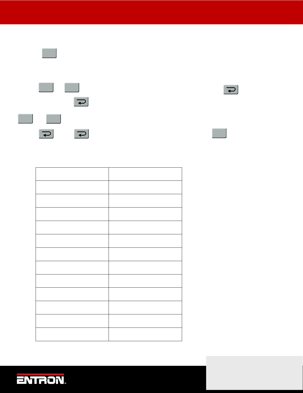
•Press until it the display reads COUNTER
•Press The display will read, for example, COUNT NOW = 0005
a) If you wish to change the parameter use the or keys. Press to enter the new value. Note that
the new value is not stored until the key is pressed.
b) Press to move to the next item in the counter file.
•Repeat steps a) and b) until the counter set-up is complete, then press .
8.1 Counter Parameters
The items in the list of counter parameters is shown below.
Parameter
Options
Count now
0 .. 9999
Count up to
0 .. 9999
Stop at end
Stop or Continue
Count now: this is the value presently counted. This can be reset to zero by applying the reset counter input, or by
entering zero from the keypad.
Count up to: this is the value which defines the end of the count. When Count now is greater than or equal to Count
up to, the counter output will turn on.
Stop/Continue at end: If Stop at end is selected, then no further welding is permitted when the end of count is
reached. If Continue at end is selected, then further welding may take place, but the counter output will remain on.
F
+
-
F
Electrical Drawings
20 | P a g e
Copyright © 2021 BF ENTRON and/or its affiliates. All rights reserved
Product Model: MTR50
February 23 | Doc No. 230224-1
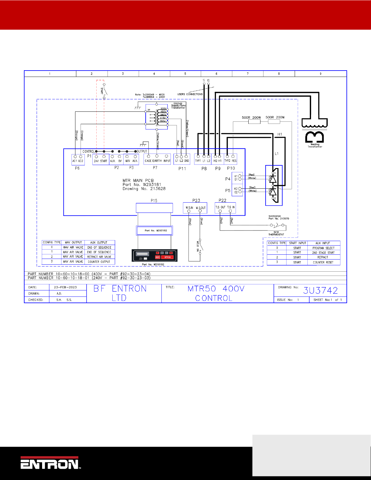
9Electrical Drawings
9.1 3U3742
Table of contents
Popular Welding System manuals by other brands

Magmaweld
Magmaweld ID 400E user manual

Amada
Amada EZ-AIR Operation manual

STAUFF
STAUFF SWG-WG operating manual

Lincoln Electric
Lincoln Electric VRTEXTM 360 SVM200-A Service manual

Miller Electric
Miller Electric SWINGER 180 Installation, operation & maintenance manual

Michigan Welding
Michigan Welding MIG135 operating instructions


Polyvance
Polyvance Nitro-Fuzer 8002 quick start guide

Lincoln Electric
Lincoln Electric MARQUETTE AutoPro 90S Operator's manual

Miller
Miller DYNASTY 700 owner's manual

WIA
WIA Weldmatic Weldarc 145i Operator's manual

Hypertherm
Hypertherm powermax1650 Operator's manual

ESAB
ESAB Migmaster 173 instruction manual