STAUFF SWG-WG User manual
Local Solutions For Individual Customers Worldwide
Operating Manual
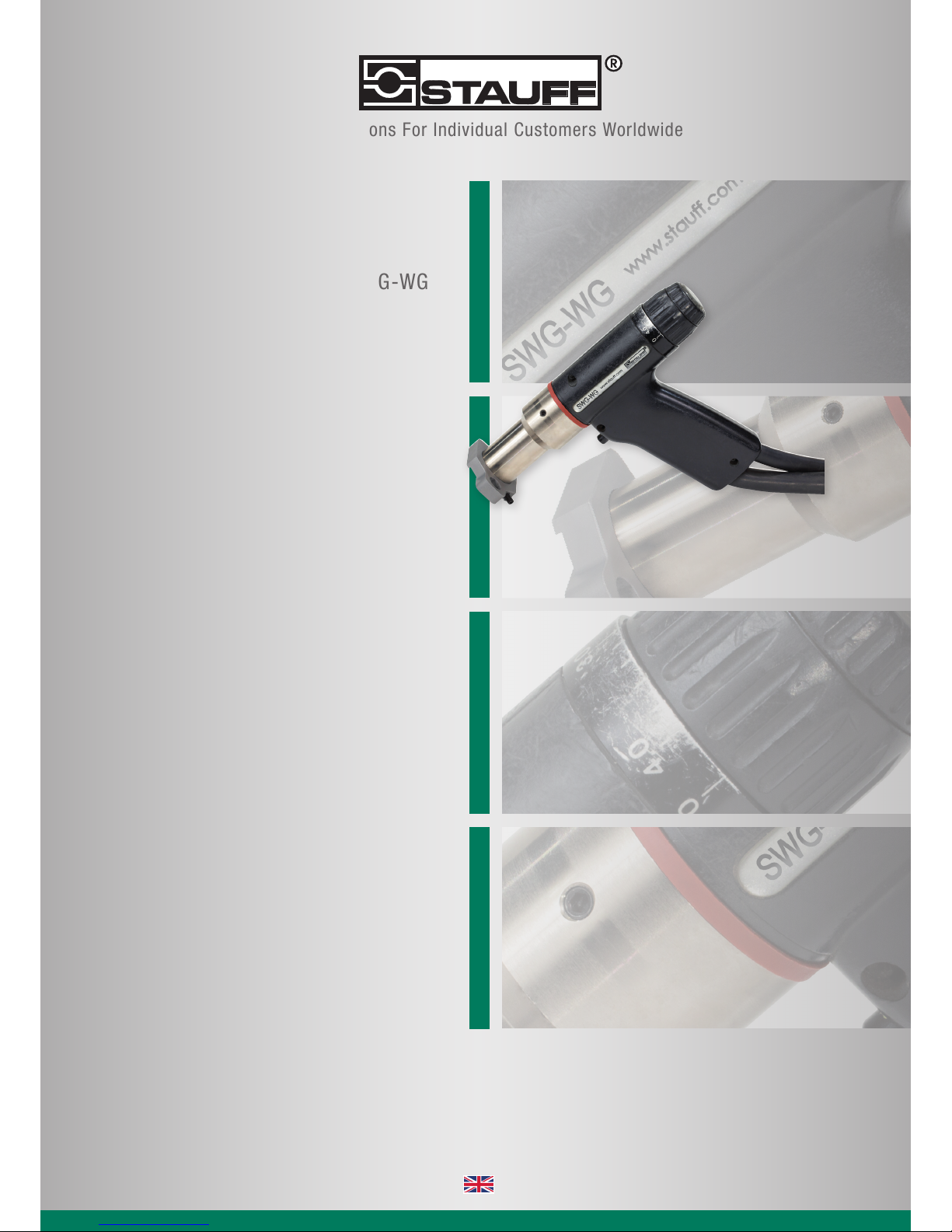
SWG-WG
SWG-WG

2
After-sales service for Germany:
Walter Stauffenberg GmbH & Co. KG
Im Ehrenfeld 4
58791 Werdohl
GERMANY
Phone. +49 (0) 23 92 / 916 - 0
Fax +49 (0) 23 92 / 25 05
E-Mail [email protected]
Web www.stauff.com
SWG-WG Operating Manual Issue 2016-06
Translation of the Original Operating Manual
Please keep the manual in a safe place for future reference.
Transmission and duplication of this document, dissemination and notication
of the contents are not permitted unless expressly approved.
All rights, errors and technical amendments reserved.
© Walter Stauffenberg GmbH & Co. KG

3
©Walter Stauffenberg GmbH & Co. KG
All rights reserved – Reprinting, in whole or in part, only with the approval of the manufacturer
Dear Customer,
Many thanks for buying a stud welding machine from STAUFF.
We at STAUFF wish you success at all times when working with this stud welding
machine.
The high level of quality of our products is guaranteed by ongoing further
development in the design, equipment and accessories. This may result in
differences between the present operating manual and your product.
No claims can therefore be derived from the data, illustrations and descriptions.
We have compiled the data and information in this reference work with the greatest
care, and have made every effort to ensure that the information contained in this
manual was correct and up-to-date at the time of delivery. We can nevertheless give
no guarantee for an absolutely error-free document.
Should you discover any errors or unclear points when reading this operating
manual, please do not hesitate to contact us.
We would also be grateful for any feedback should you have any suggestions or
complaints to make about our product.
Walter Stauffenberg GmbH & Co. KG
Im Ehrenfeld 4
58791 Werdohl
GERMANY

4
Table of Contents
©Walter Stauffenberg GmbH & Co. KG
All rights reserved – Reprinting, in whole or in part, only with the approval of the manufacturer
Table of Contents
1 Important Safety Precautions ������������������������������������������������������������������� 6
2 Symbols and Terms Used ������������������������������������������������������������������������� 9
3 Scope of Supply ��������������������������������������������������������������������������������������� 12
4 Technical Data ������������������������������������������������������������������������������������������ 13
5 Intended Use �������������������������������������������������������������������������������������������� 14
5.1 Usage with STAUFF Clamps ................................................................................ 14
6 Warranty ��������������������������������������������������������������������������������������������������� 15
6.1 Disclaimer ............................................................................................................. 15
7 Design and Function ������������������������������������������������������������������������������� 16
8 Welding Process �������������������������������������������������������������������������������������� 17
9 Preparing the Stud Welding Gun ����������������������������������������������������������� 18
9.1 Mounting the Tripod .............................................................................................. 19
9.2 Setting the Welding Parameters ........................................................................... 20
Adjusting Lift ....................................................................................................................... 22
Adjusting Spring Force ....................................................................................................... 23
10 Welding ����������������������������������������������������������������������������������������������������� 24
11 Troubleshooting ��������������������������������������������������������������������������������������� 25
12 Maintenance and Care ����������������������������������������������������������������������������� 27
12.1 Cleaning ............................................................................................................... 27
12.2 Inspection and Tests ............................................................................................. 28

5
Table of Contents
©Walter Stauffenberg GmbH & Co. KG
All rights reserved – Reprinting, in whole or in part, only with the approval of the manufacturer
13 Storage ����������������������������������������������������������������������������������������������������� 29
14 Disposal ���������������������������������������������������������������������������������������������������� 29
Declaration of Incorporation of partly completed Machinery �������������������������� 30
Service & Support ������������������������������������������������������������������������������������������������ 31
Index ���������������������������������������������������������������������������������������������������������������������� 32

6
1 Important Safety Precautions
©Walter Stauffenberg GmbH & Co. KG
All rights reserved – Reprinting, in whole or in part, only with the approval of the manufacturer
1 Important Safety Precautions
The target group for this manual are qualied personnel who in view of their technical
training, know-how and experience and knowledge of applicable regulations are
able to assess the work assigned to them and recognise potential hazards.
Danger from incorrect use
Use the stud welding machine only for the purpose described in this
manual.
Otherwise you may endanger yourself or damage the stud welding machine.
You endanger yourself and others if you operate the stud welding machine
incorrectly or fail to observe the safety precautions and warnings.
This can lead to serious injury or extensive material damage.
Danger for unauthorised operating personnel
Work with the stud welding machine only when
– You are appropriately trained, instructed and authorised to do so, and
– You have read and completely understood this operating manual.
Never work with the stud welding machine when you are under the
inuence of
– Alcohol,
– Drugs or
– Medication.
Danger from unauthorised modications
Never modify the stud welding machine or parts thereof without obtaining
a clearance certicate from the manufacturer.
You will otherwise endanger yourself. This can lead to serious injury or
extensive material damage.

7
1 Important Safety Precautions
©Walter Stauffenberg GmbH & Co. KG
All rights reserved – Reprinting, in whole or in part, only with the approval of the manufacturer
Danger for wearers of heart pacemakers
Never operate the stud welding machine if you have a heart
pacemaker.
In this case, never remain in the vicinity of the stud welding machine
during welding.
Never operate the stud welding machine if persons with heart
pacemakers are in the vicinity.
Strong electromagnetic elds are produced in the vicinity of the stud
welding machine during welding. These elds may impair the function
of the heart pacemakers.
Danger from fumes and airborne particulates
Switch on the welding fume extractor at the place of work.
Ensure that the room is well ventilated.
Never weld in rooms with a ceiling height of less than 3 m.
Observe furthermore your working instructions and the accident
prevention regulations.
This will help to avoid health damage due to fumes and airborne
particulates.
Danger from glowing metal spatter (re hazard)
Glowing hot weld spatter and liquid splashes, ashes of light and a
loud bang > 90 dB (A) must be anticipated during stud welding.
Inform colleagues working in the immediate vicinity accordingly
before starting work.
Ensure that an approved re extinguisher is available at the
workplace.
8
1 Important Safety Precautions
©Walter Stauffenberg GmbH & Co. KG
All rights reserved – Reprinting, in whole or in part, only with the approval of the manufacturer
Do not weld when wearing working clothes soiled with ammable
substances such as oil, grease, petroleum, etc.
Wear your proper protective clothing, such as:
– Protective gloves in accordance with the relevant standard,
– Non-ammable clothing,
– A protective apron over your clothing,
– Full-ear hearing protection in accordance with the relevant
standard,
– A safety helmet when welding above your head,
– Safety shoes,
– Safety goggles with sight glass of protection level 2 in compli-
ance with the applicable standards and do not look directly into
the light arc.
Remove all ammable materials and liquids from the vicinity of the
work area before starting welding.
Weld at a safe distance from ammable materials or liquids.
Select a safety distance large enough to ensure that no danger can
arise from weld spatter.
Protection of the stud welding unit
Protect the stud welding machine against the ingress of foreign
matter and liquids caused by cutting or grinding work in the vicinity
of your work area.
This will help to prolong the service life of your stud welding machine.

9
2 Symbols and Terms Used
©Walter Stauffenberg GmbH & Co. KG
All rights reserved – Reprinting, in whole or in part, only with the approval of the manufacturer
2 Symbols and Terms Used
The symbols used in this operating manual have the following meanings:
Danger
Warns you of hazards that can lead to injury of persons or to
considerable material damage.
Caution
Problems with the operating procedures can occur if this information is
not observed.
No access for people with active implanted cardiac devices
Danger
Warns you of electrical hazards
Danger
Warns you of electromagnetic elds that can be generated during welding
These symbols prompt you to wear personal protective clothing when
working with the stud welding unit.
This symbol prompts you to wear ear protection.A loud bang > 90 dB (A)
can occur during the welding process.
10
2 Symbols and Terms Used
©Walter Stauffenberg GmbH & Co. KG
All rights reserved – Reprinting, in whole or in part, only with the approval of the manufacturer
Tip
Cross-reference to useful information on the use of the stud welding
machine
Cross-references in this operating manual are marked with this
symbol or are printed in italics
Fire hazard
Have a suitable re extinguisher for the working area ready before starting
work.
Work instruction
– List

11
2 Symbols and Terms Used
©Walter Stauffenberg GmbH & Co. KG
All rights reserved – Reprinting, in whole or in part, only with the approval of the manufacturer
Glossary
Automatic welding head: Device for welding of welding elements
Capacitor: Component for storage of electrical energy.
Light arc: Independent gas discharge between two electro-
des when the current is high enough. A whitish light
is emitted in the process. The light arc allows very
high temperatures to be generated.
Rectier: Electrical component that converts alternating
voltage into direct voltage
Stud feeder: Device for automatic feeding of welding elements
Stud welding gun: Device for welding of welding elements
Stud welding machine: Stud welding unit including stud welding gun
Stud welding unit: Device for provision of the electrical energy for
stud welding
Thyristor: Electronic component for contact-free switching of
high currents; switching takes place via the control
input
Welding element: Component such as stud or pin that is welded to
the workpiece
Welding parameters: Mechanical and electrical settings at the stud
welding gun and at the stud welding unit (e.g.
spring force, charging voltage)
Workpiece: Components such as sheet metal or tubes to which
the welding elements are to be fastened

12
3 Scope of Supply
©Walter Stauffenberg GmbH & Co. KG
All rights reserved – Reprinting, in whole or in part, only with the approval of the manufacturer
3 Scope of Supply
The basic conguration of your stud welding gun contains the following parts:
No. of
pieces
Part Type
1 Stud welding gun
cable length 5 m
SWG-WG
1 Operating manual SWG-WG
1 Toolkit
optional
distance tube DIT Ø 25mm
distance tube DIT Ø 30mm
stud retainer
spacer size 1,1a,-8
Inspect the shipment for visible damage and completeness immediately
on receipt.
Report any transport damage or missing components immediately to the
delivering shipping agent or the dealer (address, see page 2).

13
4 Technical Data
©Walter Stauffenberg GmbH & Co. KG
All rights reserved – Reprinting, in whole or in part, only with the approval of the manufacturer
4 Technical Data
Stud welding gun type SWG-WG
for ARC stud welding according to current standards
Welding range M3 - M12, Ø 2 - 12 mm / 0.1 - 0.5 in
Stud length 10 - 400 mm / 0.4 - 15.7 in
(depending on tripod)
STAUFF stud 14mm / 0.6 in
Stud material Mild steel, other on request
Stud type Any type or shape (special chucks if required)
Length compensation 3 mm / 0.1 in automatic
Lift Adjustment range 3 mm / 0.1 in, lockable
Spring force Adjustable, arresting
Welding cable 5 m / 197 in
IP-Code IP 20 (protect against humidity)
Workplace noise level Up to 90 dB (A) may occur during welding
Ambient temperature limits ±0 °C bis +40 °C / ±32 °F bis +104 °F
Dimension L x W x H 200 x 65 x 140 mm / 7.9 x 2.6 x 5.5 in
(without cable, without DIT)
Weight 0,8 kg / 1.8 lbs (without cable)

14
5 Intended Use
©Walter Stauffenberg GmbH & Co. KG
All rights reserved – Reprinting, in whole or in part, only with the approval of the manufacturer
5 Intended Use
The stud welding gun has been designed exclusively for use with standardised stud
welding elements. The use of any other elements will result in the desired strength
of the welded joint being diminished.
The stud welding gun must only be connected to STAUFF stud welding units.
Always check with the operating manual of your stud welding unit whether this
stud welding gun may be used.
Observation of the operating manual of the stud welding unit being used is also part
of the intended use.
5.1 Usage with STAUFF Clamps
For obtaining the maximum power rating of the weld joint, in usage with STAUFF
Clamps, is a maximum height of the welded element of 13.0 mm observed.
In addition, the maximum torque rating of 6 Nm must be adhered in the
application.
Specic series can limit the torque additionally.
In case of doubt, please contact STAUFF.

15
6 Warranty
©Walter Stauffenberg GmbH & Co. KG
All rights reserved – Reprinting, in whole or in part, only with the approval of the manufacturer
6 Warranty
Please refer to the latest "General Terms and Conditions" for the scope of the
warranty.
The warranty does not cover faults caused by e.g.
– Normal wear,
– Improper handling,
– Failure to observe the operating manual,
– Failure to observe the safety precautions,
– Use for other than the intended purpose, or
– Transport damage.
Warranty entitlement shall no longer be valid if modications, changes or service
and repair work is carried out by unauthorised persons or without the knowledge
of the manufacturer. Invalidation of warranty entitlement shall also render the
declaration of conformity invalid. The CE marking shall be declared invalid by
the manufacturer.
We expressly point out that only spare parts and accessories or components
approved by us may be used. The same applies likewise to installed units from
our sub-suppliers.
6.1 Disclaimer
STAUFF provides SWG, devices and accessories with its production range for the
use of attaching STAUFF Clamps according to DIN3015-1.
The STAUFF production range SWG, devices and accessories uses short-term stud
welding with drawn-arc (procedure 784).
The executing welding personnel bears the responsibility for strength and quality of
welding joints.
Please note especially chapter 5.1.
Welding personnel and coordination as well as further framework conditions must
meet the requirements according to ISO 14555.
Beside the common examination agreement between the welding joint creator and
the purchaser of the product there are the simplied or the recommended production
control tests according to ISO 14555 to be executed.

16
7 Design and Function
©Walter Stauffenberg GmbH & Co. KG
All rights reserved – Reprinting, in whole or in part, only with the approval of the manufacturer
7 Design and Function
7
81
2
3
4
6
5
9
The stud welding gun SWG-WG is equipped with an integrated length adjustment
for automatic compensation of length tolerance for the welding elements.
The body of the stud welding gun consists of a sturdy two-part plastic housing (2).
The control cable and the welding cable (3) are connected through the welding
gun handle to the welding gun.
Positioned at the front of the stud welding gun are the welding piston and the
retaining nut (6) used to x the manual chuck.
At the front of the stud welding gun, the distance tube (DIT) (5) is installed.
Here the DIT is mounted.
At the rear, there is the mechanism for lift adjustment (8), rotating graduated
ring (7) and for spring force adjustment (1).
At the front of the welding gun handle, the welding gun trigger (4) is installed.
It is used to trigger the welding process.
The stud welding gun is supplied without a stud retainer (SR) (9).
The serial number is stamped on the welding gun handle.
Type plate
The type plate contains the following information:
– Manufacturer
– Type

17
8 Welding Process
©Walter Stauffenberg GmbH & Co. KG
All rights reserved – Reprinting, in whole or in part, only with the approval of the manufacturer
9 Welding Process
This stud welding gun may only be used for drawn arc stud welding.
Please refer to the original operating manual of the connected stud welding unit
for the welding procedure.

18
9 Preparing the Stud Welding Gun
©Walter Stauffenberg GmbH & Co. KG
All rights reserved – Reprinting, in whole or in part, only with the approval of the manufacturer
9 Preparing the Stud Welding Gun
Prepare the stud welding gun by
– mounting the chuck
– mounting the DIT
– adjusting lift and spring force
– adjusting the penetration depth (protrusion).
Do not connect the stud welding gun to the stud welding unit until it has
been prepared.
In this way you can avoid any unintentional starting of the welding process.

19
9 Preparing the Stud Welding Gun
©Walter Stauffenberg GmbH & Co. KG
All rights reserved – Reprinting, in whole or in part, only with the approval of the manufacturer
9.1 Mounting the chuck (SR) /
Setting the Insertion Depth (Protrusion)
chuck
Use the Allen key to remove the three screws of the
positioning tube and remove the tube
Remove the hexagon nut with the socket spanner and
remove the stud holder
Place a stud into new stud holder
Insert the stud holder loosely into the front opening
Loosely place the positioning tube
Adjust distance X by inserting the stud holder
Carefully remove the positioning tube
Tighten the hexagon nut with the socket spanner
(Ensure not to change the position of the stud holder!)
Place the positioning tube and tighten the three screws lightly
5
x
A
69
5
Allocation of adapter to xing type of clamp bodies
Size STANDARD
1AGS-1
1a AGS-1A
2AGS-2
3AGS-3
4AGS-4
5AGS-5
6AGS-6
7AGS-7
8AGS-8
* Use of the AGS only in connection with DIT-SR6-SWG-WG25R

20
9 Preparing the Stud Welding Gun
©Walter Stauffenberg GmbH & Co. KG
All rights reserved – Reprinting, in whole or in part, only with the approval of the manufacturer
9.2 Setting the Welding Parameters
The insertion depth, lift and spring force are, among others, dependent on the
workpiece and welding elements used and their diameters.
The specications in the following table are guidelines.
Select the applicable parameters for insertion depth, lift and spring force for
your workpiece.
Welding elements
Material:
4.8 (suitable for welding) / A2-50 4)
Diameter of welding elements
SWG-WG
metric imperial (US)
Stud-
diameter
in mm
eff. diameter
in mm
Stud-
diameter
in inches
eff. diameter
in inches
Stud welding gun parameter 1)
Insertion
depth Lift Spring
force
Material of workpiece: Mild steel (suitable for welding) / alloyed steel (suitable for welding) 4)
Ø d1Ø d2Ø d1Ø d2
RD (MR) 2) M6 4.7 1/4“ 0.187 2.0 1.0 6
RD (MR) 2) M8 6.2 5/16“ 0.275 2.0 1.0 6
RD (MR) 2) M10 7.9 3/8“ 0.312 2.5 1.2 6
RD (MR) 2) M12 9.5 1/2“ 0.435 3.0 1.4 6
Ø d1Ø d2Ø d1Ø d2
PD/DD (MD) 2) M6 5.35 1/4“ 0.21 2.0 1.0 6
PD/DD (MD) 2) M8 7.19 5/16“ 0.28 2.5 1.2 6
PD/DD (MD) 2) M10 9.03 3/8“ 0.35 3.0 1.4 6
PD/DD (MD) 2) M12 10.86 1/2“ 0.43 3.0 1.4 6
Ø d1Ø d1
UD / Pins 2) 3 (ISO) #4 / 12 gage 1.5 1.0 6
UD / Pins 2) 4 (ISO) #8 1.5 1.0 6
UD / Pins 2) 5 (ISO) #10 / 3/16“ 2.0 1.0 6
UD / Pins 2) 61/4“ 2.0 1.0 6
UD / Pins 2) 85/16“ 2.5 1.2 6
UD / Pins 2) 10 7/16“ 3.0 1.4 6
UD / Pins 2) 12 1/2“ 3.0 1.6 6
Ø d1Ø d2Ø d1Ø d2
IS M6 8 1/4“ 5/16“ 1.5 1.6 5
1) to be checked by test weldings
2) Information and recommendations on this can be found in DIN EN ISO 14555.
4) When welding on galvanized workpieces we recommend increasing the lift.
Ød2
Ød1
Table of contents
Other STAUFF Welding System manuals


