manuals.online logo
Brands
  1. Home
  2. •
  3. Brands
  4. •
  5. Polyvance
  6. •
  7. Welding System
  8. •
  9. Polyvance Nitro-Fuzer 8002 User manual

Polyvance Nitro-Fuzer 8002 User manual

8002 Nitro-Fuzer® Quick Start Guide
Getting started:
Page 1
1. Assemble the welding cart and mount the
8002 welder to the top shelf using 2 sheet
metal screws (included). Connect the air
manifold to the air inlet on the back of the
welder with the green tubing.
2. Unpack the accessories box. Place
the welding rod in the bins on top of the
cart and thread the welding tips into the
appropriate welder.
3. Place the nitrogen welder into the top
holster and make sure there is nothing
ammable near the hot end of welder.
Place the airless welder into the lower
holster.
4. Install your shop’s male air tting in the
bottom of the air manifold on the front of the
cart. If desired, you may install a hose to
the front of the manifold to power air tools.
5. Secure your nitrogen tank to the back of
the cart with chains (included), move the top
tank cradle as needed. Mount the regulator
to the nitrogen bottle. Connect the N2inlet
on the welder to the regulator with tubing.
6. With the welder o󰀨, connect your
CLEAN, DRY, and OIL-FREE shop air
supply to the manifold.
CAUTION: Always use CLEAN,
DRY, and OIL-FREE air for the
nitrogen welder. Water and/or
oil inside the heating element
will drastically shorten its life
span.
Congratulations on purchasing Polyvance’s 8002 nitrogen plastic welder. Prior to powering
up the welder, please read and follow the directions outlined in this booklet on the setup
and use of your plastic welder. Scan the QR code using your smartphone to watch the
Setup and Use video. Failure to read and fully understand these instructions or failure to
watch the instructional video will potentially cause damage to your welder, will increase
your risk of injury, and may cause the welder to become a re hazard. Videos are also
accessible on our website at: https://www.polyvance.com/video
2A
3
4
Your hose
Your shop
tting
5A
Chain to
cart
Adjustable
tank cradle
6
Your shop air
5B
2B
1
Setup and Use Video
Page 2
7. Adjust the nitrogen regulator on the
nitrogen bottle to read between 20 - 50 psi.
8. With the selector valve turned to AIR,
use the AIR ow valve on the front of the
welder to adjust the ow of air so the ow
gauge reads 12 LPM. At this setting, the
ball will oat halfway between the 10 and
15 LPM lines.
9. With the selector valve turned to N2,
use the N2 ow valve on the front of the
welder to adjust the ow of nitrogen so the
ow gauge reads 12 LPM.
10. Turn the selector valve back to AIR.
Always select AIR when the welder is idle
to conserve nitrogen!
11. On the back of the welder, turn on the
main power.
12. Check to make sure the green
“PRESSURE SAFE / HEAT ON” light is
on. The welder will not heat if the light is
not on. If the light does NOT illuminate
when the airow is over 10 LPM, contact
Polyvance tech support for the adjustment
procedure.
13. Turn on the nitrogen and airless
welders by rotating their respective control
knob clockwise. Start with the nitrogen
welder set about halfway up the dial, then
allow the welder to warm up for 5 to 10
minutes. If the welder is not hot enough
to weld, turn the welder up incrementally,
giving it time to preheat before increasing
the temperature further. Once a
satisfactory temperature is reached, it can
be simply turned to the same temperature
and airow setting immediately the next
time the welder is used.
14. After the welder has had a chance to
preheat, turn the selector valve to N2 to
begin welding. Be sure to turn the valve
back to AIR when the weld is complete.
Forgetting to turn the valve back to AIR will
consume a large amount of nitrogen and
will empty your nitrogen bottle in a short
amount of time.
CAUTION: A LWAYS maintain adequate airow through the
welder while it is hot or the power is on. Failure to do so
will burn out your heang element. Polyvance DOES NOT
WARRANT the heang element because its life is completely
under YOUR control.
87
9a
11
Set between 20
and 50 psi
12 LPM
10
12 13a
14
9b
13b
Page 3
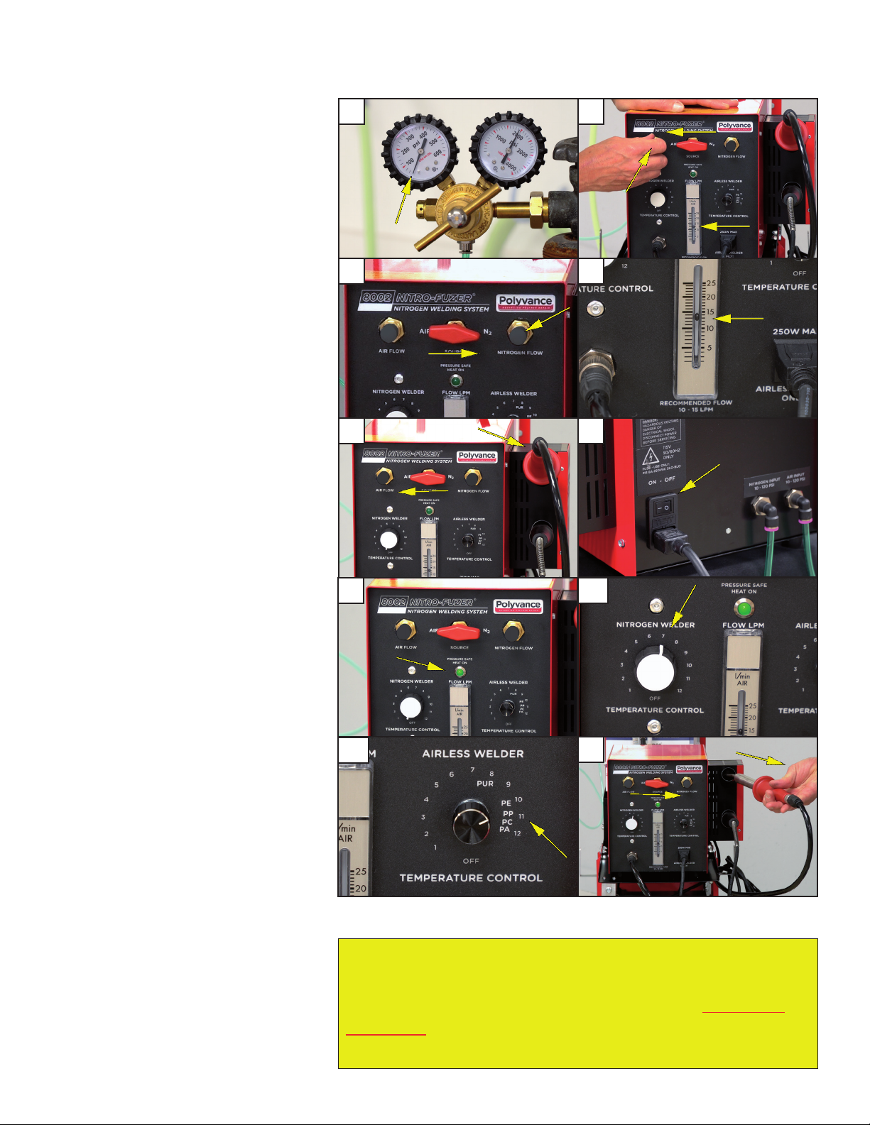
1. Most bumper repairs can be done with the air/nitrogen ow set at 12 LPM, but up
to 15 LPM is commonly used. The chart above may be used as a general guide for
welding various materials. Using settings outside the range on the chart is generally
not needed, unless you are welding unusually thin or thick material or if the material
you are welding has an unusually high or low melting point.
It’s important to note that when increasing the temperature without increasing the
airow, the heating element can be over-heated easily, causing a dramatic reduction in
the life-span of the element. Over-heating is indicated by a glowing outer steel torch
barrel. If this happens, immediately turn down the temperature and turn up the air and
nitrogen ow. If an over-heat condition continues uncorrected, the heating element
will burn out and the handle may be destroyed by the excessive heat becoming a
potential re hazard.
2. To change from air to nitrogen, simply turn the selector valve to the desired source.
Be sure to switch back to the air setting when the weld is complete to avoid using
excess nitrogen.
3. Once the welder has warmed up, welding is accomplished by directing the heated
nitrogen at the intersection of the area to be repaired on the base material and the
welding rod. The welding rod should be applied perpendicular to the base material
with the welder aimed at approximately a 45° angle between the two.
4. The substrate should begin to gloss over in 3 to 5 seconds after applying the heat.
At this point, begin pressing the rod downward onto the surface, rolling it towards the
heat. Be sure the surface of the rod and the surface of the substrate are both melted
when pushing the two materials together.
For more information on welding plastic, please watch the instructional videos found at
www.polyvance.com.
Welding Basics: 1
2
3
4
12 LPM
Temperature Setting Suggestions*
* Most welding operations will be at the recommended settings. Welding outside the recommended range may be needed if the plastic being welded is
very thin or thick or if a higher or lower airow is used. Extreme care must be taken to avoid overheating the element.
Type of Plastic Melting Temp. Series of
Welding Rod
Recommended Temperature
Setting on Nitrogen Welder Air Flow
Polyurethane (RIM, PUR) N.A. R01 8-10 (AIRLESS WELDER ONLY) N.A.
Polypropylene (PP) 160-166°C (320-331°F) R02 7 12
ABS 105°C (221°F) R03 6-7 12
Polyethylene (LDPE) 105-115°C (221-239°F) R04 7-8 12
TPO 177°C (350°F) R05 7-8 12
Nylon (PA) 269°C (516°F) R06 8 12
Polycarbonate (PC) 155°C (311°F) R07 7- 12
PPE+PS, PPO 260°C (500°F) R08 7 12
PVC 177°C (350°F) R09 6+ 12
FiberFlex®N.A. R10 12 (AIRLESS WELDER ONLY) N.A.
PBT (Polybutylene Terephthalate) 225°C (437°F) R11 7-8 12
Polyethylene (HDPE) 190°C (375°F) R12 7-8 12
PET 254°C (490°F) R13 8- 12
ASA 220°C (428°F) R14 6-7 12
GTX (Nylon blend) 275-300°C (527-572°F) R15 8 12
POM (Acetal, Delrin®) 215°C (419°F) R16 6+ 12
Acrylic/PVC (Kydex®) <204°C (<400°F) R17 6-7 12
PP+GF15 160-166°C (320-331°F) R18 7 12
HDPE+GF15 190°C (375°F) R19 7-8 12
PC+ABS 155°C (311°F) R20 7- 12
The shutdown procedure is VERY IMPORTANT for maximizing
the life of your heating element. You MUST maintain airow
through the heating element until it is completely cool. You
are in control of your heating element’s life! Polyvance
cannot warrant the heating elements for this reason.
Page 4
Welder Shutdown Procedure:
Welder will not turn on.
• Check power supply to welder.
• Check wall outlet for 120V.
• Make sure power strip is on.
• Turn on the main power switch.
• Check that all cords going to the welder are plugged in.
• Check fuse on the back of the welder.
Fuse blows.
• Check heating elements for shorts. Remove the hot air element* and unplug the airless welder from the control panel. Check the resistance of the
elements using an Ohm meter.
• Hot air welder: 26.0 ± 1.0 Ohm
• Airless welder: 53 ± 3.0 Ohms
• If out of range, or an open circuit is indicated, replace the faulty heating element.
• If elements check OK, turn the unit on with no elements installed. If the fuse continues to blow, contact Polyvance. If unit appears to function
normally without the elements installed, plug in the airless welder only and test. If unit continues to operate normally, shut power o󰀨, then reinstall
the hot air element and test. If unit trips circuit during either test, its safe to assume the fault lies within the last element installed.
Nitrogen welder does not heat or is not hot enough.
• Turn the main power switch on.
• Set the temperature to “7” and the airow to 12 LPM.
• Observe the green “safe” light. If the light does not come on, power will not be sent to the heating
element. If the light is not illuminated at 12 LPM, call Polyvance.
• If it still does not heat, check resistance of the heating element. (See above.)
• If no faults are found, call Polyvance.
Airless welder does not heat.
• Turn the main power switch on.
• Set the temperature to “12.” Low settings will produce very little heat.
• If still no heat, check resistance of the heating element (see above) or plug directly into a wall
outlet. If it does not get hot, the element is faulty; if it gets hot, the switch is faulty.
To shut o󰀨 individual welders:
Airless Welder:
Turn the airless welder control knob
counterclockwise until it clicks.
Nitrogen Welder:
Place welder into the top holster and
turn the nitrogen welder control knob
counterclockwise until it clicks.
System Shutdown:
1. Shut o󰀨 main power on the back of the
welder.
2. Close the valve on the nitrogen bottle,
but leave the compressed air connected
and on.
3. Allow the welder to completely cool
before disconnecting the air supply.
Diagnostics:
1128 Kirk Road, Rainsville, AL 35986
Tech Support: 800-633-3047
email: [email protected]
web: www.polyvance.com
1 2
3
Ah, cool
air!
REV: 10-2020

Other Polyvance Welding System manuals

Polyvance 6049-C Nitro Fuzer Lite User manual

Polyvance

Polyvance 6049-C Nitro Fuzer Lite User manual

Polyvance 6085-C User manual

Polyvance

Polyvance 6085-C User manual

Polyvance 6180 User manual

Polyvance

Polyvance 6180 User manual

Popular Welding System manuals by other brands

Ronch Ronch Weld 200MP user manual

Ronch

Ronch Ronch Weld 200MP user manual

CIGWELD WeldSkill 250 MIG Service manual

CIGWELD

CIGWELD WeldSkill 250 MIG Service manual

Draper acdc160p instruction manual

Draper

Draper acdc160p instruction manual

Hobart Welding Products Stickmate 160i owner's manual

Hobart Welding Products

Hobart Welding Products Stickmate 160i owner's manual

GYS HEAVYMIG 400-4 manual

GYS

GYS HEAVYMIG 400-4 manual

Pace Sodrtek ST 145 Operation and maintenance manual

Pace

Pace Sodrtek ST 145 Operation and maintenance manual

Praxair PROSTAR manual

Praxair

Praxair PROSTAR manual

HURNER WeldControl 2.0 630 user manual

HURNER

HURNER WeldControl 2.0 630 user manual

ESAB EMP 205ic AC/DC instruction manual

ESAB

ESAB EMP 205ic AC/DC instruction manual

GF Piping Systems ECOS 160 instruction manual

GF Piping Systems

GF Piping Systems ECOS 160 instruction manual

Kaliburn Spirit200a user manual

Kaliburn

Kaliburn Spirit200a user manual

Lincoln Electric Power Wave C300 Operator's manual

Lincoln Electric

Lincoln Electric Power Wave C300 Operator's manual

Miller Invision 352 MPa Auto-Line CE owner's manual

Miller

Miller Invision 352 MPa Auto-Line CE owner's manual

Miller Electric OM-230 owner's manual

Miller Electric

Miller Electric OM-230 owner's manual

Miller Electric Millermatic Vintage M-25 Gun owner's manual

Miller Electric

Miller Electric Millermatic Vintage M-25 Gun owner's manual

Miller XMT 304 owner's manual

Miller

Miller XMT 304 owner's manual

Kemppi MASTER MLS 1600 Operation instructions

Kemppi

Kemppi MASTER MLS 1600 Operation instructions

Kemppi Flexlite GX Series operating manual

Kemppi

Kemppi Flexlite GX Series operating manual

manuals.online logo
manuals.online logoBrands
  • About & Mission
  • Contact us
  • Privacy Policy
  • Terms and Conditions

Copyright 2025 Manuals.Online. All Rights Reserved.