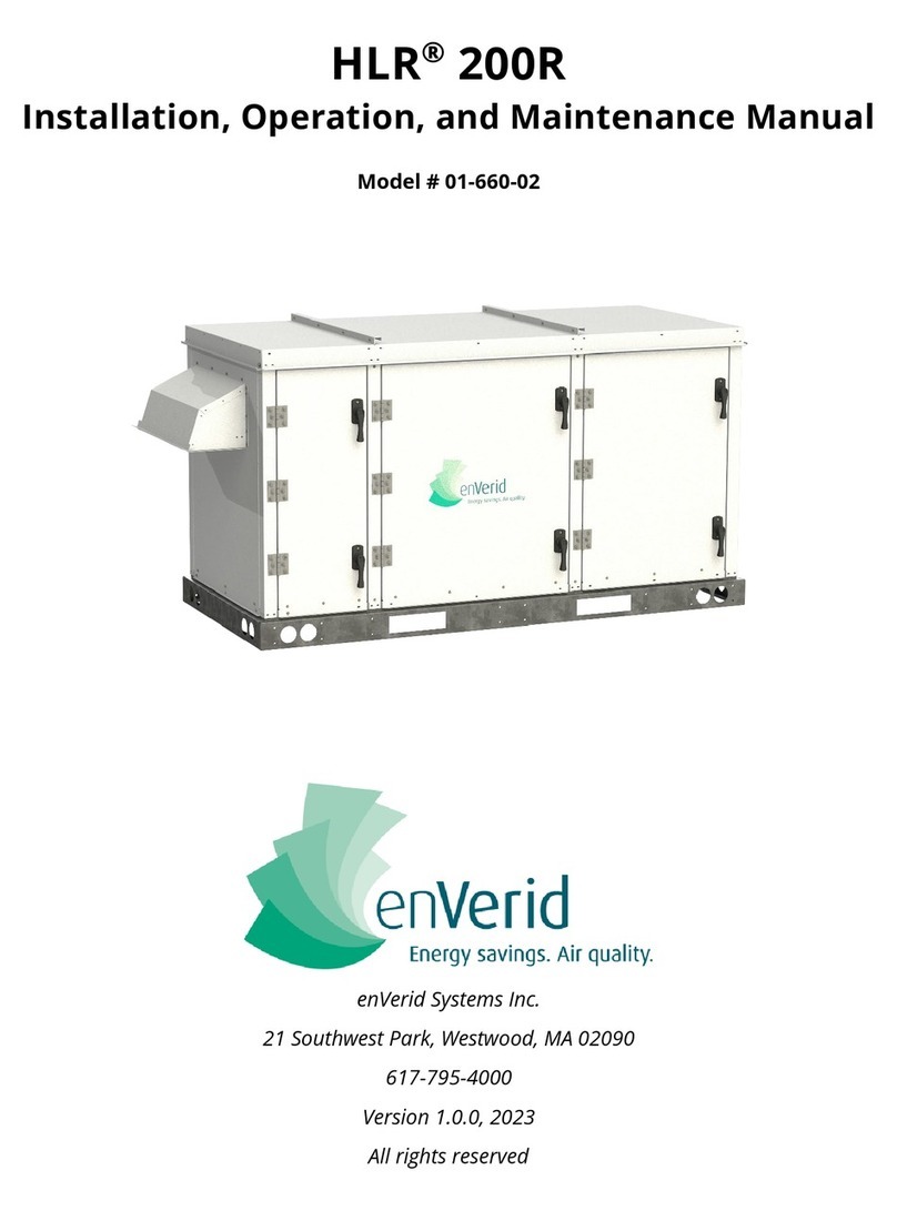
enVerid HLR 100M User manual

HLR®100M
Installation Manual
enVerid Systems Inc.
21 Southwest Park, Westwood, MA 02090
617-795-4000
Version 1.0.6, 2022
All rights reserved

i
Safety....................................................................................................... 1
HLR 100M Module Overview ................................................................. 2
HLR 100M Module Components....................................................................................2
Component Descriptions ................................................................................................3
Module Dimensions and Weights..................................................................................4
Maintenance and Service Clearance Requirements....................................................5
Installation ............................................................................................. 6
HLR 100M Module Installation .......................................................................................6
Installation Requirements...............................................................................................7
Ductwork Connections....................................................................................................8
HLR 100M Module Power .............................................................................................10
Hardwired Control Points................................................................................................ 11
Wiring Diagrams ................................................................................................................ 12
Accessing the Control Box............................................................................................... 14
Installing Sorbent Cartridges........................................................................................14
HLR 100M Hanging Bolt Installation ............................................................................18
Pre-Filter Replacement Procedure...............................................................................20
Initial Unit Startup..........................................................................................................21
Pre-Startup Checklist .......................................................................... 22
Service and Warranty .......................................................................... 23
Scheduled Service..........................................................................................................23
Warranty Summary........................................................................................................23
Warranty.............................................................................................................................. 23

HLR 100M Installation Manual
1
Safety
Read this manual in its entirety prior to performing any work on the HLR 100M module.
Follow the recommendations provided in this manual to ensure personal safety, proper
installation and operation, optimal performance, and maximum module life.
WARNING! Personnel untrained to work with electrical equipment may be seriously
injured or killed if allowed to work on the HLR 100M module. Do not attempt
to perform any electrical work without proper personal protection
equipment.
•Do not alter, puncture, or cut into the casing of the HLR module at any location
without prior written approval from enVerid Systems Inc.
•All work performed on the HLR 100M module must comply with local and state
codes, federal regulations, the construction documents, and this manual.
•Only authorized, trained, and certified personnel should perform or supervise any
work on the HLR 100M module.
•Only qualified licensed electricians should perform any electrical work exterior to
the HLR 100M module.

HLR 100M Installation Manual
2
HLR 100M Module Overview
HLR 100M Module Components
The HLR 100M module can be installed in either a vertical or horizontal orientation.
Descriptions and procedures for both configurations are given in this manual.
Each HLR 100M module is a self-contained cabinet pre-assembled with the components
shown below.
Figure 1 HLR 100M Component Location and Description

HLR 100M Installation Manual
HLR 100M Module Overview
3
Component Descriptions
•HLR module Casing: The casing is made of a single-wall, galvanized steel construction
with powder-coated paint.
•Sorbent Cartridge Bank: The sorbent cartridge bank houses 12 sorbent cartridges that
capture contaminants of concern (VOCs, aldehydes, carbon dioxide, and other
inorganics).
•Fans: Integrated DC, brushless fans control airflow through the HLR 100M module.
•Control Box: Protected electrical component enclosure that houses the electrical point
of connection and fan speed controller.
•Indoor Air Inlet: 18” X 18” flanged inlet for indoor air.
•Clean Air Outlet: 12” X 12” flanged outlet with integral bird screen.
•Main Power Pathway: External power connection port with 1" conduit adapter.

HLR 100M Installation Manual
HLR 100M Module Overview
4
Module Dimensions and Weights
Figure 2: 100M Module Dimensions
Table 1: Dimensions and Weights
HLR 100M Dimensions (Including Dampers and Handles)
Vertical Configuration
Height 58.20” / 1,478 mm
Width
24.86” / 631.5 mm
Depth 25.75” / 654 mm
Horizontal Configuration
Length 58.20” / 1,478 mm
Height
24.86” / 631.5 mm
Depth 25.75” / 654 mm
Inlet Duct Connection
17.88” / 454 mm X 17.88” / 454 mm
Outlet Duct Connection 11.88” / 302mm X 11.88” / 302 mm
W eight
Module Shipping Weight
150 lb/68.2 kg
Cartridge Shipping Weight 198 lb/90 kg
Module Installed Weight
348 lb/158.2 kg

HLR 100M Installation Manual
5
Maintenance and Service Clearance Requirements
The area around the HLR 100M module should be kept clear for maintenance and service.
The following diagrams show the clearances to be maintained for proper operation and
installation, as well as the clearances required for servicing the module.
CAUTION: Keep the area in front of the control box clear of obstructions as required by
the local electrical code.
Figure 3: HLR 100M Minimum Clearances

HLR 100M Installation Manual
Installation
6
Installation
HLR 100M Module Installation
Each HLR 100M module with pre-filter is shipped in its own container. The sorbent
cartridges are shipped in separate cartons.
Note: The sorbent cartridges may arrive separately from the HLR modules.
If any damage to the packaging for the HLR 100M module(s) is visible upon receipt, inspect
the package further to see if there is any damage to the contents.
If the project is not ready for installation, store the HLR 100M module(s), pre-filter(s) and
cartridge set(s) in the original packaging, in the proper orientation, and place them in a dry,
clean, indoor space that minimizes fluctuations in relative humidity and maintains a
temperature between 40 °F (4.4 °C) and 85 °F (29.4 °C) . The pre-filters and sorbent
cartridges must remain dry while in storage.
When the project is ready for the HLR 100M module(s) to be installed, remove the module
from its container and inspect it for any defects or damage. Report any problems to your
local sales representative.
Each HLR 100M module comes with 4 X threaded holes on top and bottom of the unit for
hanging the unit or installation of threaded feet for floor-mounted applications.
We recommend unloading the module close to the installation site or placing it on corner
dollies for easy transport.
Transport the HLR 100M module to its installation location and place in the orientation
required for the installation.
Note: The HLR 100M operates in either a horizontal or vertical configuration.

HLR 100M Installation Manual
Installation
7
Locate the module so that the proper clearances are maintained in either orientation, as
shown in the Figure 5.
Once the HLR 100M module has been set in place, it is ready to be connected to the return
air ductwork or plenum, electrical power, and controls.
Installation Requirements
Note: HLR 100M module(s) should be installed per local and federal code
requirements.
Prior to installation, review the drawings issued for construction, any bulletins or addenda
received, and requests for information responses pertaining to the installation of the HLR
100M module(s). Ensure that installation of the module(s) is done in accordance with the
approved coordination drawings and that proper service and maintenance clearances are
maintained.
The location of the HLR 100M module(s) is determined by the installation criteria discussed
in the HLR Design Manual. Some of the considerations are:
•Unit geometry
•Clearances in the mechanical room
•Proximity to the return air duct
•Placement: The HLR 100M module can be set on the floor or hung in a horizontal
position, or hung in a vertical position
•Ensure that the HLR 100M module has the correct single phase power connected
oNorth America: 208V or 277V, 60Hz
oInternational: 220V to 240V, 50 or 60Hz
•Provide a disconnect switch that can be locked in the off position, mounted
externally to the unit
If the HLR 100M module(s) location does not appear to be suitable, request clarification
from the design team.

HLR 100M Installation Manual
Installation
8
Prior to setting the HLR 100M module(s) in the mechanical room, verify from the contract
documents that a housekeeping pad is not required.
For additional technical support required during installation or operation, contact the
manufacturer.
Ductwork Connections
The HLR 100M was designed to be installed in a plenum or in the space that it is cleaning.
The figure below shows how to set up the HLR 100M for a plenum/space installation.
Note: Field installed ductwork cannot be smaller than the damper opening as this
will impact the damper blade travel.
For ducted connections, see Figure 4.

HLR 100M Installation Manual
Installation
9
Figure 4: HLR 100M Duct Connections
A
Indoor Air Inlet: Connected to return air ductwork via a duct connection or
terminated as an open end with bird screen (architectural grille also acceptable).
B
Clean Air Outlet: This port is normally connected to a short length of ductwork, 2” or
longer. This ductwork can be straight or elbowed to direct the cleaned air toward the
mixing box. This port should terminate as an open end with bird screen (architectural
grille also acceptable). Overhead clearance should be provided to maintain proper
flow.
The inlet air and clean air outlet ductwork should be connected to the appropriate air
handling units return air ductwork, or as shown on contract drawings.
The ductwork should be separated by the amount shown on contract drawings or in the
HLR Technology Design Guide. The inlet and outlet ductwork connections should be
separated by a minimum of four (4) equivalent duct diameters. The HLR 100M can be
installed as a single module, or in a cluster (multiple modules connected by common
ductwork and acting as a single module).
The ductwork should be supported from the building structure. However, the electrical
conduit for the HLR module(s) must be supported by its own supports, that is, the electrical
conduits cannot be supported by the supports for the ductwork.
A
B

HLR 100M Installation Manual
Installation
10
Neither the ductwork nor the electrical conduits can be supported off any existing supports
or a support installed by any other trade without approval of the engineer of record. A
flexible connector should be installed between the ductwork and the HLR 100M. The
connector isolates the HLR 100M from the ductwork and minimizes the use of the module
duct connectors to support the ductwork.
Ductwork should be insulated per local codes and installed in accordance with the contract
documents.
HLR 100M Module Power
Note: HLR 100M module(s) should be installed per local and federal code
requirements.
All requirements for wires, cables, raceways, and pull boxes should be verified in
accordance with the project contract documents. All wiring should be installed in
accordance with the local electric code (NEC with local amendments).
All conductors installed to supply power to the HLR 100M module(s) should be sized in
accordance with the contract documents and local electric code. All wiring should be color
coded in accordance with the electrical code. The wiring should include the required
number of phase conductors, neutral, and full-size insulated (green) ground conductor.
Each HLR 100M module has a connection point for the branch conduit. The module should
be connected to the branch conduit via a flexible connector. See the contract documents
and local electrical code for length limitations. Coordinate the location of the power
conduit, and the final location of the HLR 100M module(s) with the mechanical contractor
and general contractor.
CAUTION: Only use the electrical connection as specified above. Do not drill any holes in
the HLR module casing without prior written consent from the manufacturer.
The input power is based on the available voltage, as defined in Table 2.

HLR 100M Installation Manual
Installation
11
Table 2: HLR 100M MCA/MOCP Ratings – 530W
Voltage In (VAC) M CA (Ra ting) M OCP (Ra ting)
@277
3.05 A
15 A
@230 3.25 A 15 A
@208
3.50 A
15 A
Table 3: HLR 100M MCA/MOCP Ratings – 550W
Voltage In (VAC) M CA (Ra ting) M OCP (Ra ting)
@277
3.15 A
15 A
@230 3.28 A 15 A
@208
3.60 A
15 A
Provide a disconnect switch that is rated for 480 V. The enclosure for the disconnect switch
shall have a minimum NEMA rating of 3R or greater, if called for in the contract documents.
The disconnect switch should allow locking in the off position to conform to the
project/building's Lock Out Tag Out (LOTO) requirements.
The disconnect switch can be mounted on a Unistrut stand next to the HLR module or on a
nearby wall.
Hardwired Control Points
The module can be hardwired to the building automation system via two pairs of 18 AEG
wire connected to the single 14 VAC/DC relay located within the HLR 100M Module control
box.
The relay controls Start/Stop for the unit and is required to isolate the HLR Module‘s 24
VDC powered control board from the Building Management System’s 24 VAC power. The
wiring contractor should only be wiring between the installed relays and the BMS. The
wiring between the relays and control board is done at the factory.
The BMS supplies 24 VAC to the HLR Start/Stop Relay when the correct conditions are met
to operate the Module/Cluster.
Optional 0-10VDC Fan Speed Control available. Factory mounted potentiometer allows for
manual control for balancing.

HLR 100M Installation Manual
Installation
12
See wiring diagram on page 14.
Table 3: Hardwired Points
Control Point Name Type
HLR Start/ Stop
Binary Output from the BAS
Fan Speed Control
0-10VDC from the BAS
Wiring Diagrams
Figure 5: 530W Wiring Diagram

HLR 100M Installation Manual
Installation
13
Figure 6: 550W Wiring Diagram

HLR 100M Installation Manual
Installation
14
Accessing the Control Box
Follow the steps below to access the control box.
Figure 7: Accessing the Control Box
Installing Sorbent Cartridges
Before the arrival of support personnel on site, install the sorbent cartridges according to
the instructions below.
This section describes how to properly install new sorbent cartridges and verify the seal in
the module. Before beginning this procedure, make sure you have all personal protection
equipment that is required which should include the following:
•Work gloves
•OSHA- or company-approved work shoes
This procedure requires only a 5/16” or 8mm nut driver.
Remove static current
WARNING! Do not remove the cartridge access door without powering down the
module, turning off the electricity, and locking the electrical cabinet.

HLR 100M Installation Manual
Installation
15
Figure 8: Remove Cartridge Access Door
To remove the cartridge access door:
4. Remove 6 X bolts (4) from left and right of cartridge bank access door (5) using 5/16”
wrench or socket.
5. Loosen remaining 2 X bolts (4) enough that panel (5) can be lifted and slid in keyhole
to allow removal of panel over the bolts.
6. Once panel is removed. 12 X sorbent cartridges can be removed and replaced.
Replace cartridges in V-bank arrangement so that protrusions on cartridges fit into
sheet metal channels on both sides.
7. To replace panel, slip large portion of keyhole over 2 X bolts that were not removed
and slide sideways into place. Replace 6 X bolts and tighten all 8 X bolts.
WARNING! When in a high wind area such as a plenum, secure the removed cover.
The cover may be pulled by moving air and cause injury to persons or
damage to equipment.

HLR 100M Installation Manual
Installation
16
Figure 9: Sorbent Cartridge V – Bank Arrangement
CAUTION: Use only hand tools. Using a power tool may strip the threads in the cartridge
cabinet and degrade the quality of the seal.
CAUTION: Before handling the sorbent cartridges, read the Safety Data Sheet that is
included in the shipping carton.
When handling sorbent cartridges, always hold them by the outside edge. If
the fabric seal on the grid sorbent cartridge body is torn or punctured, send
photos of the damaged cartridge to the manufacturer so they can be
reviewed to determine if the cartridge can be repaired or should be
discarded. Follow all written instructions in the return email.
Use gloves when handling sorbent cartridges.
CAUTION: Care should be taken to prevent the cartridges from getting wet. If the
cartridges should happen to get wet in transit, contact your local support
representative.

HLR 100M Installation Manual
Installation
17
CAUTION: Do not crush or perforate sorbent cartridges during handling.
1. To insert the first sorbent cartridge, open the carton and remove the top one by
grasping the outside edge.
For vertical configurations, set one edge of the sorbent cartridge in the second rail
from the right.
For horizontal configurations, set one edge of the sorbent cartridge in the second
rail down from the top.
Note: The top/right rail is not used.
2. Make sure that the sorbent cartridge is over the rubber gasket.
3. Bring the sorbent cartridge toward the opposite rail and make sure that the rubber
gaskets are pushed in sufficiently to allow the sorbent cartridge to be on both
gaskets at the same time.
4. Slide the sorbent cartridge in by holding the outer edge.
CAUTION: Do not use any soap or lubricant on the flexible seal during the insertion
process. This may damage the sorbent cartridge bank.
Note: Be firm when inserting the sorbent cartridge, but do not force it. If the
sorbent cartridge stops, remove it and try again. Double-check and ensure
that it is in the correct tracks on both sides.
5. Slide the sorbent cartridge in until it is well-seated against the rear wall gasket.
Verify that it is well-seated against the back wall.
6. Continue installing the rest of the twelve sorbent cartridges.
Note: Each pair of the sorbent cartridge form a V-shape. This configuration is crucial
for correct operation.

HLR 100M Installation Manual
Installation
18
HLR 100M Hanging Bolt Installation
Before beginning this procedure, make sure you have all personal protection equipment
that is required which should include the following:
•Work gloves
•OSHA- or company-approved work shoes
This procedure requires a 5/16” or 8mm nut driver and 9/16” wrench or socket.
Remove static current
Figure 10: Hanging Bolt Installation Detail - Vertical
Other manuals for HLR 100M
1
Table of contents
Other enVerid Industrial Equipment manuals
Popular Industrial Equipment manuals by other brands
Mayr
Mayr ROBA-DS 956 Series Installation and operational instructions
Grundfos
Grundfos CMB-SP Booster PM2 installation instruction and operating instructions
Matsing
Matsing MS12C90 instruction manual
Siemens
Siemens CASTOMAT ION ANALOGINPUT T001 manual
Eaton
Eaton Airflex HEVC 5005 Installation, operation and maintenance manual
SMC Networks
SMC Networks ZQ Series Operation manual
