Installation and Operational Instructions for
ROBA®-DS Couplings Type 956. _ _ _
Sizes 2200 –11000 (B.9.7.3.EN)
12/11/2015 RM/GC Chr. Mayr GmbH + Co. KG
Eichenstraße 1, D-87665 Mauerstetten, Germany
Tel.: +49 8341 804-0, Fax: +49 8341 804-421
Page 4 of 6 www.mayr.com, E-Mail: info@mayr.com
Shaft-Hub Connection
The torque values stated in Table 1 do not necessarily apply to
the shaft-hub connection. For the shaft-hub connection, a
strength verification must be carried out depending on the shaft
design and the application using appropriate calculation methods
(e.g. DIN 6892 for key hubs). For the hubs, a yield point of 2
75 N/mm² and a tensile strength of 560 N/mm² can be used for
the calculation.
Guidelines on Hub Bore and Shaft
The hub bores are usually produced with tolerance H7. The
required shaft tolerance depends on the hub type used as well
as on the basic overall load configuration.
The shaft surfaces should be finely turned or ground
(Ra = 0.8 µm).
Hub Installation
Hubs with external shrink disks
The force is transmitted via frictional locking. Therefore, the
hub bores and the shaft ends must be completely oil and
grease-free during installation. Greasy or oily bores or shafts
reduce the transmittable torque.
The shafts must not have a keyway.
Mount the hubs onto the shafts using a suitable device, bring
them into the correct position and mount the shrink discs
following the Installation Instructions available separately
(Installation Instructions for shrink discs of the types TAS 30.. /
TAS 52..).
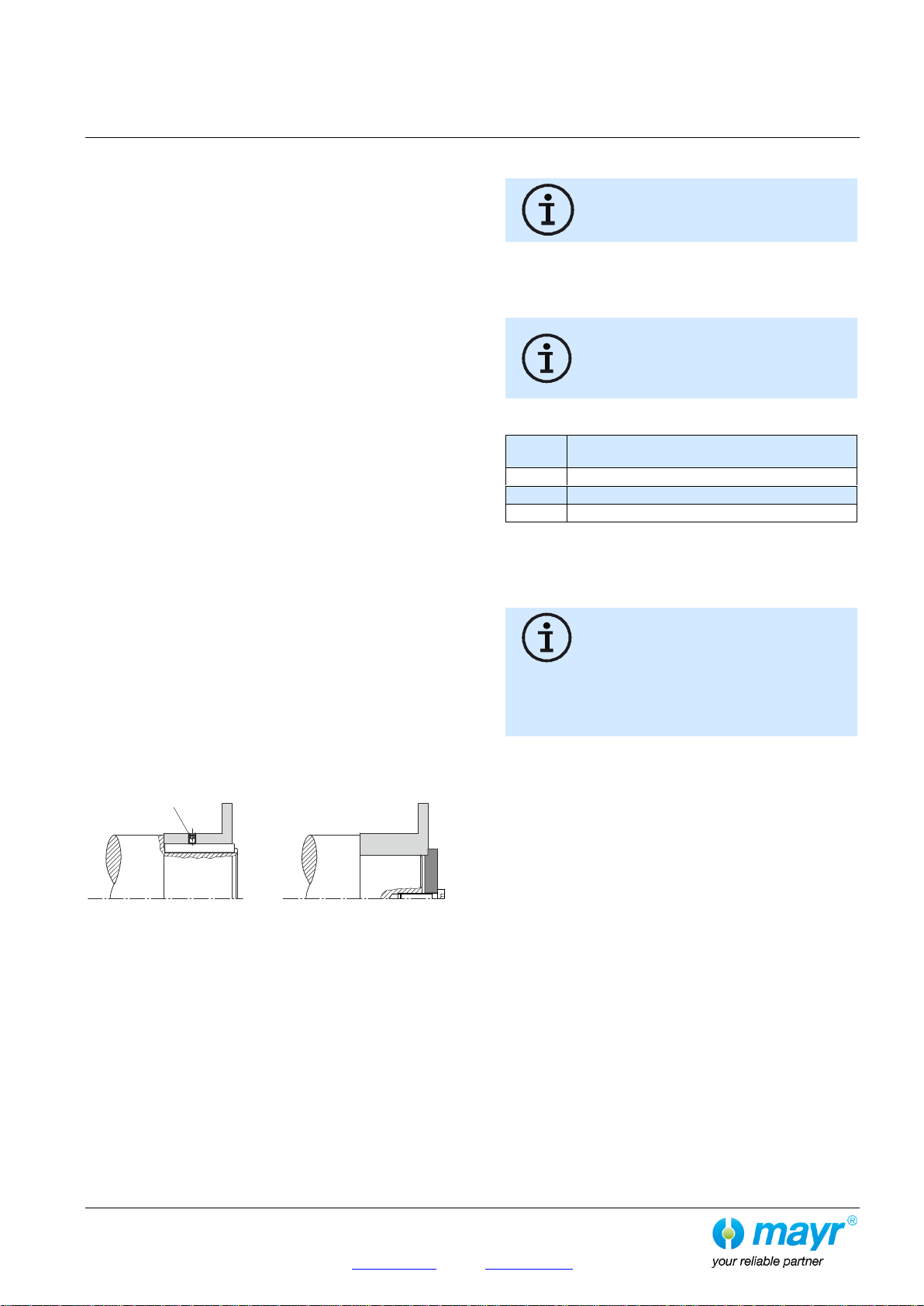
Hubs with Keyway
Mount the hubs onto the shafts using a suitable device and
secure them axially (Fig. 3). Axial securement takes place
using a set screw (adjusting screw), which presses radially
onto the key (tightening torques acc. Table 1, page 3); or via a
press cover and a screw, screwed into the shaft threaded
centre hole.
The key must lie over the entire length of the hub.
Adjusting screw
Fig. 3
Coupling Installation
The conical exterior surface of the cone bolts
(10) (including the O-rings (11)) must be
greased with “Klüber Altemp Q NB 50”.
The disk packs (2) are mutually connected with the hubs (1), the
sleeve (3) or the flanges (4) via the cone bolts (10); they are
screwed together via the lightly oiled hexagon head screws (5)
and press covers (6) (Fig. 1a).
The hexagon head screws (5) must be
tightened in several steps to their full
tightening torque acc. Table 1. Please see
Table 2 for the respective tightening torques
for each step.
Table 2
Tightening torques for hexagon head screws
(5)
30 % of the nominal tightening torque
60 % of the nominal tightening torque
100 % of the nominal tightening torque
The hexagon head screws (5) on each connection side must be
tightened cross-wise.
The disk pack (2) must not under any circumstances be distorted
when applying the pre-tension force.
In principle, the disk pack (2) is inserted in a
way so that the press covers (6) press onto
the rings (7) of the disk pack (2). The press
covers (6) do not press onto the collar
bushings (8). See Fig. 1a, page 2.
When inserting the press cover (6), please
make sure that the installation direction is
correct. See Fig. 1a, page 2.
For de-installation of the disk pack (2), the hexagon head
screw (5) is screwed out and together with the press cover (6)
screwed into the cone bolt (10) on the opposite side.
When doing this, please make sure that the installation direction
of the press cover (6) is correct; see Fig. 2, page 2.
This loosens the cone bolt (10) and it can be pulled back axially.
Then, the disk pack (2) can be removed radially (Fig. 2, page 2).