5
Fig. 1
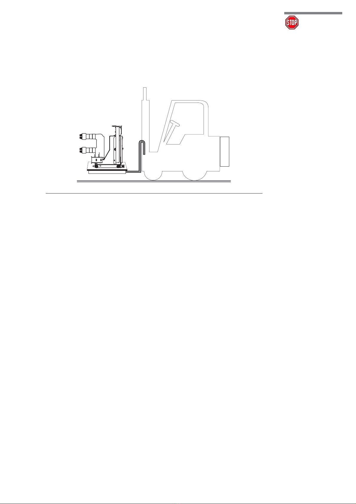
1. Packing and transport
The circuit-breaker is shipped in special packing, in the open position.
Each piece of apparatus is protected by a plastic cover to prevent any infiltration of water during
the loading and unloading stages and to keep the dust off during storage.
2. Checking on receipt
Before carrying out any operation, always make sure that the capacitors are discharged
and that the apparatus is in the open position.
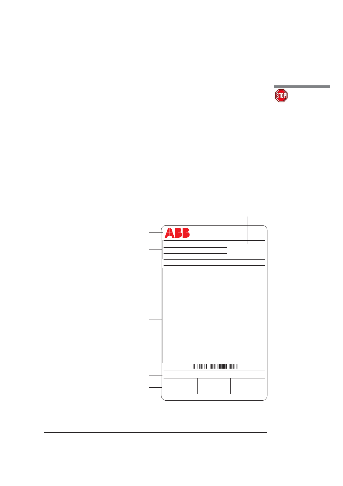
On receipt, check the state of the apparatus, integrity of the packing and correspondence with the
nameplate data (see fig. 1) with what is specified in the order confirmation and in the accompany-
ing shipping notes.
Also make sure that all the materials described in the shipping notes are included in the supply.
Should any damage or irregularity be noted in the supply on unpacking, notify ABB (directly or
through the agent or supplier) as soon as possible and in any case within five days of receipt.
The apparatus is only supplied with the accessories specified at the time of ordering and vali-
dated in the order confirmation sent by ABB.
Caption
A Circuit-breaker rating plate.
B Drive rating plate.
1 Type of apparatus.
2 Symbols of compliance with Standards.
3 Serial number.
4 Circuit-breaker characteristics.
5 Characteristics of the drive auxiliaries.
Warning!
A
B
3
4
2
CIRCUIT-BREAKER IEC 62271-100
eVM1 ... ... ... CEI 17-1
CLASSIFICATIONSN ... ... ...
SN ... ... ... PR. YEAR ......
M MASS ... kV
Ur VOLTAGE ... A
Up LIGHTING IMPULSE WITHSTAND VOLTAGE ... kV
Ud CORRENTE TERMICA NOMINALE ... A
fr FREQUENCY ... Hz
Ir NORMAL CURRENT
WITH FORCED VENTILATION BY ABB DESIGN
Ik SHORT TIME WITHSTAND CURRENT
tk DURATION OF SHORT CIRCUIT
Isc SHORT CIRCUIT BREAKING CURRENT
MAKING CAPACITY (PEAK VALUE)
AT THE VOLTAGE OF
D.C. COMPONENT ... A
Ic CABLE CHARGIMG BREAKING CURRENT ... A
Prn SF6 FILLING PRESSURE AT 20 °C ... kV
m SF6 MASS FOR CIRCUIT-BREAKER ... Kg
OPERATING SEQUENCE O-0,3S-C0-15S-CO
ELECTRICAL DIAGRAM ... ... ... ...
FIG. ... ...
.. ... ... ... OPERATING MECHANISM
-MO1 ... ... ... V
Made by ABB
1
5
The accompanying documents inserted in the
shipping packing are:
– instruction manual (this document)
– test certification
– identification label
– copy of the shipping documents
– electric wiring diagram.
Other documents which are sent prior to
shipment of the apparatus are:
– order confirmation
– original shipping advice notes
– any drawings or documents referring to special
configurations/conditions.