AFL Hyperscale SWR 1200 ODF User manual

SpiderWeb Ribbon®Optical Distribution Frame
SWR®1200 ODF
Installation Guide
2© AFL Hyperscale. All rights reserved
Safety Precautions
Laser Precautions
Warning: The laser light used to transmit information over optical ber cables can cause severe eye
damage. Because this light is invisible, it will not cause the iris of the eye to contract involuntarily as when
viewing a bright visible light, and no pain is felt as the retina is burned.
Never look into the end of a ber or connector which may have a laser coupled to it. Should accidental
eye exposure to laser light be suspected, arrange for an eye examination immediately.
General Precautions
Personnel must be thoroughly familiarized with all applicable Occupational Health and Safety (OH&S)
regulations, local regulations, and your company safety practices and policies.
Warning: To reduce the chance of accidental injury:
Before work begins, all personnel must be thoroughly familiar with the operation of all equipment
and procedures to be used during the installation.
Before use, all equipment, especially safety gear, must be inspected and tested for proper operation.
Replace and repair as necessary.
SWR®ODF 1200 Installation Guide
Before installing or adjusting this product, please read these instructions carefully.
Please keep this guide for future reference.

3
SWR®1200 ODF Installation Guide
© AFL Hyperscale. All rights reserved
Contents
Component Overview
ODF Components
Moving the ODF
The ODF System Layout
Recommended Installation Methods
Feeding of Cable
Feeding of Ribbon Fiber Cable
Installing the U-Series Solution
Cassette Tail Routing
Patchcord Routing
04
10
21
06
11
13
08
17
09
20
4© AFL Hyperscale. All rights reserved
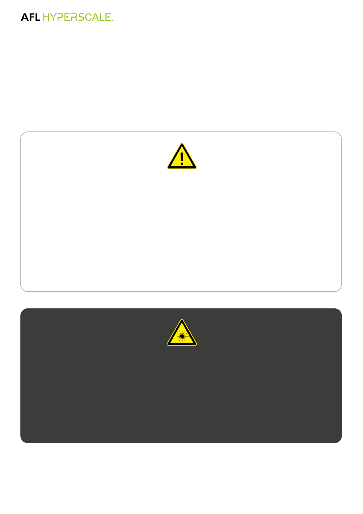
Component Overview
Internal
Distribution
Area
External
Distribution
Area
Core Kit
Area
A
BC
D
Item Item Qty
A Front access Frame 1
BU-Series 1RU front Access Fiber
Management 4
C U-Series 2RU Housing 2
DU-Series Front Access Cassette
(Not Supplied with frame) 0
(A) Front access Frame
(C) U-Series 2RU Housing (D) U-Series Front
Access Cassette
(B) U-Series 1RU front
Access Fiber Management
5
SWR®1200 ODF Installation Guide
© AFL Hyperscale. All rights reserved
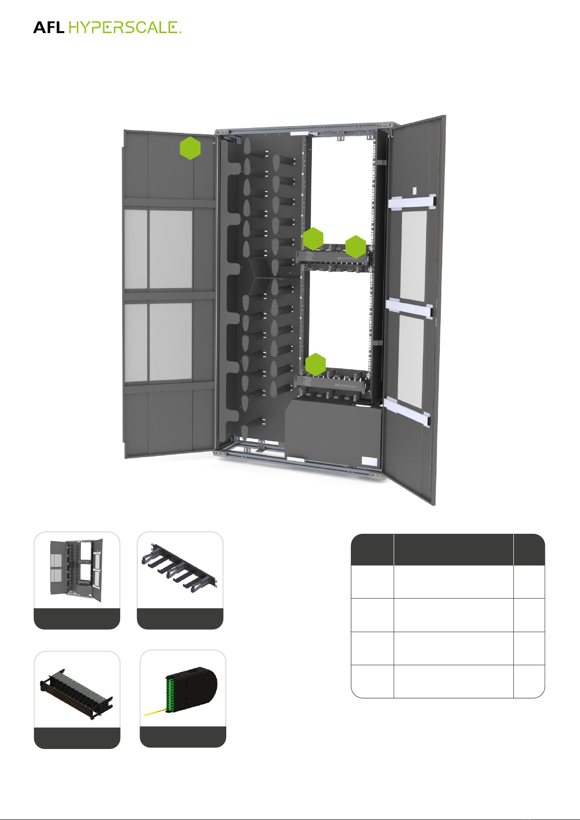
Internal
Distribution
Area
Exit Cable Point
Anchor Points
Patch cord
Separator
Top feed frame
and inbound
route divider
External
Distribution
Area
Core Kit
Area
H
F
G
Item Item Qty
E SWR Snap Fit Transition Box 2
F Spool 27
G Door Labeling 2
H Lockable splice area (Top Fed) 1
(G) Door Labeling
(E) SWR Snap Fit
Transition Box
(G) Lockable Splice Area
(Top Fed)
(F) Spools
Component Overview
6© AFL Hyperscale. All rights reserved
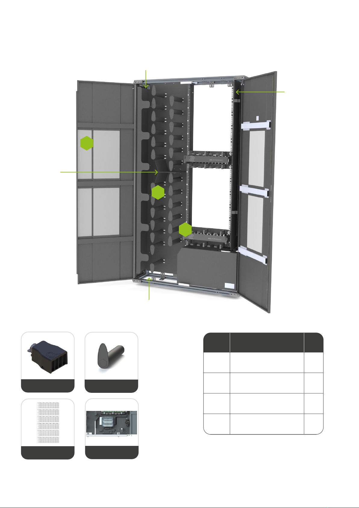
1. Entry Cable Point
2. 144 Fiber Ribbon Splice Tray
3. Slack Basket
4. SWR Snap Fit Transition Box Kit
ODF Components
2
34
1
Front door: Front removable hinged door. Labelling
position on reverse for clear port identication and label
card included
Front and rear installation: Cassettes can be securely
installed and xed inside the chassis by an easy-access
latching mechanism. Each module can be installed from
the front or rear.
Cassette Slot: Up to 12 cassette in 2RU - 288 LC ports.
Front Management: Large cable management rings for
Outgoing Patch cord 2.0mm Cable.
Top/ Bottom Cable: Top and Bottom cable management
ring for Incoming 3.0mm cable.
Cable Support: Cable support for Outgoing Patch cord
2.0mm Cable.
U-Series 2RU Housing U-Series 1RU Fiber Management
Lockable Splice Area
Simplied Cassette Access
Convenient locking push latch for front and rear access.
Shuttered LC Quad Adapter
Shutter adapter for improved cleanliness and laser safety.
Cassette Tail: 24F 3.0mm cassette tail.
U-Series 24F
Tailed cassette

7
SWR®1200 ODF Installation Guide
© AFL Hyperscale. All rights reserved
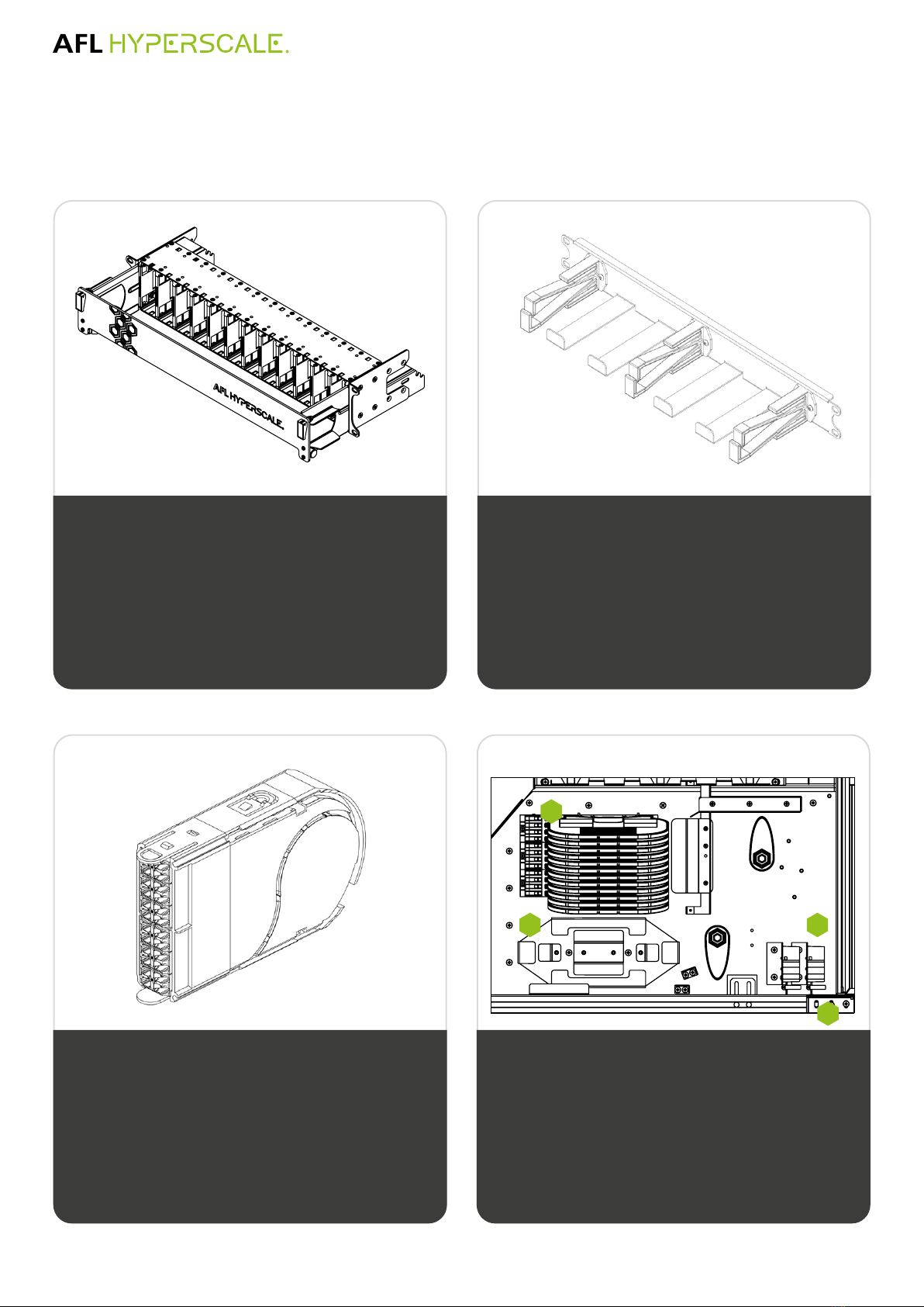
ODF Components
SWR Snap Fit Transition Box Kit
1. Transition Lid
2. Transition Base
3. Cable Fixing Point
4. 12 x 0.7 Meter 10MM OD Corrugate Tubing
5. Label Set

8© AFL Hyperscale. All rights reserved
Packaging/Handling of the ODF
The frame is packaged on a pallet vertically layout. Proceed to safely transport the unit to location using a forklift
or heavy lifting equipment.
1
Once in the desired position, continue by removing the packaging from the Frame, and release the bottom
anchor to free the unit. Proceed to remove the front and side doors of the frame by detaching the top and
bottom hinges on the door. Once done, lift the frame from its packaging close to the nal location.
2
CAUTION
CAUTION: The ODF
weighs approx.
112kg. Manual
handling training
and appropriate
equipment is required
for installation.
Side View ISO View Front View

9
SWR®1200 ODF Installation Guide
© AFL Hyperscale. All rights reserved
The ODF System Layout
WALL MOUNTED SIDE BY SIDE
BACK TO BACK END OF AISLE
600mm 1200mm
600mm
600mm
300mm
2400mm
600mm
600mm
300mm
1200mm
600mm
600mm
600mm
600mm
300mm 1200mm
10 © AFL Hyperscale. All rights reserved
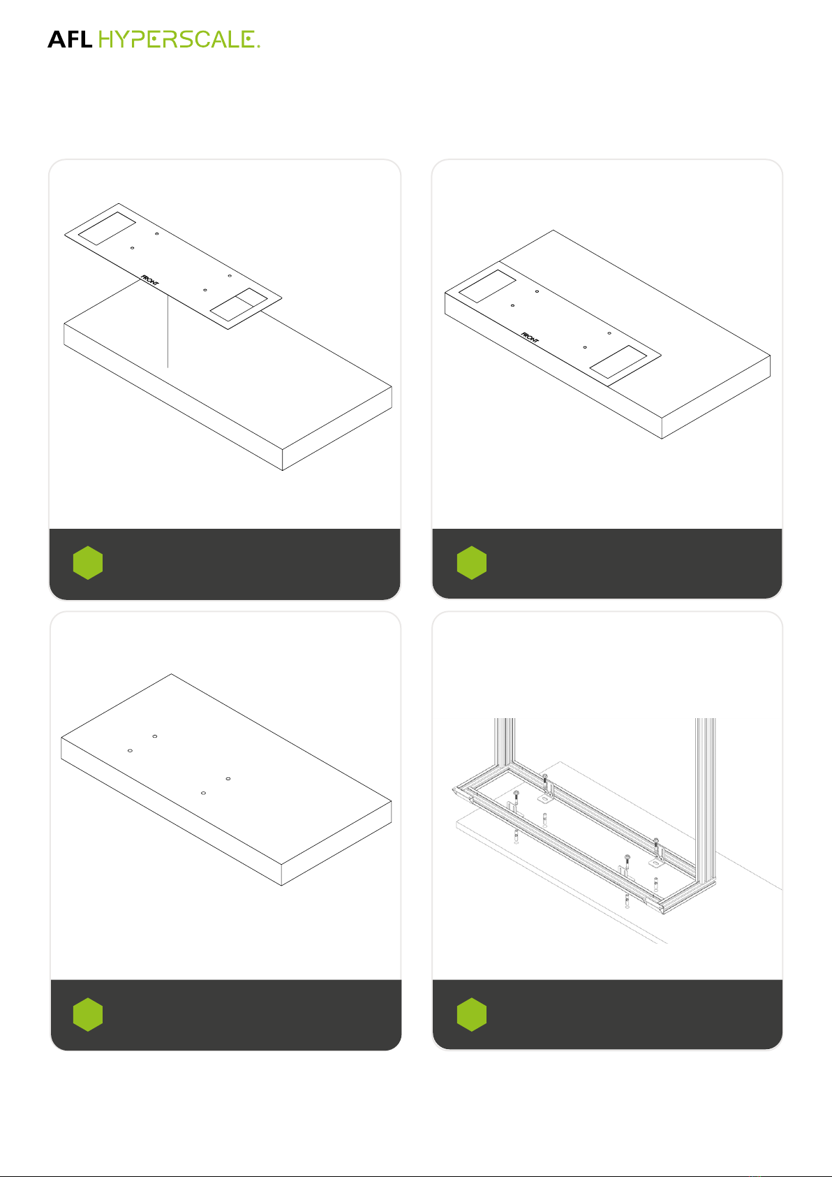
Recommended Installation Methods
Direct to Concrete Floor
Place the supplied template on the oor Mark out the holes
Drill the holes
Place the frame into position and remove the cover
for the splice area to gain access to the anchor points.
Once done, proceed to press in and tighten the M10
anchor bolt throught the base of the frame
1 2
3 4
11
SWR®1200 ODF Installation Guide
© AFL Hyperscale. All rights reserved
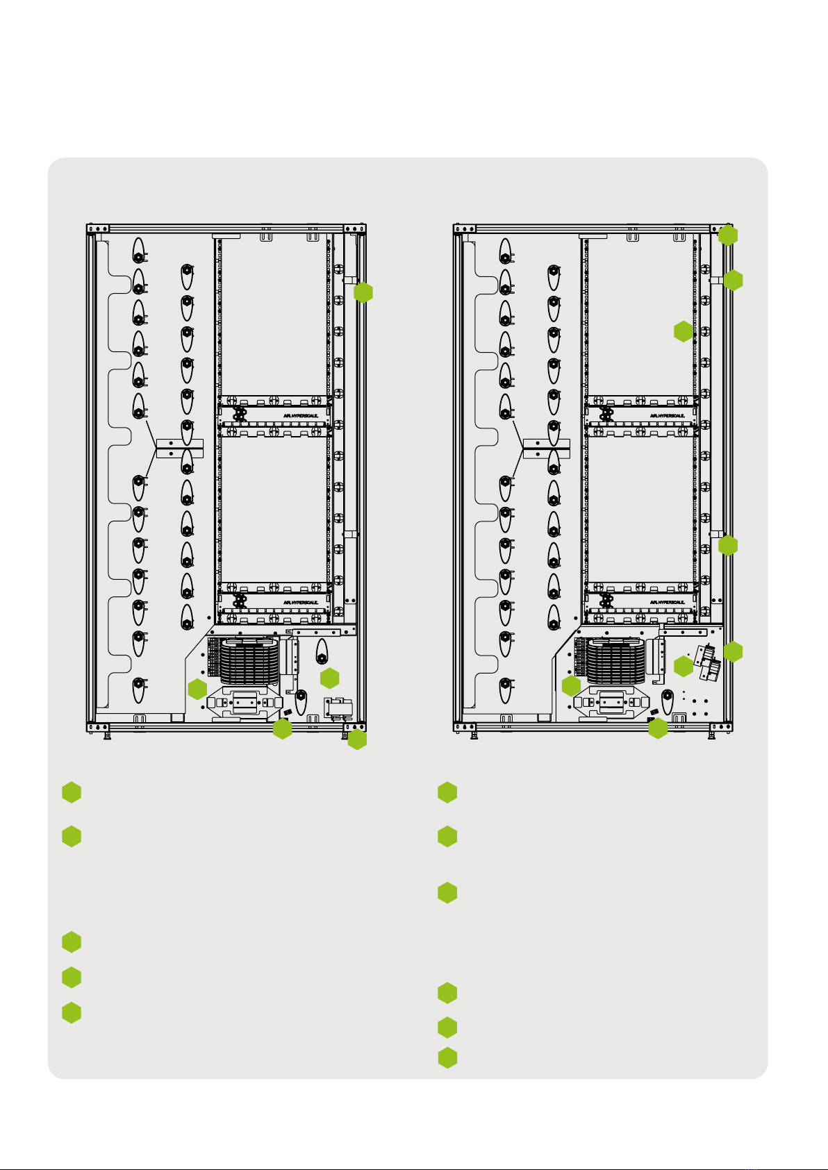
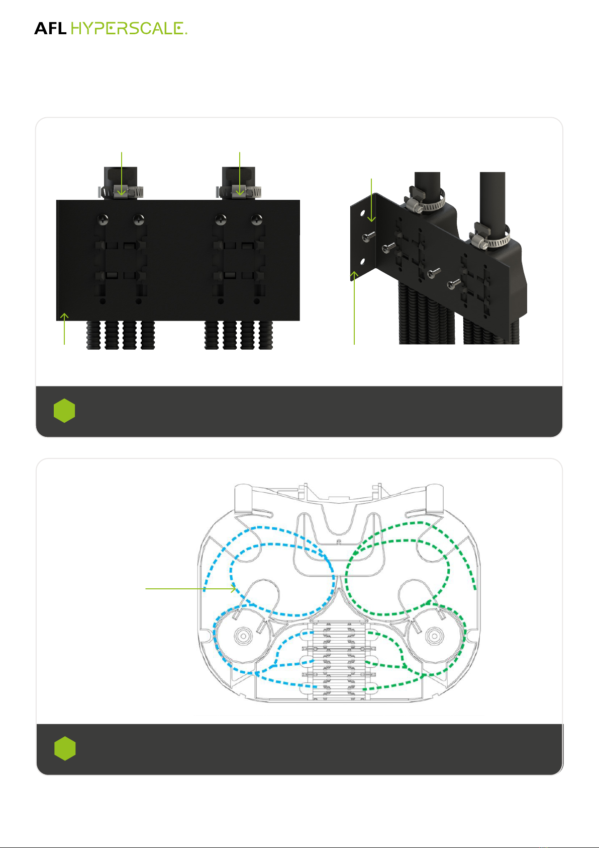
Feeding of Cable
Bottom Feeding Cable Top Feeding Cable
Cable entry point at the bottom of the frame.
1
2
3
Support bracket for the cable SWR Snap
Fit transition box is placed at the lower
mounting position to support bottom
cable feeding. Note: The frame provides
two brackets for a total of four transition
positions.
Corrugate tie-point.
1
2
3
Cable entry point at the top of the frame
through dedicated cable through.
1
2
3
Dedicated through for outbound cable
from the cassette solution to the splice
area.
Support bracket for the cable and SWR
Snap Fit transition box is placed at the
top mounting position to support top
cable feeding. Note: The frame provides
two brackets for a total of four transition
positions.
4
1
2
3
4
1
6
5
6
5
4
4
Fiber slack loop.
5
Cable guard.
Corrugate tie-point.
5
Fiber slack loop.
6
Cable guard.
12 © AFL Hyperscale. All rights reserved
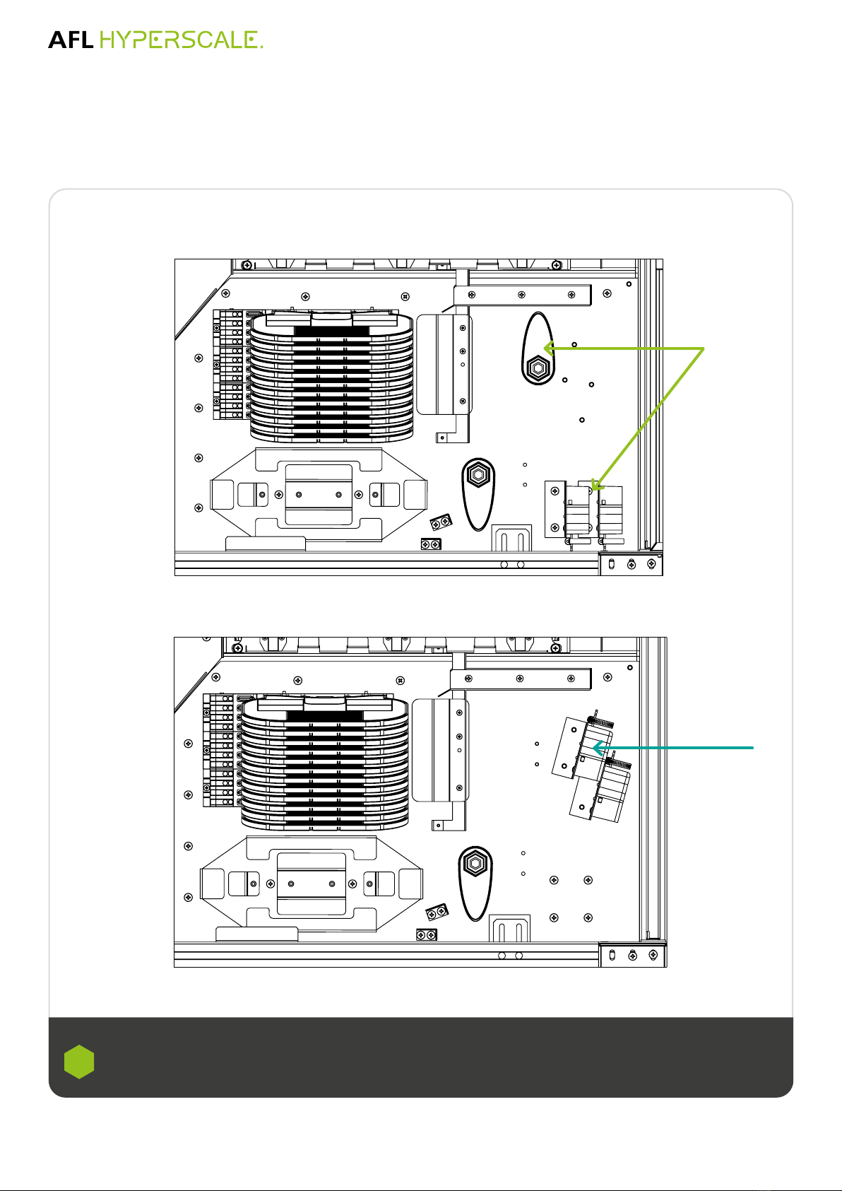
The frame is supplied by default with a bottom feed conguration. To change the conguration to a Top
feeding, the position of the cable landing brackets will need to change, and a spool will need to be removed.
To make the change, proceed to remove and unscrew the two brackets at the bottom and positions as indicated
on the image above. Once done, proceed to remove the spool indicated in the image above.
1
How to change the Conguration for
top/bottom feed
Bottom Feeding
Top Feeding

13
SWR®1200 ODF Installation Guide
© AFL Hyperscale. All rights reserved
Feeding of Ribbon Fiber Cable
• Remove the top cover of the splice area at the bottom of the frame to access the splice tray and cable
support brackets.
• Once the Transition Box is xed on the bottom support bracket, address the corrugate tubing towards
the slack basket and secured the in the corrugate xing point. Proceed to address 1.8 meters of the ber
bundles coming from the corrugate in the ber slack basket
• Proceed to address the remain 1.5 meters of ber bundles into the trays starting from the bottom tray
1a
1b
Bottom Feeding
12th Tray
1st Tray
Slack Basket
24f Cable
from
Cassette
Corrugate
tubing
Corrugate
xing point
Top Feeding
12th Tray
1st Tray
Slack Basket
24f Cable
from
Cassette
Corrugate
tubing

14 © AFL Hyperscale. All rights reserved
Feeding of Ribbon Fiber Cable
Top Feeding
Proceed to adjust the cable guard in the frame located at the top of the frame by releasing the two 2x M4 x 10
screws indicated. This will loose the bracket to allow the incoming cable from the top basket to be safely store
in the frame.
2
Slide hose clamps over cable and strip cable jacket
4m according to manufacturer’s guidelines.
Note: It is commended for top cable feeding to place
the cable in the incoming cable through before
proceeding with the stripping of the cable’s jacket.
Separate out and tape up 144f ber bundle ends
as per splicing schedule and feed into one of the
0.7meter 10mm OD corrugate tubing.
3 4
15
SWR®1200 ODF Installation Guide
© AFL Hyperscale. All rights reserved
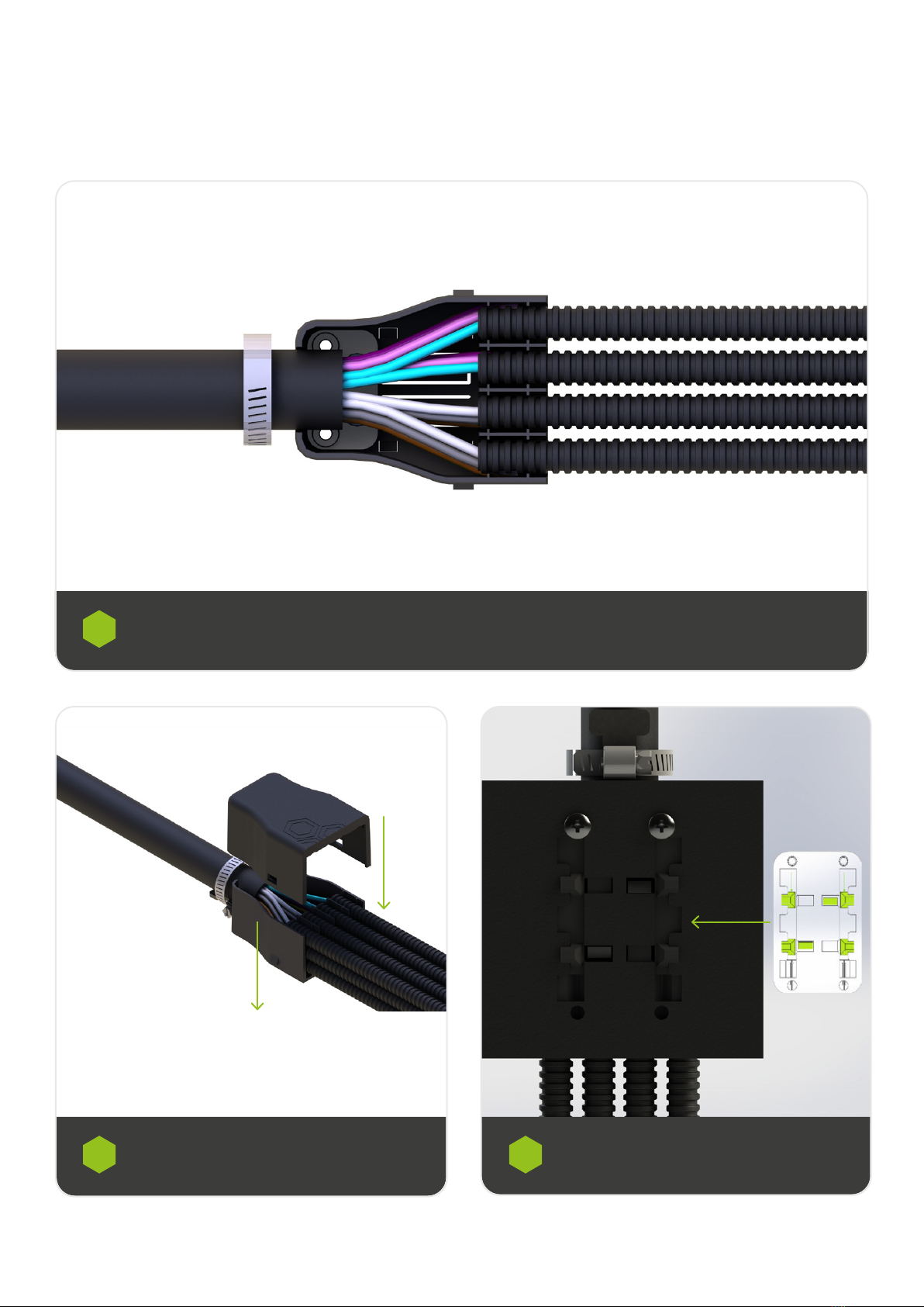
Feeding of Ribbon Fiber Cable
Repeat steps 3-4, ensuring all ber has been placed inside a corrugate tube. Once done, slide the corrugate tubing in the SWR
Snap Fit transition box’s grooves. Proceed to secure the transition on the cable using the hose clamp.
5
3
Attached the lid to the SWR Snap Fit Transition
Box body.
Slide SWR Snap Fit Transition Box onto the bracket
located inside of the splice area of the frame.
6 7
16 © AFL Hyperscale. All rights reserved
Feeding of Ribbon Fiber Cable
Each bracket in the frame provides two positions to secure the SWR Snap-Fit transition Box. Proceed to secure the rst transition
with 2x M4 x 10 screws (position “A”) and second or further expansions on following positions available.
Once the transitions are in installed, proceed to address the corrugate tubing and the bers as it is indicated in steps 1A or 1B
according to the conguration
7
Position A Position B
M4 x 10 Screws
Bracket holder
5 coils, approx., 1.5m
(both 144f ribbon
and 36f single
element)
Bracket holder
Route the incoming/ outgoing ber as per above image -up to 1.5 meters of 144f ribbon per side. Splice according to the splice
schedule.
8

17
SWR®1200 ODF Installation Guide
© AFL Hyperscale. All rights reserved
Installing the U-Series Solution
Housing Installation:
Proceed to identify the required height in the frame. Once done, proceed to press in and tighten the M6 x16 Pozi-head screw
bolt through perforations located at each side of the frame to x the 1RU ber management in place.
1
Fiber Management:
Proceed to press in and tighten the M6 x16 Pozi-head screw bolt through perforations located at each side of the frame to x the
1RU ber management in place.
2
18 © AFL Hyperscale. All rights reserved
Cassette Installation:
Cassettes can be installed or removed from the front of the housing with no tools required.
When the release element is in the unlock position, you can remove/install the cassette by pulling.
4
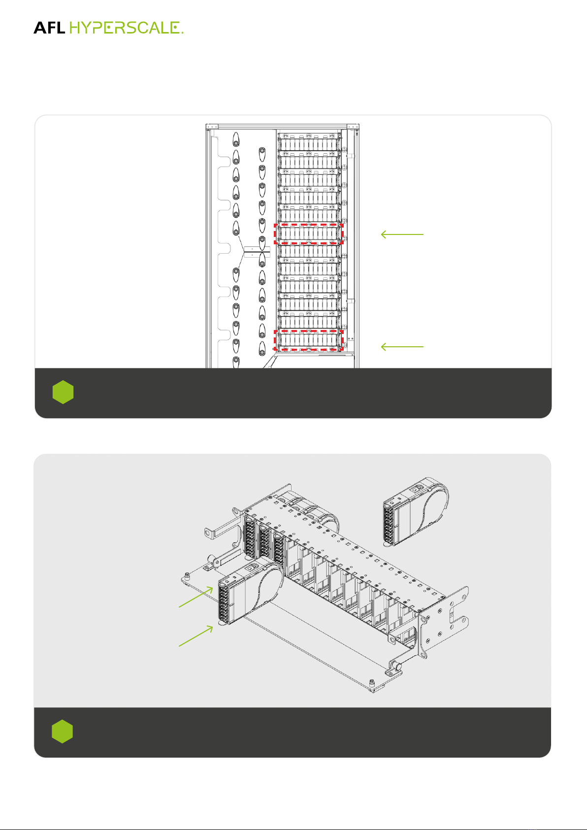
Installing the U-Series Solution
The frame is supplied with am U-series 2RU Hosing installed at positions A1 at the bottom half for External distribution area
and B1 at the top Half for Internal Distribution Area. Additional units for expansion will need to be added on the next available
position, A2 for External Distribution or B2 for Internal Distribution.
3
First position at top
of frame
First housing position for
External Distribution Area
Locking push
latch
B6
B5
B4
B3
B2
B1
A6
A5
A4
A3
A2
A1

19
SWR®1200 ODF Installation Guide
© AFL Hyperscale. All rights reserved
A10 A11 A12
A8 A9
A6 A7
A4 A5
A2 A3A1
The recomened cassette installation used is position one from the bottom housing. It is recommended to instal the cassettes from
left to right.
5
Splice Cassette/Module Installation
in the U-Series 2RU Strat from the
left hand of the housing to right
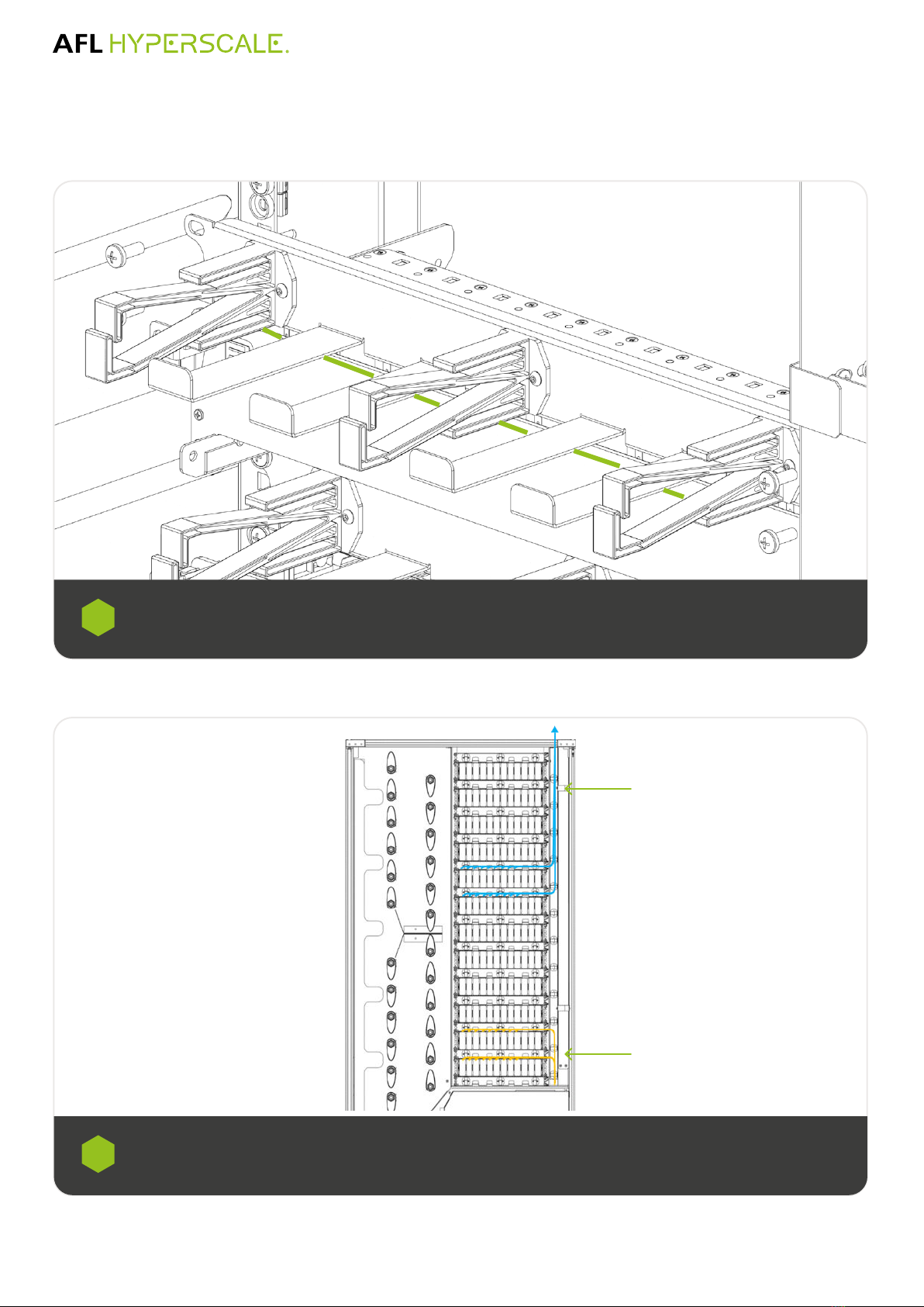
Installing the U-Series Solution
The ber guide is assembled on right-hand side of the rack.
Proceed to lose the xing bolds on the 1RU U-Series Cable Management and slide the ber guide in between the head of the
bolts and the cable manager. Once done tighten the screws one more time
6
20 © AFL Hyperscale. All rights reserved
Cassette Tail Routing
Outgoing ber cable will need to be routed from the top of the cassette into the 1RU U-Series ber management passing
through the bottom hock. Once done the cable will go underneath the nger management of the 1RU U-Series ber
management toward the ber guides located at the right-hand side of the frame to be later route to the splice area.
1
Outgoing ber cables from the cassette presented in the External Distribution are addressed starting from the rst unit from the
top (Position A1) and routed to the splice area in bundles of 6 cables (144f) from the rst six cassette positions. Outgoing ber
cables from the cassette presented in the Internal Distribution Area are addressed starting from the rst unit at the top half and
routed in bundles of 6 cables (144f) from the rst six cassette positions to the cassette designated outside of the frame.
2
Bottom half for External
Distribution Area
Bottom half for Internal
Distribution Area
Table of contents
Other AFL Hyperscale Industrial Equipment manuals


Popular Industrial Equipment manuals by other brands


Siemens
Siemens SIRIUS ACT 3SU19 operating instructions

Unitary products group
Unitary products group PT8 installation manual

Masterbuilt
Masterbuilt HITCH-HAUL HDMF Operation manual & safety instructions

Draco
Draco K5 manual

Siemens
Siemens SIMOVERT MASTERDRIVES 6SE70 C.87-2DA0 Series operating instructions

Ceriotti
Ceriotti C3000 Assembly instructions