Enviro Energy Solutions EBGL Series User manual

ÿÿÿÿÿÿÿÿÿ ÿÿÿÿÿÿÿÿÿÿÿÿÿÿ
EBGL SERIES VERTICAL TANKS
WITH FIXED COIL HEAT EXCHANGERS
TECHNICAL MANUAL

Before the installation and use of an ENVIROENERGY SOLUTIONS Solar Tank, Buffer Tank, Heat Pump Tank or
electric Calorifier please read and observe carefully all the instructions concerning the installation,
maintenance and use of the product, in this manual. The non-observance of these instructions may result in
the cancelation of the warranty.
GENERAL SAFETY INSTRUCTIONS
•Attention when lifting the tank and always take precautions in order to avoid possible accidents, injuries
and other hazards. During transportation and handling of the tank avoid abrupt movements as they may
result in fall and damaging of the Tanks. To avoid damaging the tank, do not remove the packaging, until
it reaches the installation location.
•All installations and maintenance must be performed by qualified and certified professionals, following
all relevant local norms and regulations (1), industry codes, and according to the manufacturer’s
instructions.
•Always make sure that the installation site, especially on roof tops, is adapted to the weight and
mechanical restraints of Tank when full (and eventually a 30% margin), as well as any further weight
expected (snow, rain, etc...). ENVIROENERGY SOLUTIONS declines any responsibility that may arise from
an improper or defective installation or from incorrect manipulation of the system or accessories
composing it.
•Always make sure there is enough space around the Tank for maintenance purposes, as well as for the
electric cabling and plumbing. It is recommended to agree with the client for the location of the
installation and the routing of pipes and cabling.
•In case the Tank is placed Outdoors in regions with heavy snow fall or strong winds, it may be necessary
to further anchor the system to the point of installation. In this case it is up to the installer along with
the client to determine the best and safe way to install the Tank. Additional fixing points or equipment
may be required.
•Never fill the closed circuit or connect the electric element with an empty tank. The tank must always
be filled with water during these operations due to a risk of severe damage to the Tank.
•Before starting the installation or maintenance, the main power supply to the system must always be
turned OFF, and the Heat Exchangers in case of Removable Heat Exchangers, must be removed.
•Improper installation and works can contaminate the potable water. Install the Tank hygienically and
rinse the Tanks and piping thoroughly with potable water
•Install and use potable water pipes according to current standards and local norms and regulations.
•The use of plastic, PVC or polypropylene piping is not recommended, especially for the closed circuit, due
to the very high temperatures developed by the installations. In any case, make sure that all the piping
used in contact or close to the systems outlets can withstand minimum temperatures of 100ºC, or 180ºC
if in contact with the primary (closed) circuit.
ENVIROENERGY SOLUTIONS recommends the use of copper or stainless-steel piping for safer and higher
performance.
•It is recommended that the Tanks be maintained by a professional, checked and cleaned at least every 2
years. In locations with hard or dirty water an annual maintenance and cleaning is recommended. Please
refer to the “Maintenance and Servicing” section of this manual.
•A pressure release and safety valve is mandatory on the cold-water inlet of the tank and a pressure
reducing valve is mandatory in case the pressure of the water coming into the tank is above 3 bar.
•A mixing valve is compulsory on the hot water outlet in order to limit risks of burning and Expansion
Vessels are recommended in order to limit pressures in the Tank and unnecessary loss of Water.

GENERAL INSTALLATION INSTRUCTIONS
•Always make sure that all the piping of the primary and secondary circuits, going to and coming from the
Tank, are very well insulated, even in hot climate regions and treated for UV radiation.
•Avoid leaving the Tanks for long periods without using hot water (holidays, prolonged absences, etc...) due
to risks of overheating, or make sure all the heating sources (solar panels, heat pumps, electric elements,
burners, etc…) are turned off or inactive during this period.
•In case of use of Electric Heating Elements, the Tanks must be grounded
•It is recommended that the installation location be equipped with functional drainage on the floor
•Hydraulic connections to the tank must be such as to limit the phenomenon of electrolysis
•Every service and maintenance should be recorded in the maintenance book. This record is a key element to
the validity of the warranty and should be made available on request
•Under no circumstances should any welding or repairing be made on the tank’s metal structure. Risk of
deterioration or destruction of the tank and annulation of the warranty.
•The electric heating element is not part of the system but an additional part and it should be installed by a
certified electrician. The electric back-up should be used only in case the water temperature in the Tank is
under 50°C. The constant and unreasonable use of the electric back-up may cause damage to the tank and
cause annulation of the warranty.
•The quality of the water entering the Tanks should be within potable standards and in any case be within the
values of the table below. If the quality of the water does not correspond to these values then special filters
and water softeners may need to be installed to satisfy these conditions, or the warranty will not be valid.
WATER QUALITY REQUIRMENTS
Specification
ph
Total Hardness
Chlorides
Free Chlorine
Conductivity
TDS
Value
7-9
<100 mg/1
<0,5 mg/lt
<80 mg/lt
<650 mS/cm 25°C
<600 mg/lt
WARNING:
IF THE HOT WATER SYSTEM IS NOT USED FOR TWO WEEKS OR MORE, A QUANTITY OF HIGHLY FLAMMABLE
HYDROGEN GAS MAY BE ACCUMULATED IN THE WATER HEATER. TO DISSIPATE THIS GAS SAFELY, IT IS
RECOMMENDED THAT A HOT TAP BE TURNED ON FOR SEVERAL MINUTES UNTIL DISCHARGE OF GAS CEASES.
USE A SINK, BASIN, OR BATH OUTLET, BUT NOT A DISHWASHER, CLOTHES WASHER OR OTHER APPLIANCE.
DURING THE PROCEDURE THERE MUST BE NO SMOKING, OPEN FLAME OR ANY ELECTRICAL APPLIANCE
OPERATING NEARBY. IF HYDROGEN IS DISCHARGED THROUGH THE TAP, IT WILL PROBABLY MAKE AN UNUSUAL
SOUND AS WITH AIR ESCAPING.
•The safety of the Tanks and validity of the warranty are conditioned by the use of genuine ENVIROENERGY
SOLUTIONS spare parts and accessories. Please only use genuine ENVIROENERGY spare parts and accessories
from your nearest ENVIROENERGY SOLUTIONS dealer or contact the manufacturer.
ENVIROENERGY SOLUTIONS declines any responsibility that may arise from the non-observance of the
installation, maintenance and use instructions herein, non-observance of relevant local norms, regulations
and industry codes, improper or defective installation, or incorrect manipulation of the system or the
accessories composing it.
TECHNICAL SPECIFICATIONS
A. GENERAL CHARACTERISTICS
•Internal Tank Material: Steel
•Welding Type: Automatic
•Internal Tank Protection: Alimentary Quality Glass Enamel
•Anodic Protection: 2 Magnesium Rods, One on Each Flange
•Maximum Operating Pressure: 10 bar
•Water Test Pressure: 15 bar
•Maximum Operating Temperature: 95°C
•Insulation: Polyurethane foam
➢For Tanks up to 300lt: Hard Polyurethane Foam, 60mm, Density 52kg/m3
➢For Tanks above 500lt: Soft Polyurethane Foam 80mm and 100mm
•Heat Exchanger: Fixed Coil from Steel Tube 1’’ - Glass enameled
•Maximum Coil Operating Pressure: 16 bar
•Maximum Coil Test Pressure: 25 bar
•Maximum Coil Operating Temperature: 130°C
•Electric Heater: Optional, Power Output Upon Request
•External Cover: Metallic or Soft PVC (color upon request)
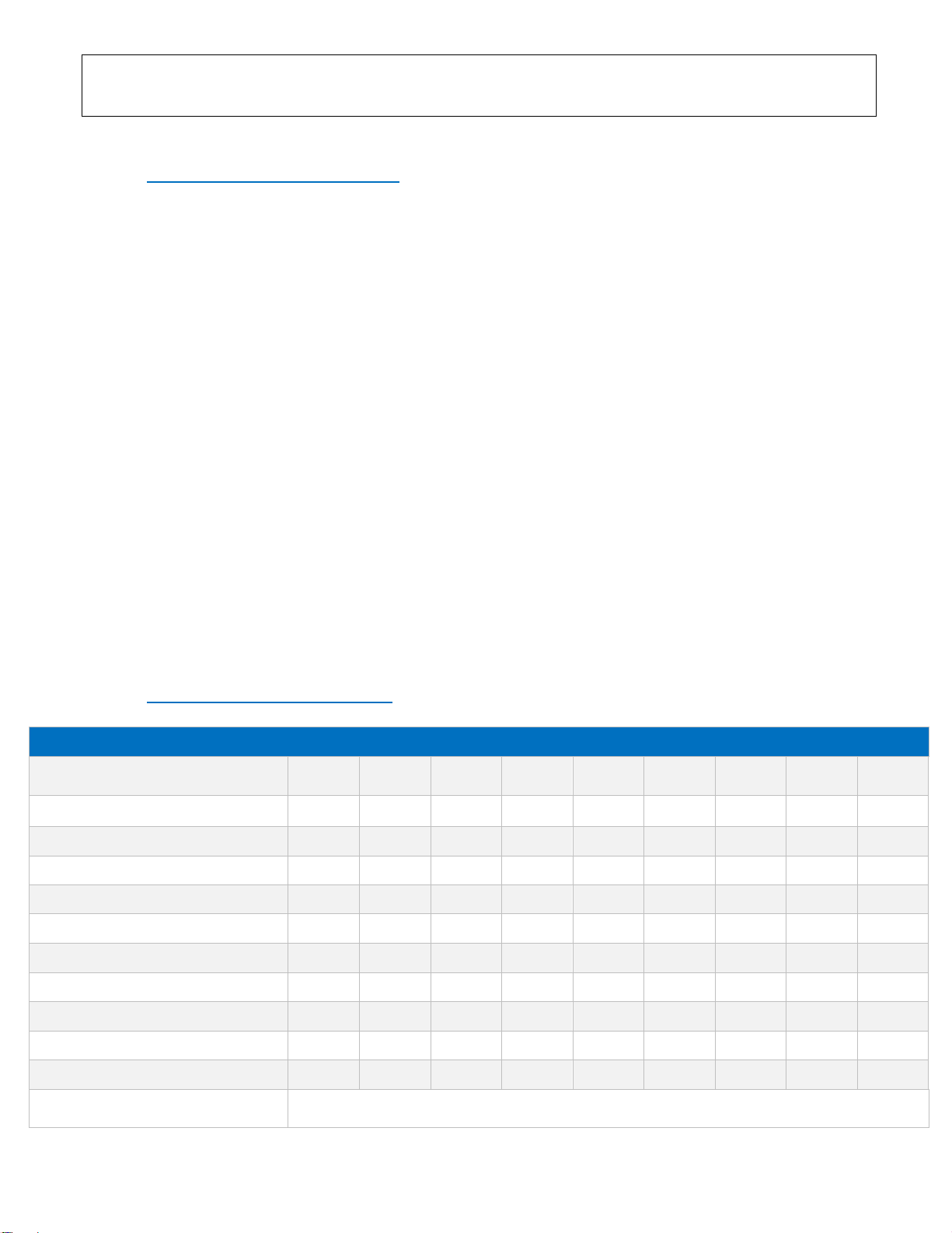
B. SPECIFIC CHARACTERISTICS
EBGL SERIES TANKS GENERAL SPECIFICATIONS
Model
EBGL
160
EBGL
200
EBGL
300
EBGL
500
EBGL
800
EBGL
1000
EBGL
1500
EBGL
2000
EBGL
3000
Nominal Volume (Lt)
160
200
300
500
800
1000
1500
2000
3000
Internal Tank Body Thickness (mm)
2,5
2,5
2,5
3
4
4
5
5
6
Insulation Type
Hard PU
Hard PU
Hard PU
Soft PU
Soft PU
Soft PU
Soft PU
Soft PU
Soft PU
Insulation Thickness (mm)
60
60
60
100
100
100
80
80
80
Insulation Density (kg/m2)
52
52
52
25
25
25
25
25
25
Lower Flange Ø (mm)
140
140
140
193
193
193
140
140
140
Upper Flange Ø (mm)
140
140
140
196
196
196
---
---
---
Lower Flange Anode Ø (mm)
Ø22x300
Ø22x300
Ø22x500
Ø32x500
Ø32x500
Ø32x500
---
---
---
Upper Flange Anode Ø (mm)
Ø22x500
Ø22x500
Ø22x500
Ø32x500
Ø32x500
Ø32x500
Ø32x500
Ø32x500
Ø32x500
Energy Class
C
C
C
C
C
C
C
C
C
Electric Back-up Heating Element
(EH1 and EH2)
Optional –Power Output Upon Request

C. HEAT EXCHANGER CHARACTERISTICS
•Heat Exchanger Efficiencies for DHW Heating from 15°C to 60°C for Tanks up to 1000lt
•Heat Exchanger Efficiencies for DHW Heating from 10°C to 60°C for Tanks from 1500lt to 3000lt
•Heat Exchanger Inlet Temperatures 80°C
EBGL SERIES TANKS WEIGHT AND VOLUMES DEPENDING ON NUMBER OF HEAT EXCHANGERS
Model
EBGL
160
EBGL
200
EBGL
300
EBGL
500
EBGL
800
EBGL
1000
EBGL
1500
EBGL
2000
EBGL
3000
Nominal Volume (Lt)
160
200
300
500
800
1000
1500
2000
3000
Actual Volume for Tanks Without
Heat Exchangers (Lt)
170
212
320
520
830
1040
1493
1846
2808
Total Weight for Tanks Without Heat
Exchangers (kg)
53
58
87
117
170
195
305
501
665
Actual Volume for Tanks With 1 Heat
Exchanger (Lt)
165
204
313
505
817
1023
1461
1802
2749
Total Weight for Tanks With 1 Heat
Exchanger (kg)
65
73
110
147
215
245
380
594
840
Actual Volume for Tanks With 2 Heat
Exchangers (Lt)
160
196
300
497
800
998
1446
1778
2717
Total Weight for Tanks With 2 Heat
Exchangers (kg)
75
85
125
165
240
275
417
640
925
Internal Tank Diameter Ø (d) (mm)
480
480
510
650
850
850
960
1100
1300
External Tank Diameter Ø (D) (mm)
600
600
630
850
1050
1050
1120
1260
1460
Total Height (H) (mm)
1070
1460
1800
1800
1800
2000
2300
2230
2560
Tilt Height (mm)
1227
1579
1907
1991
2084
2259
2559
2562
2947
EBGL SERIES TANKS HEAT EXCHANGER SPECIFICATIONS AND EFFICIENCY
Model
EBGL
160
EBGL
200
EBGL
300
EBGL
500
EBGL
800
EBGL
1000
EBGL
1500
EBGL
2000
EBGL
3000
Max. Coil Operation Temperature (°C)
130
130
130
130
130
130
100
100
100
Max. Coil Operation Pressure (bar)
16
16
16
16
16
16
25
25
25
Lower Coil Surface (m2)
0,80
1,00
1,55
1,95
2,36
2,99
3,86
4,65
7.20
Upper Coil Surface (m2)
0,55
0,80
1,00
1,23
1,33
1,99
1,86
2,26
3,50
Lower Coil Volume (Lt)
5,10
6,50
10,00
12,40
14,90
19,10
27,50
34,50
47,00
Upper Coil Volume (Lt)
3,10
5,10
6,40
7,80
8,40
12,70
11,00
17,00
23,00
Lower Coil Diameter (in)
1’’
1’’
1’’
1’’
1’’
1’’
1’’
1’’
1’’
Upper Coil Diameter (in)
1’’
1’’
1’’
1’’
1’’
1’’
1’’
1’’
1’’
Lower Coil Efficiency (Lt)
kWh
13,10
14,40
22,90
25,80
30,15
38,50
95,30
107,00
127,90
lt/h
900
900
900
900
900
900
1640
1840
2200
Upper Coil Efficiency (Lt)
kWh
10,40
13,60
16,40
19,20
20,50
25,50
57
65,10
71,50
lt/h
900
900
900
900
900
900
980
1120
1230
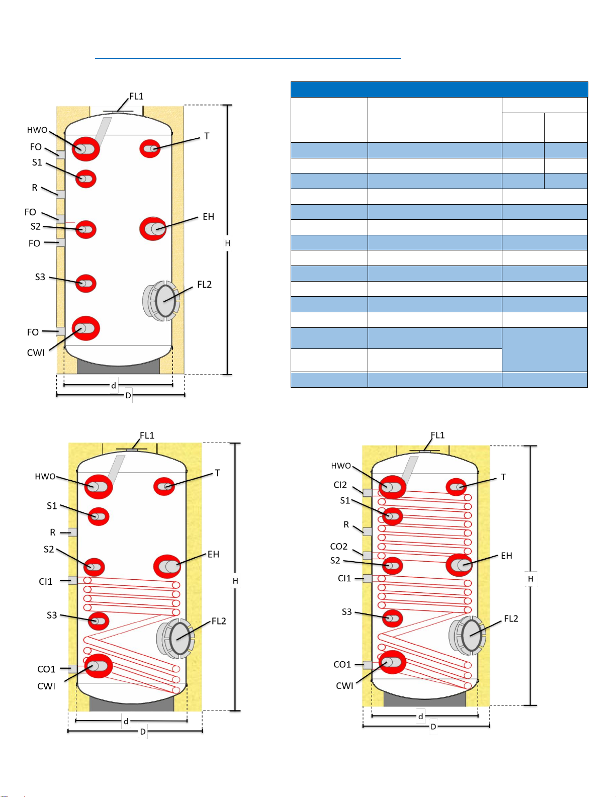
D. SCHEMATIC DRAWINGS FOR TANKS 160Lt TO 1000Lt
LEGEND
Abbreviation
Explanation
Diameter
160lt-
500lt
800lt-
1000lt
CWI
Cold Water Inlet
1’’
1½’’
HWO
Hot Water Outlet
1’’
1½’’
R
Recirculation
1’’
1½’’
CI1
Lower Coil Inlet
1’’
CO1
Lower Coil Outlet
1’’
CI2
Upper Coil Inlet
1’’
CO2
Upper Coil Outlet
1’’
EH
Electric Heating Element
1½’’
S1
Sensor 1
½’’
S2
Sensor 2
½’’
S3
Sensor 3
½’’
T
Thermostat
½’’
FL1
Upper Flange
As per Gen.
Specifications
Table p.4
FL2
Lower Flange
FO
Free Outlet
1’’

E. SCHEMATIC DRAWINGS FOR TANKS 1500Lt TO 3000Lt
LEGEND
Abbreviation
Explanation
Diameter
1500lt-2000lt
3000lt
CWI
Cold Water Inlet
1¼’’
1½’’
HWO
Hot Water Outlet
1¼’’
1½’’
R
Recirculation
1¼’’
1½’’
CI1
Lower Coil Inlet
1¼’’
1½’’
CO1
Lower Coil Outlet
1¼’’
1½’’
CI2
Upper Coil Inlet
1¼’’
1½’’
CO2
Upper Coil Outlet
1¼’’
1½’’
EH
Electric Heating Element
1½’’
S1
Sensor 1
½’’
S2
Sensor 2
½’’
S3
Sensor 3
½’’
T
Thermostat
½’’
A
Anode
Ø32x500
FL
Lower Flange
5’’

MAINTENANCE AND TROUBLESHOOTING
A. MAINTENANCE AND SERVICING OF THE TANKS
1. General maintenance
In order to ensure the constant well-functioning of the Tanks, they must be reviewed and maintained periodically
(see warranty sheet) and the warranty sheet accompanying must be completed accordingly by the installer.
All installations and maintenance must be performed by qualified and certified professionals, following all
relevant local norms and regulations (1), industry codes, and according to the manufacturer’s instructions.
Before starting any maintenance work, the main power supply to the system must always be turned OFF, and
the Heat Exchangers in case of Removable Heat Exchangers, must be removed.
Revisions consists of:
➢The optical and physical inspection of the tightness of all joints and connections (hydraulic and electrical),
verification that all safety valves, pressure reducing valves and mixing valves are working properly (safety
valves on primary and secondary circuit), that the insulation of all the pipes is in good condition.
➢Making sure that scale and salts have not accumulated in the valves or in the Tank. Poor water quality at
the water can result in scale formation and may block the safety valves and Tank outlets leaving the tank
unprotected against very high temperatures above 90°C and high pressure (greater than 10 bars).
➢Making sure the electrical heating elements and thermostats are working properly and do not have scale
or salts accumulation.
➢Cleaning of the Tanks and removal of scale or deposits inside the Tanks, on the Heat Exchangers and on
the electric elements, valves, etc…
➢Making sure that the Heat exchanger is in good conditions and perfect working order
➢The anode (magnesium rod) must be checked every year and replaced if it has been worn-out or
reduced to 50% of its initial size or weight or if it has been covered by the accumulation of salts.
➢Verifying that the weight of the thermal fluid in the primary circuit is adapted to local climatic
conditions. The thermal fluid must in any case be changed at least every 3 years as it loses its
properties through time.
➢Verifying that the water quality entering the Tank is within standards as per the requirements in the table
in the General Installation Instructions in this manual and the eventual filters and water softeners are in
proper working order.
Attention: do not use any detergents, acids or any other corrosive products that may damage the enamel lining
of the Tanks.

2. Replacing the sacrificial anodes (magnesium rods)
For optimal protection of the system against electrolysis, all ENVIROENERGY SOLUTIONS tanks include
magnesium rods (sacrificial anodes) which must be checked and replaced if necessary, at least every year
depending on the quality of the water. The size of the anode varies depending on local norms and requirements.
For replacing the anode, proceed as follows:
•Shut down the main power supply
•Remove the safety valves or expansion vessel.
•Empty the tank.
•Remove the protective cover of the flange and Heat exchanger.
•Pull out the thermostat with caution.
•Remove the flange and unscrew the anode. Screw-on a new anode and following the same procedure
backwards prepare and set the system back to work.
B. TROUBLESHOOTING
In case the Solar Water Heater does not produce enough hot water, please verify the following:
1. That all hydraulic connections of the system are water tight and there are no leaks.
2. That there are no leaks on the taps or on the piping of the building
3. That the heating sources are working properly.
4. If the level of the thermal fluid in the closed circuit is not too low. Set to level filling with thermal fluid
mixture through the fluid inlet where the safety valve or expansion vessel is placed.
5. That the pipes connecting the heating source to the tank are not bent twisted nor have any angles.
6. That there is no air trapped in the closed circuit of the system.
7. That the supply of cold and hot water is connected.
8. That the temperature set on the mixing valve is not too low (below 50ºC depending on local regulations)
9. If the electric back-up is working. In case it is not working please check the following:
•That the main power supply is ON
•That the thermostat is not set too low
•That the back-up element is not on security mode. The security button must be pushed-in
•That the thermostat and back-up element are not damaged
•That the back-up element wiring is properly connected and to the relevant terminals
If problems persist, then please consider:
a) That the weather conditions allow the proper heating of the system
b) The hot water consumption does not exceed the installation’s capacity, or the consumers’ expectations
of are not above this capacity.
c) The consumer has understood the use of the electrical back-up
Note: all verifications and interventions must be carried out by qualified and certified personnel.
1. The present warranty covers the repair or substitution of the defective parts or part
of the products from authorised personnel. The replacement of the complete product
can only happen if the repair is not possible. In any case of failure or malfunction of
the product, the buyer must immediately inform the company as well as the
distributor.
2. The present warranty covers only the supply of spare parts and in any case does not
cover any expenses for shipping costs. Dispatch costs as well as any authorized
personnel expenses or expenses for replacement of the defective parts are on clients
charge.
3. In case of malfunction, the dispatch of the defective parts/products to the company
headquarters or place of repair of the defective product is on clients charge.
Otherwise, all costs for on-spot repair from authorised personnel at the client’s
location is at client’s expense. The company reserves the right of decision on the type
and how the repair will be made according to its judgment. Every repair crew visit,
even for just auditing and checking the system is charged with the expenses and fees
of the technician.
4. Any warranty claim can only be valid if this original warranty card is presented
accompanied with the original purchase receipt edited by the distributor and the
Maintenance Book. Furthermore, for the warranty to be valid the buyer must
complete and sign both parts of the warranty (clients copy and distributors copy) and
send the relative parts to the parties intended within 10 days from the date of
installation.
5. All spare parts or parts repaired or replaced have the same benefit of warranty period
as the remaining period of the general warranty of the system.
6. The electric parts of the system (electric element, thermostat, etc…) carry only two
(2) years warranty from the date of purchase.
7. The warranty does not cover the anode (magnesium rod) or its replacement
8. The manufacturer assumes no responsibility and the present warranty is invalid in the following cases:
A. When the product has not been checked, repaired, altered or installed by non-authorized personnel
by the manufacturer or the distributor –or his partners
B. If the ordinary services of the product have not been performed by authorised by the company
personnel and as per Maintenance Recommendations in the product Installation Manual. The 1st service
must be conducted within 1 year (12 months) after the date of purchase of the product at the clients care
and expense. Proof of service is the signature and stamp of the authorised personnel at the bottom of
the present warranty card in combination with the original invoice of the service from the service
technician.
C. When any damage or malfunction is done to people or thing or the product itself due to accident,
mishandling, improper or inappropriate use (intentional or unintentional), negligence, maltreatment or
bad installation of the product, lack of servicing of the product, wrong technical intervention on the
product or its parts, or to wrong connexions –cabling of the electrical resistance or other electrical parts,
other the instructions provides by the manufacturer.
D. If damage or malfunction of the system is due to bad weather conditions and natural disasters or
vandalism (such as: natural disaster, frost, storms, floods, hail, earthquakes, fires, arson, etc…)
E. Damage to the heating element of the tank or the Tank itself due to excessive salt, scale, dirt or other
external bodies concentration. Damage of the tank caused by overheating or excessive pressure of the
water supply network or generally by extreme operating conditions and extrinsic factors. Damage due to
lack of safety equipment installation to protect the Tank or people (such as safety valves, mixing valves,
pressure reducing valves, etc…). Damage caused by improper maintenance, or unauthorized third-party
intervention.
F. In case of normal wear and deterioration (due to time, etc…) of the external parts of the product
which do not affect the proper use of the system, or in case of damage to any valves (safety valves, mixing
valves, pressure reducing valves, etc…). Or in case water standards do not correspond to the standards
and values as these are specified in this manual.
9. Manufacturer retains the right of control of the validity of the warranty at each stage of product repair and
to charge the owner for the costs of the repairs (value of the parts included) in this case the conditions
described in detail in the present warranty card are not met.
10. The present warranty does not affect the owner's and consumer’s rights, as these are foreseen by Cypriot
law.
WARRANTY CONDITIONS
DATE STAMP AND SIGNITURE OF MAINTENANCE PERSON
1st 2nd 3rd 4th 5th 6th 7th 8th

This manual suits for next models
9
Table of contents
Popular Industrial Equipment manuals by other brands

Meritor
Meritor MORH2P035 Series quick start guide

Spirax Sarco
Spirax Sarco FV6 Installation and maintenance instructions

Group Dynamics
Group Dynamics 2300 Technical manual

Warner Electric
Warner Electric PB-500 Pin Drive installation instructions

Bosch
Bosch FDP 0001 A installation guide

Festo
Festo MS6-SP Assembly instructions

Sealey
Sealey Quality Machinery HPT750.V2 instructions

Grizzly
Grizzly T32839 instructions

AquaStar
AquaStar FLOW STAR SKRFL12 Series Installation and user guide

ASO Safety Solutions
ASO Safety Solutions SENTIR mat instruction manual

Graco
Graco LineLazer III 200HS Operation

Siemens
Siemens RM400 C Series operating manual


