3
SENTIR mat 14
SENTIR mat 14 ARB (SENTIR mat 14 TBV)
3
3
,5
(1,3
2
")
6
(0
,2
4")
5
(0
,2
0
")
6
7
(2
,6
4")
17,8 (0,70")
7
,5
(0
,3
0
")
5
(0
,2
0
")
40 (1,57")
17,8
(0
,70")
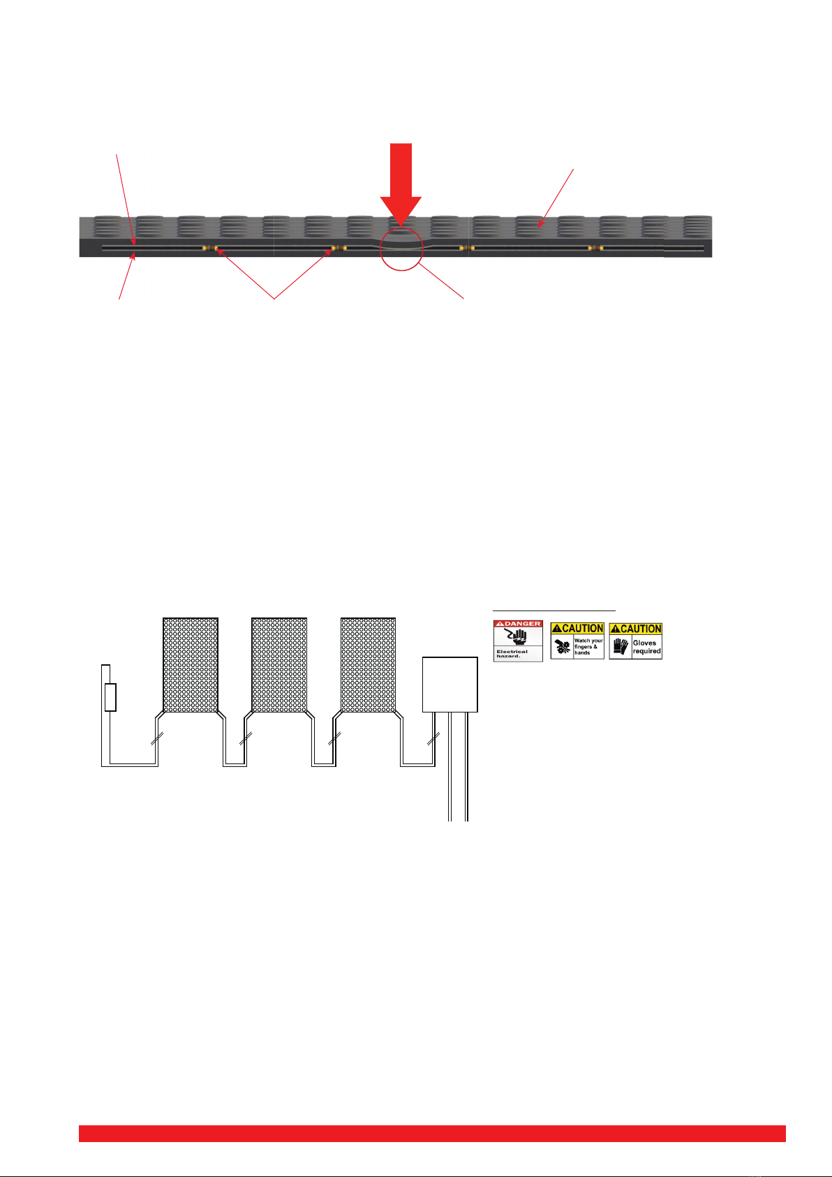
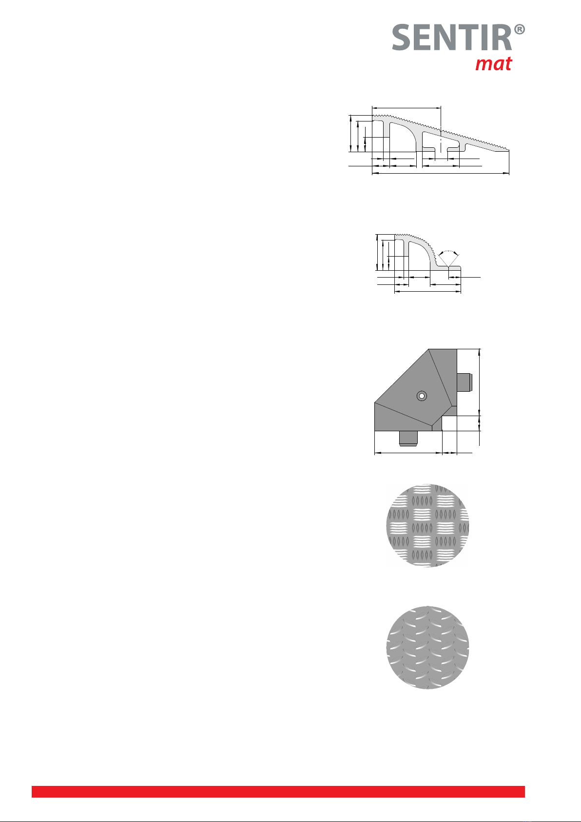
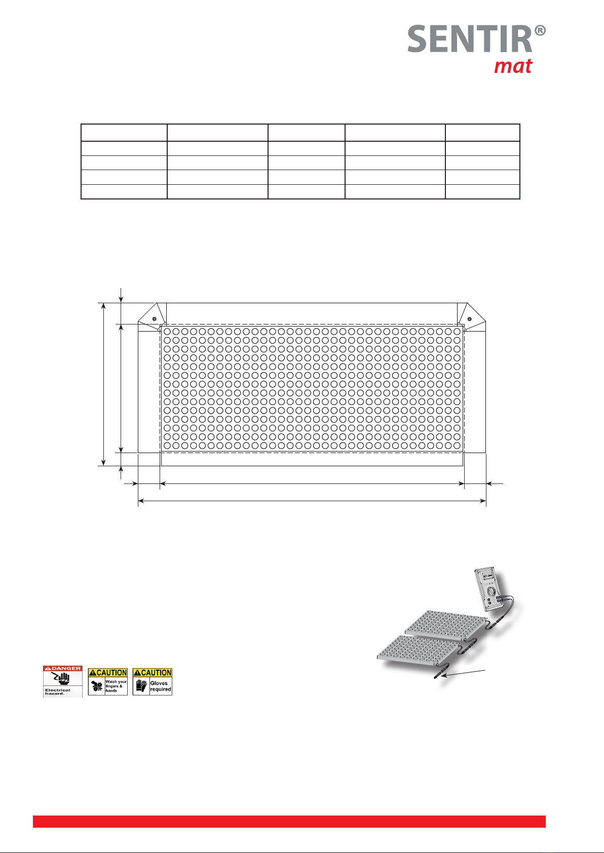
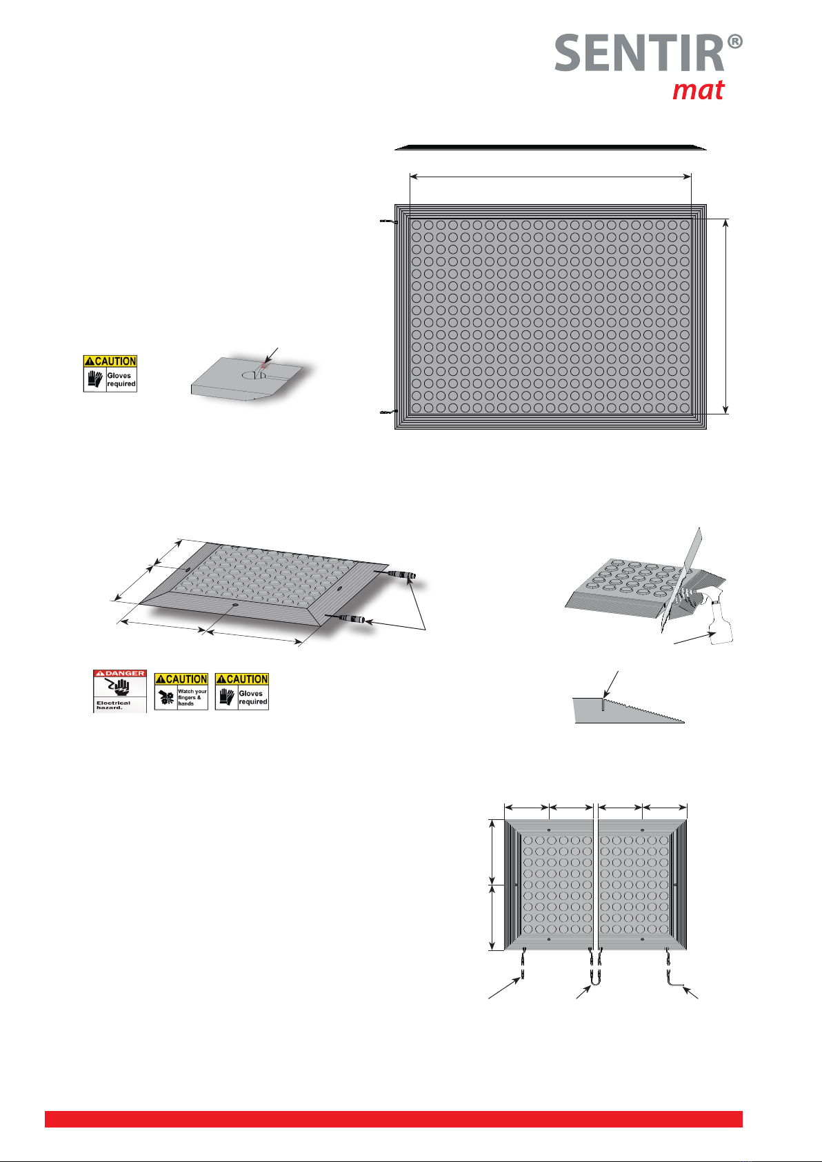
Ramp rail RS 14
Marking groove Fixation rail BS 14
Cable duct Connection cable Fastening grommet (available on request)
33,5 (1,32")
6 (0,24")
5 (0,20")
67 (2,64")
17,8 (0,70")
7,5 (0,30")
5 (0,20")
40 (1,57")
17,8 (0,70")
14,5 (0,57")
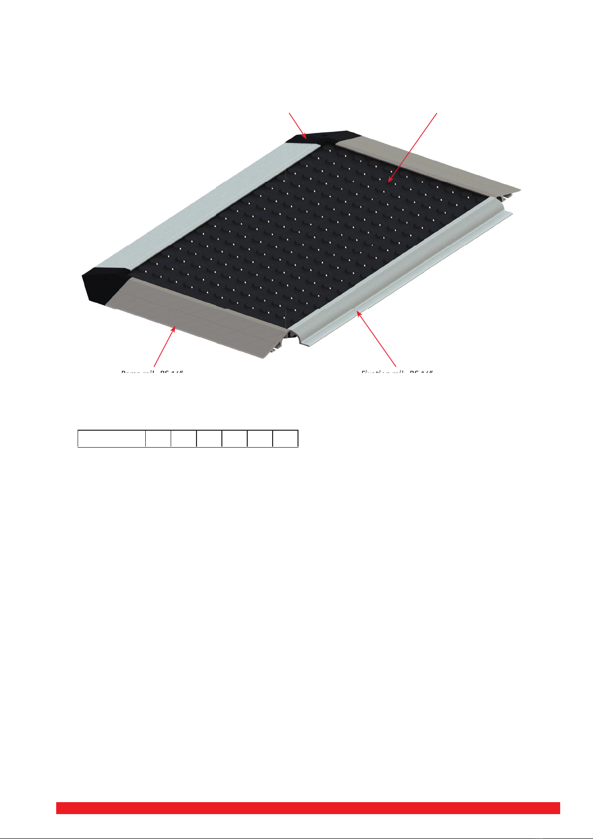
Ramp rail RS 14
Marking groove Fixation rail BS 14
Cable duct Connection cable
Steel plate
Technical specication for Safety contact mats
SENTIR mat 14 U/ SENTIR mat 14 T SENTIR mat 14 ARB
Max. dimensions 2000 mm x 1250 mm (78,74“x49,21“) 2000 mm x 1250 mm (78,74“x49,21“)
Standard dimensions
available from stock
only SENTIR mat 14 U / T
1000 mm x 750 mm (39,37“ x 29,53“)
1000 mm x 1000 mm (39,37“ x 39,37“)
1000 mm x 1500 mm (39,37“ x 59,06“)
Height 14 mm (0,55“) with covering 14 mm (0,55“) with covering
Surface Euro dot checkered
Weight U 24,9 Kg/m2(54,9lb/10,76ft2);
T 26 Kg/m2(57,32lb/10,76ft2)
approx. 31,5 kg/m² (69,45lb/10,76ft2)
Inactive edge 16 mm(0,63“) 30/40 mm (1,18“/1,57“)
Switching pressure Test piece Ø 80 mm (3,15“) = approx. 150 N Test piece Ø 80 mm (3,15“) = approx. 150 N
Static load max. 2000 N over Ø 80 mm (3,15“) * max. 2000 N over Ø 80 mm (3,15“) *
Response time < 25 ms* < 25 ms*
Switching cycles min. 1 million* min. 1 million*
Electrical capacity 24 V 100 mA 24 V 100 mA
Material PUR black, 78 +/- 5 Shore A
(optional PUR yellow, 78 +/- 5 Shore A)
PUR black, 78 +/- 5 Shore A
(optional PUR yellow, 78 +/- 5 Shore A)
Protection class IP 65 (IP 67) IP 65 (IP 67)
Temperature range -10°C (+14°F) to +55°C (+131°F) -20°C (-4°F) to +55°C (+131°F)
Chem. resistance:
Oil
Petrol
Solvent
Diluted Acid
Diluted lye
good
resistant
sufcient
resistant
resistant
Aluminium
good
good
good
good
good
Connection cable Standard: 2 pcs. - 2 x 0,34 PVC / PU cover black Ø 3,5 mm with
M8 male/female plug 120 mm (4,72”)
Alternative: 1 pc. 4 x 0,25 PVC / PU cover black Ø 4,4 mm with open wires
(BN: 1, BU: 3 || WH: 2, BK: 4)
Fire and shock evaluation UL 508 and CSA C22.2 no. 14 (no evaluation of protective safety function)
* tested according to DIN EN ISO 13856-1