Environics 4000 Series User manual


II
COPYRIGHT
© 2017 Environics Inc. All Rights Reserved. This manual and the software
contained within the product(s) described are copyrighted with all rights reserved.
TRADEMARKS
Environics is a registered trademark of Environics Inc. All other brand names,
company names and product names mentioned are the property of their
respective owners.
Neither Environics nor any of its employees shall be liable for any direct, indirect,
special, incidental or consequential damages arising out of the use of its
instruments and software even if Environics has been advised in advance of the
possibility of such damages. Such excluded damages shall include, but are not
limited to: costs of removal and installation, losses sustained as the result of
injury to any person or damage to property.
Environics Inc.
69 Industrial Park Road East
Tolland, CT 06084-2805 U.S.A.
Phone: (860) 872-1111 Fax: (860) 870-9333
E-mail: INFO@ENVIRONICS.COM Web: HTTP://WWW.ENVIRONICS.COM

III
TABLE OF CONTENTS
INTRODUCTION 4
SETUP AND CONFIGURATION 5
HARDWARE SETUP 5
SOFTWARE SETUP 6
BASIC CONFIGURATION 8
GAS LIBRARY CONFIGURATION 8
CYLINDER LIBRARY CONFIGURATION 10
CYLINDER AUDITING 13
MANAGING PROFILES 14
RUNNING THE INSTRUMENT 16
CONCENTRATION MODE OVERVIEW 16
CONFIGURING CONCENTRATION MODE 17
RUNNING CONCENTRATION MODE 20
FLOW MODE OVERVIEW 21
CONFIGURING FLOW MODE 21
RUNNING FLOW MODES 24
DIVIDER MODE OVERVIEW 25
CONFIGURING DIVIDER MODES 25
RUNNING DIVIDER MODES 29
PROGRAM MODE OVERVIEW 30
CONFIGURING PROGRAM MODES 30
RUNNING PROGRAM MODES 32
SCHEDULE MODE OVERVIEW 33
CONFIGURING SCHEDULE MODES 33
RUNNING SCHEDULE MODES 36
ADMINISTRATION 37
RESTRICTING USER ACCESS 37
RESETTING A USER PASSWORD 38
REPORTS/LOGGING 39
MANAGING REPORTS 40
INSTRUMENTS MENU 42
INSTRUMENT CONFIGURATION 42
CALIBRATION 43

INTRODUCTION
4
INTRODUCTION
The Environics Series 4000 Gas Mixing System and the Environics Series 4040
Gas Dilution System are operated using the Environics software. This software is
installed on a PC, and provides user friendly control of all primary functions. The
software communicates with the Environics systems via a serial or USB
interface.
The Environics Series 4000/4040 Software is a 32 bit Windows application,
designed to run on Windows 7/8/10 PC. The minimum PC specifications
required are a 1 GHz CPU with 2 GB of RAM.
A series of videos showing the setup and operation of the software can be found
here: http://tinyurl.com/env4000howto

SETUP AND CONFIGURATION
5
SETUP AND CONFIGURATION
Setting up your Environics 4000/4040 system is simple. Please follow the steps
below to configure your system and your computer properly.
You will need the supplied RS232 serial cable and optional USB adapter, your
computer, and the supplied software media with the Environics software and
Instrument Data File. If you need a replacement copy of the software or your
instrument specific data, please contact our Service Department.
HARDWARE SETUP
When properly configured, your PC will allow you to communicate with the
instrument through the supplied RS232 null modem cable.
PC with built-in serial port
1. Connect one end of the RS232 cable to the PC serial port.
2. Connect the other end of the cable to the rear of the instrument.
PC without built-in serial port
1. Connect the supplied USB adapter to an available USB port.
2. Connect the other end of the cable to the rear of the instrument.
3. Insert the USB adapter driver CD into the CD drive, and install the USB
adapter driver.
SETUP AND CONFIGURATION
6
SOFTWARE SETUP
Installation of the Environics software installs both the main application program
and the required support files. The software needs to be installed only once,
regardless of the number of systems purchased. You will set up each system
within the Instrument tab of the software.
To install the software:
1. Close all running Windows applications.
2. Insert the Environics Series 4000/4040 Software CD into the CD/DVD
Drive.
3. Click START –COMPUTER. Select the CD/DVD drive. Locate the WIN7
folder, and double click on it.
4. Double click on "Setup Environics 2-x-xx"
5. Follow the onscreen instructions to install the software.
To run the software:
6. To start the software, double click the Environics icon on your desktop or
select Environics - Environics from the Start Menu.
SETUP AND CONFIGURATION
7
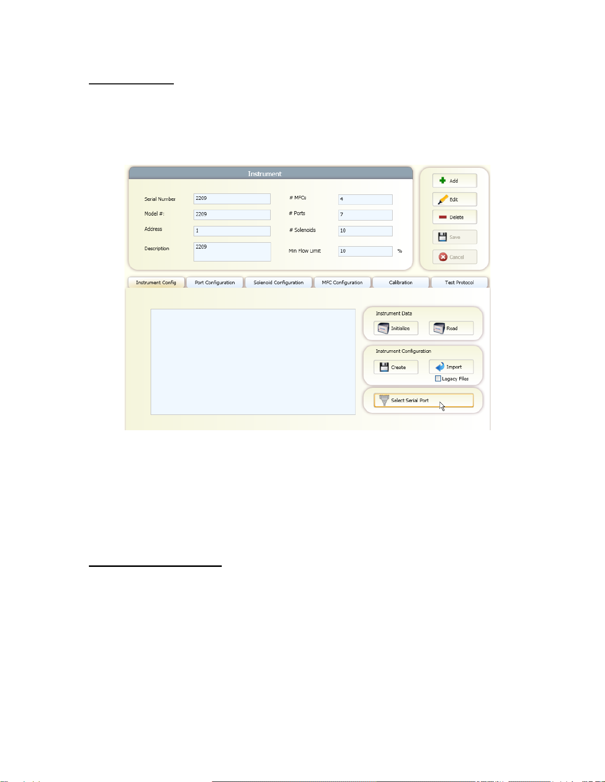
Serial port setup
To select the serial port used to communicate with the system:
1. Click on the "Instruments" tab.
2. Click "Select Serial Port" on the bottom right corner of the screen.
3. Select the desired COM port. The list will show all COM ports available on
the PC.
NOTE: If the COM port you are expecting is not displayed, this means
Windows has a problem with that COM port on your PC.
Installing Instrument Data
To install the instrument data for your system:
1. In the Instrument Configuration section, check the Legacy Files box.
2. Click the Import button and browse to the supplied CD containing the
instrument data files. Locate the DATA folder, and then locate the
SERIAL# folder that matches of serial # of your system. Click OK

BASIC CONFIGURATION
8
BASIC CONFIGURATION
The Basic Configuration functions are used to enter information on the Gases
and Cylinders that will be referenced by the instrument/s in Run Modes. This
information is common to all profiles and any changes made will be reflected in
the profiles using them.
The Gas Library provided contains over 100 commonly used gases. In addition,
custom gases can be created.
The Cylinder Library maintains a list of all cylinders you will be using in mixing or
diluting gases. Cylinders must be set up BEFORE the input of Port Assignments
can be defined.
GAS LIBRARY CONFIGURATION
The Gas Library defines the list of gases and corresponding physical
characteristics that are used by the instrument. Gases are referenced primarily
when defining cylinders and setting up run modes. The software comes with a
library of over 100 commonly used gases, and includes the ability to create your
own user-defined gases.
The Gas Library consists of a list that shows the current gases in the library. The
entry for each gas in the list shows:
Preferred Gas: Commonly used gases can be designated as "preferred"
by clicking on this box. Preferred gases appear at the top of the library.
Name: The name of the gas.
Symbol: The molecular symbol of the gas.
Specific Heat (Cp): The specific heat of the gas in ( cal / g ºC @ 25 ºC )
Density (d) : The density of the gas ( g / l @ 0 ºC )
Molecular Structure (N) : The molecular structure of the gas: (Monatomic,
Diatomic, Triatomic, or Polyatomic)
GCF: Gas correction factor of the gas.
To view the Gas Library:
1. Click the "Gases" button.
2. If you wish to mark commonly used gases as "Preferred," simply find them
in the library by scrolling down the list or by utilizing the Search window
found at the top of the library. Those marked as Preferred will always
appear at the top of the library.

BASIC CONFIGURATION
9
To add a User Defined Gas to the Gas Library:
1. From within the Gas Library, click on the "Add" button.
2. A blank Gas Edit form will appear at the bottom of the window. Enter the
Gas Name, Gas Symbol, Specific Heat, Density, and Molecular structure
(using pull down box). If you wish to make this a preferred gas, check the
"preferred gas" box.
3. Click "Save" to add the new gas to the library. Use defined gases are
added to the bottom of the Gas Library and have a yellow background.
To Edit a User Defined Gas in the Gas Library:
1. From within the Gas Library, find and click on the gas of interest. You can
do this by scrolling through the library or by using the Search window.
Once you highlight the gas to be edited, click the "Edit" button.
2. The Gas Edit form will open at the bottom of the window. Edit the desired
field/s.
3. Click "Save" to save the changes to the library. User defined gases are
added to the bottom of the Gas Library and have a yellow background.
To Make a Copy of a Gas in the Gas Library:
1. From within the Gas Library, find and click on the gas of interest. You can
do this by scrolling through the library or by using the Search window.
Once you highlight the gas to be edited, click the "Copy" button.
2. The Gas Edit form will open at the bottom of the window with the copied
information. Note that the software adds an asterisk (*) after the Gas
Name and Symbol. You can edit these, and other desired field/s but the
name and symbol must be unique.
3. Click "Save" to save the changes to the library. Copied gases, as user
defined gas, are added to the bottom of the Gas Library and have a yellow
background.
To Delete a User Defined Gas in the Gas Library:
1. From within the Gas Library, find and click on the desired gas of to be
deleted. You can do this by scrolling through the library or by using the
Search window.

BASIC CONFIGURATION
10
2. Highlight the gas to be deleted and click the "Delete" button. The gas will
be deleted immediately with no confirmation prompt, so be sure to verify
the correct gas is highlighted prior to hitting Delete
NOTE: Only User Defined Gases can be deleted from the library.
CYLINDER LIBRARY CONFIGURATION
The Cylinder Library maintains a list of all cylinders that will be used in mixing or
diluting gases. The Cylinder Library must be set up before the input Port
Assignments can be defined. An individual cylinder consists of one or more
component gases. Any gas in the Gas Library is available to be added to a
cylinder. Once created, cylinders are used for defining input port connections and
setting up the instrument run modes.
To open the Cylinder Library, click the Cylinder button. Existing cylinders
definitions can then be modified or new ones can be added.
The Cylinder Library form consists of the following information:
Cylinder Name: This is the name of the cylinder. You can assign any
name you want, but it is best to be descriptive (ex. "100ppm CO2 bal N2").
The currently selected cylinder is displayed here. To select a different
cylinder, click on the pull down box and select the desired cylinder from
the list by clicking on it.
Description: This is a user-defined field for storing any desired information
about a cylinder (serial number, description, etc). The software does not
use this information.
GCF: Gas correction factor of the cylinder. This is calculated automatically
based on the component gases and their concentrations, unless set to
MANUAL. When set to Manual, the user can enter the desired GCF.
Creation Date: This displays the date that the cylinder was created. This
value is generated automatically by the software and is not editable.
Expiry Date: This displays the expiration date of the cylinder. When used
with the Cylinder Auditing feature, the software will warn you about
cylinders that are approaching or are beyond their expiration date. By
default, newly created cylinders have no expiration date. To insert an
expiration date, uncheck the "Ignore Expiration" box and enter the desired
expiration date.

BASIC CONFIGURATION
11
To add a cylinder to the Cylinder Library
1. Click "Add" and enter a name for the new cylinder in the "Cylinder Name"
box.
2. Fill in the desired Information, GCF and Expiration Date value, if desired
(see above).
3. Enter the contents of the cylinder beginning with the balance gas. Using
the drop down menu "Select Gas," select the desired balance gas and
click "Add Gas." The concentration will be automatically set at 100%. If
you wish to display concentration in PPM, double click on the "%" in the
units column and then select PPM from the drop down menu.
4. Continue adding the remaining component gases in the same manner. If
you add a gas in error, you can remove it by clicking the "clear" button.
5. Once all gases have been added, enter the concentration of each
component gas under the concentration box. Remember, units can be
changed from ppm to % using the pull down box under units. The balance
gas concentration will automatically be filled in as the difference so that all
gases add up to 1 million ppm (100%).
Note: As you enter the gases and concentrations, the cylinder GCF will
automatically be computed based on the concentration of the individual
gases in the cylinder. This total GCF is displayed next to the cylinder
name. If you desire, the total GCF can be entered manually by clicking on
Manual in the top section and then typing the GCF value in the GCF box.
6. When done, click Save to save your cylinder.
Editing gases in a cylinder
The following buttons are present to assist editing the cylinder contents. To move
or remove a gas from a cylinder, you must first select the cylinder and click
"Edit."
Move Up: Moves the currently selected gas up one position in the table.
Move Down: Moves the currently selected gas down one position in the
table.
Clear: Deletes the selected gas from the cylinder contents table.
Gas Library: Brings up the Gas Library form, allowing the addition of new
gases while editing the current cylinder.

BASIC CONFIGURATION
12
To make a copy of an existing cylinder
1. Highlight the cylinder to be copied in the left hand window and click
"Copy." The software will add an astrisk (*) to the cylinder name. Enter a
new name for the copied cylinder in the "Cylinder Name" box.
2. Add or edit any component gases as above.
3. Once all gases have been added, enter the concentration of each
component gas under the concentration box. Remember, units can be
changed from ppm to % using the pull down box under units. The balance
gas concentration will automatically be filled in as the difference so that all
gases add up to 1 million ppm (100%).
4. When done, click Save to save your cylinder.
To delete a cylinder
1. Highlight the cylinder to be removed in the left hand window and click
"Delete."
2. A pop-up window will ask you to confirm deletion of this cylinder.
3. Click "Yes" to delete the cylinder.

BASIC CONFIGURATION
13
CYLINDER AUDITING
The Cylinder Auditing option allows the software to report cylinders that are
approaching their expiration date.
In order to use Cylinder Auditing, you must make sure that each cylinder in the
cylinder library that you wish to audit has an expiration date assigned (See
Cylinder Library help for more information).
To Activate Cylinder Auditing:
1. Click the Cylinders button.
2. Click the "Set Audit" button
3. In the pop-up window, check the Enable Auditing box and set the Audit
Range (days). The software will then identify cylinders that will expire
within the specific number of days.
To View Cylinder Auditing Report:
Click the View Audit Button at any time for a real time report on the status of all
cylinders that fall inside of the set Audit Range. The report lists the cylinder
name, expiration date, creation date, description and in how many days it
expires.

MANAGING PROFILES
14
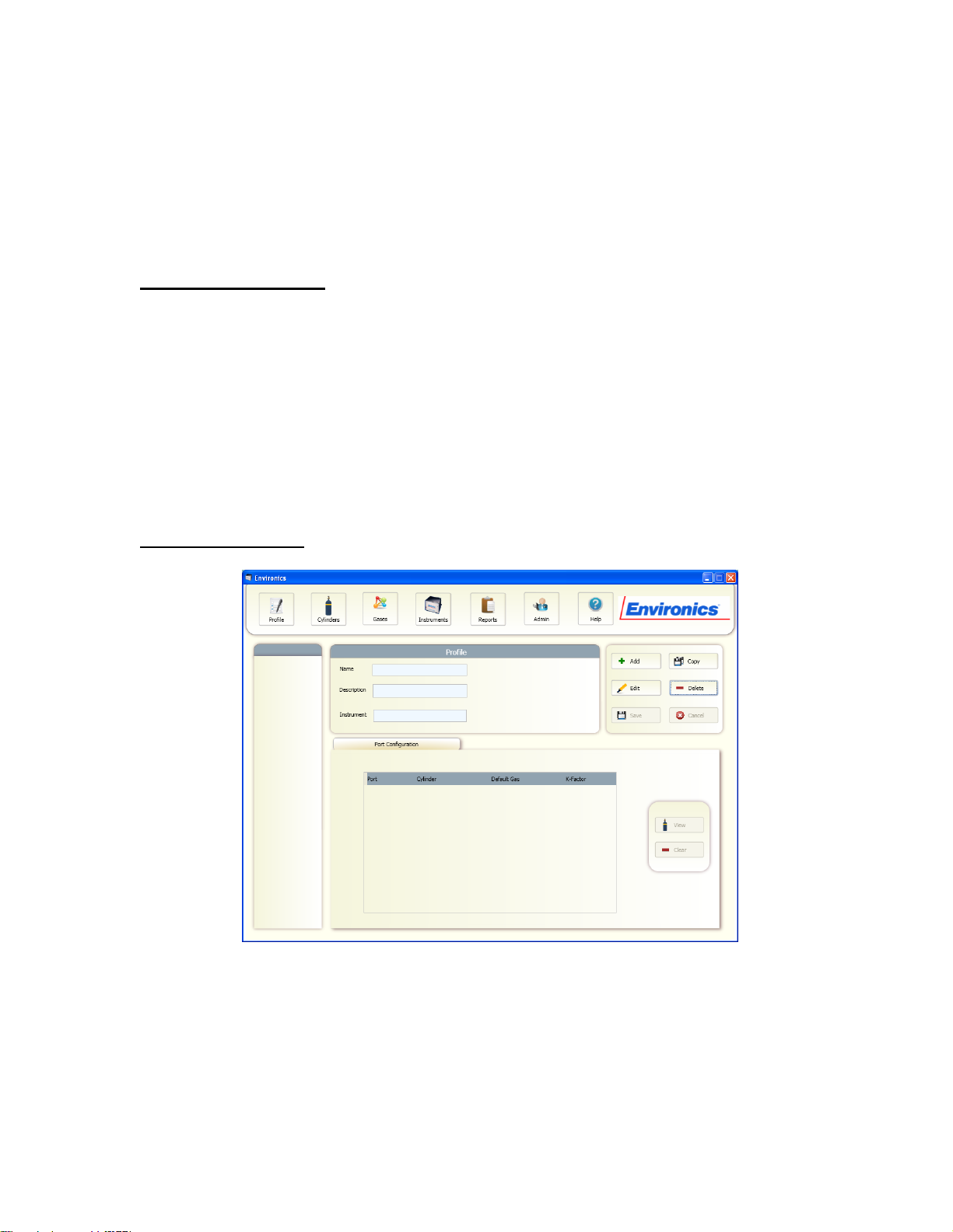
MANAGING PROFILES
Profiles are stored instrument set-ups that allow users to configure various
related tasks and group them together for easily operation. Saving these settings
allows you to quickly switch programs without having to manually re-enter
information related to that task.
Within the Profile, the following information is stored:
Instrument (by serial #)
All Cylinder-Port Assignments
All Concentration, Flow and Divider mode set-ups
All Program and Schedule mode set-ups
All Operating Modes are run through a Profile. Unique Profiles can be created for
each user, each instrument, each site or in a manner most convenient to you.
Some information is NOT stored along with a given Profile, but is common to all
Profiles. This includes:
Gas Library
Cylinder Library
Instrument Configuration and Calibration Settings.
Any modification made to these items will be reflected in all Profiles.
To Add a New Profile:
1. Click the "Profile" button.
2. Click the "Add" button. Select the Instrument to be associated with this
profile. Click OK
3. Enter a Name for the profile, and a Description (if desired).
4. In the Port Configuration section, select which Gas Cylinders are to be
assigned to which gas ports. This section can be filled in or edited later,
but must be completed before you can operate the system.
5. Click the "Save" button. Your Profile will now appear in the left hand
window.

MANAGING PROFILES
15
To Edit a Profile:
1. In the left window, click on the Profile you wish to edit
2. Click the "Edit" button
3. To change the Name/Description of the profile, simply change these items
as desired.
4. To change the Instrument associated with that profile, click the Instrument
box and select from the drop-down list.
5. To change the cylinder assigned to a port, click in the desired Cylinder
column. Double-click in the cylinder box, then select from the available
cylinders. Highlight the desired Cylinder to select it.
Once you select a cylinder, the default gas and GCF will be shown (these
can only be changed from within the Cylinder Library)
6. If you wish to remove a Cylinder from a Port, click the "Clear" button
7. Once all desired changes have been made, click "Save."
HINT: To see the components of a cylinder, click the desired Cylinder,
then click the "View" button
To Copy a Profile:
1. Click on the Profile you wish to copy.
2. Click "Copy".
3. Select the Instrument to use with the new profile.
4. A new profile will be created with the same name as selected, with a "*"
added to the end of the name. You can change the name if desired by
selecting the new profile, then clicking "Edit".
To Remove a Profile:
1. Click on the Profile you wish to configure in the left hand window.
2. Click "Delete".
3. Confirm removal of the Profile by clicking Yes in the pop-up window.

RUNNING THE INSTRUMENT
16
RUNNING THE INSTRUMENT
The various RUN modes allow the user to operate the instrument and specify the
desired gas concentration and flow.
There are three main RUN modes:
Concentration mode - allows you to specify the desired concentration of
gases and total flow rate of the output
Flow mode - allows you to specify the individual flow rate of each gas
Divider mode - provides an automatic 10 step dilution of a single gas
In addition, the Program mode and Schedule mode allow you to group
Concentration, Flow and Divider modes together into a set of step-by-step
operations (a program) and either run the program or schedule the operations to
run at a specific time and date.
CONCENTRATION MODE OVERVIEW
Concentration mode is used to create a blend by entering target gas concentrations
for each gas of interest, and the desired total output flow for the mix. The software
automatically computes the correct flow for each gas to achieve the desired output.
Concentration mode set-ups are created and saved within a desired Profile. Each
Mode set-up in the library is named by the user and contains the associated
concentration assignments for the individual cylinders and the total output.
The actual gas input ports and flow controllers used in Concentration mode are
automatically selected based on the specified cylinder and output concentrations.
Cylinders are mapped to ports based on the port configuration assigned by you when
configuring your profile (see Managing Profiles). Concentrations are mapped to
controllers based on the physical port to controller connections of the instrument.

RUNNING THE INSTRUMENT
17
CONFIGURING CONCENTRATION MODE
In order to create a new Concentration Mode, you must first create and
configure your Profile (see Managing Profiles).
To Add a New Concentration Mode:
1. Click the "Profile" button.
2. Select the desired Profile in the left hand window.
3. Verify the required instrument is selected for this profile and that the
Cylinders are properly assigned to the ports.
4. Click on "Concentration" below the Profile Name in the Left hand
window and then click "Add."
5. Enter a Unique Name for the Mode.
The Concentration Mode table on the bottom half of the screen allows you to
record and view the settings for the current Concentration Mode. These
settings include cylinder and concentration settings and total flow. The items
in the table are shown below:
Total Flow: Used to specify the total flow rate of the output.
Balance: Indicates which gas cylinder is to be used as a balance or
diluent gas.
Cylinder: The name of the gas cylinder.
Gas: Indicates the gas of interest for the cylinder. The gas of
interest indicates which gas to consider when specifying the Target OGC.
This is primarily used with multicomponent cylinders.
Target OGC: This is the desired output gas concentration for this
cylinder's specified gas of interest. If the cylinder is checked as the
BALANCE cylinder, this is automatically calculated based on the OGC
values for specified for the other cylinders.
Units: Selects the OGC units as either % or PPM. .
Actual OGC: Displays the actual output gas concentration, in the
units specified (% or PPM).
Units: Selects the OGC units as either % or PPM. .

RUNNING THE INSTRUMENT
18
To Add Concentration Mode Settings:
1. After naming the Concentration Mode, select the first cylinder you
wish to use from the "Select Cylinder" drop down menu and click "Add."
We suggest always adding the balance gas first. Only the cylinders you
have already assigned to this instrument can be selected.
2. Repeat this step until all desired cylinders have been added. To
remove a cylinder, click the "Clear" button.
3. Specify the balance gas using the click box in the first column.
4. Specify the component gas of interest for all desired cylinders (as
needed) using the drop down menu in the "Gas" column. If you would like
to view the contents of the cylinder, click the "View Cylinder" button.
5. The next step is to specify the desired target output concentration
(Target OGC) for each cylinder. Type the value in the Target OGC. If
desired, the units can be changed between ppm and % by using the pull
down box under "Units."
Note: The Target OGC for the balance gas is automatically calculated
and cannot be modified.
6. Enter the Total Flow by typing in its value. The units can be
changed from CCM to LPM by using the pull down menu under units. The
value entered is used by the system to compute the target concentration
of the balance gas and the required flow of each controller.
When entering data, the system will check that the values entered are
allowable, based on several factors, including Cylinder Gas Concentration,
Total Flow and the range of the Mass Flow Controllers. The software will
generate a warning and attempt to correct the entry so that it is an
acceptable value.
The actual ports and controllers used in this Concentration mode are
automatically selected based on the specified cylinder, gas concentrations
and total flow. Clicking on a particular cylinder in the table will display
information about the Port and Mass Flow Controller (MFC) selected by
the software. The maximum flow for that flow controller is displayed as
well.
7. To save the Mode, click the "Save" button.

RUNNING THE INSTRUMENT
19
To Edit a Setting in Concentration Mode:
1. Click the "Profile" button.
2. Select the desired Profile in the left hand window.
3. Select the Mode to edit by clicking the "+" beside Concentration in
the left hand window and then highlighting the desired mode.
4. Click "Edit." The Mode will open and any required changes can be
made in the same manner in which the mode was initially created (see
above).
5. To save the changes to the Mode, click the "Save" button.
To Copy a Concentration Mode:
1. Click the "Profile" button.
2. Select the desired Profile in the left hand window.
3. Select the Mode to copy by clicking the "+" beside Concentration in
the left hand window and then highlighting the desired mode.
4. Click "Copy." A duplicate Mode will open, designated by an asterisk
(*) after the Mode name. Rename the new Mode and edit as above.
5. To save the Mode, click the "Save" button.
To Remove a Concentration Mode:
1. Click the "Profile" button.
2. Select the desired Profile in the left hand window.
3. Select the Mode to delete by clicking the "+" beside Concentration
in the left hand window and then highlighting the desired mode.
4. Click on "Delete" and confirm the removal of the mode in the pop-
up window.

RUNNING THE INSTRUMENT
20
RUNNING CONCENTRATION MODE
In order to run a Concentration Mode, you must first create and configure
your Mode (see Concentration Mode Setup).
The Run Control section located on the right side of the lower portion of the
screen is used to run the specified gas concentrations. The instrument can be
run either manually or with a timer. Once the instrument is running, all
controls in the Concentration Mode form are disabled.
To Run Concentration Mode Manually:
1. Click the "Profile" button.
2. Select the desired Profile in the left hand window.
3. Click on "Concentration" below the Profile Name in the Left hand
window and then highlight the desired Mode.
4. Verify the settings in the Concentration Mode Table are correct.
5. Click the "Start" button to start flowing gases. The software will
display in real time the actual gas concentrations and flow rate. The run
status box will indicate the elapsed run time.
6. Click "Stop" to stop the flow of gas.
NOTE: While running, you can change between the default "Table View" and
a "Graphical View." The user can switch between them to see this information
in the format they prefer.
To Run Concentration Mode with a Timer:
1. Click the "Profile" button.
2. Select the desired Profile in the left hand window.
3. Click on "Concentration" below the Profile Name in the Left hand
window and then highlight the desired Mode.
4. Verify the settings in the Concentration Mode Table are correct.
5. To flow gases for a specific time duration, set the desired run time
in the Run Time box. You can enter the value directly, or use the up/down
arrows to set the time.
6. Click the "Start" button to start flowing gases. The instrument will
run for the specified length of time and then stop. While the instrument is
running, the run status box indicates the elapsed run time. The software
will display in real time the actual gas concentrations and flow rate.
7. If you wish to stop the flow of gas prior to the elapsed time running
down, click "Stop." The timer will display the time remaining. The Mode
can be resumed by clicking "Start."
This manual suits for next models
1
Table of contents


