1
Governors America Corp. © 2021 Copyright All Rights Reserved
EEG7500 Enhanced Electric Governor 8-2021-A8 PIB5115
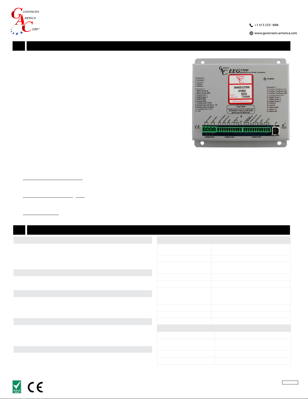
EEG7500
Enhanced Electronic Governor
1INTRODUCTION
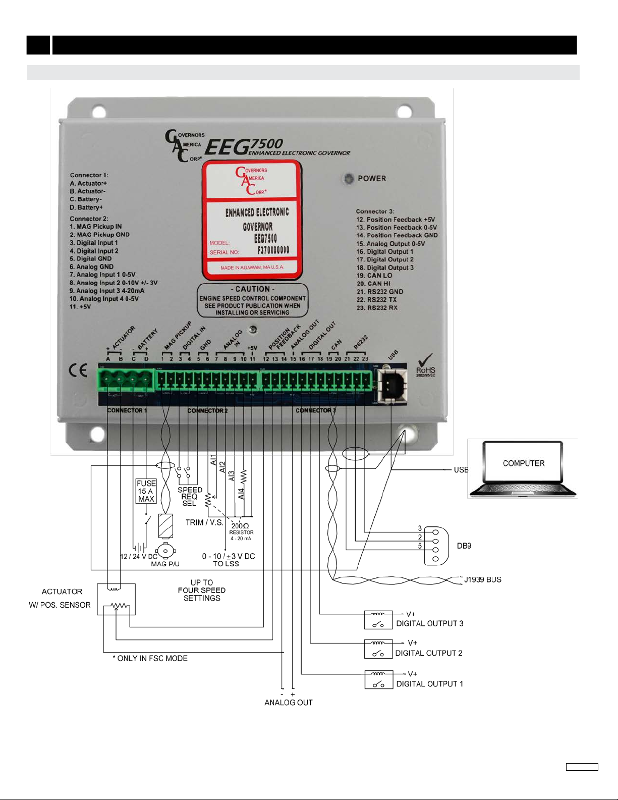
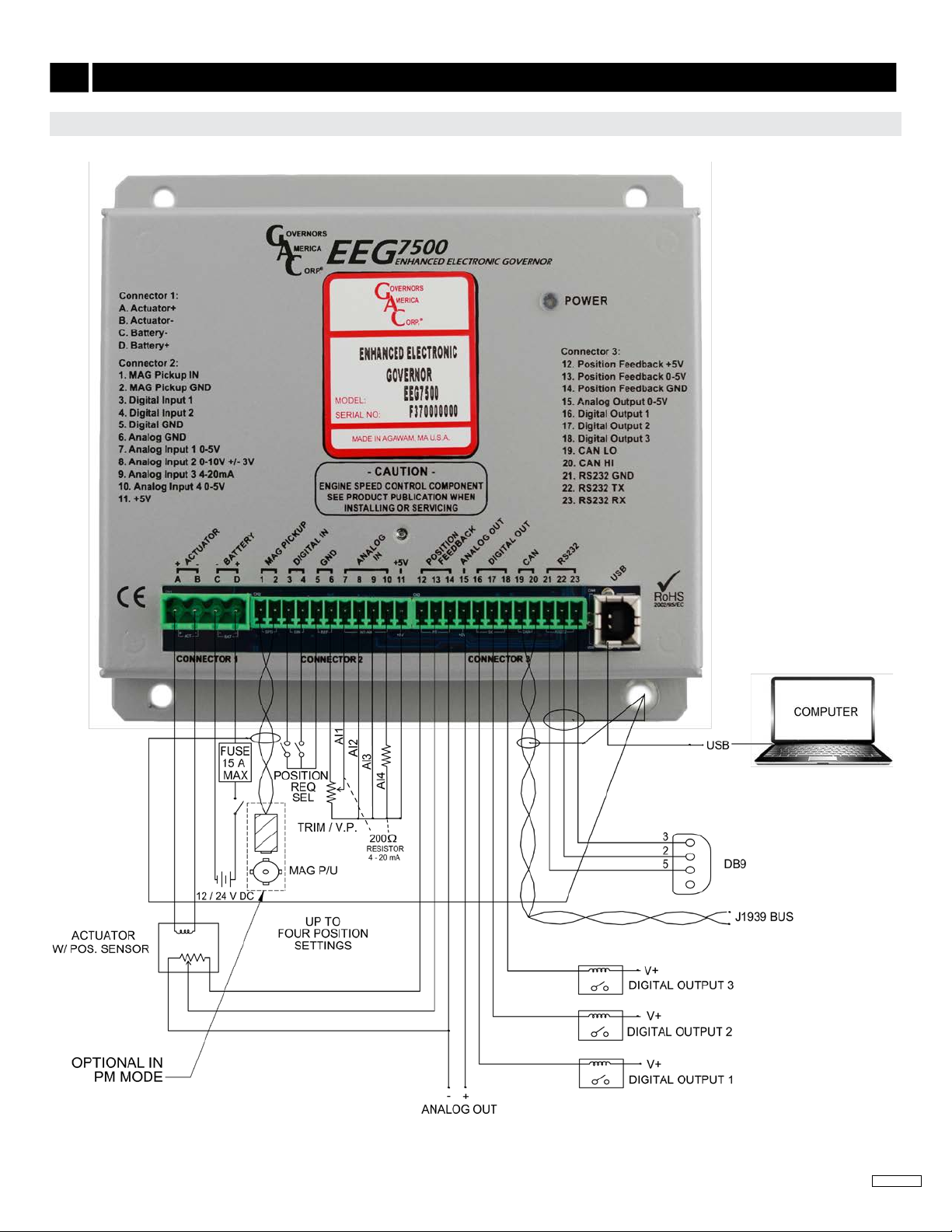
GAC’s EEG7500 enhanced electronic governor is designed to regulate engine speed
on diesel and gaseous fueled engines. When paired with a GAC actuator the EEG is
a suitable upgrade for any mechanical governor system that needs exibility, preci-
sion, or accurate control of governed speed. The EEG7500 is designed for industrial
engine applications from generator sets, mechanical drives, pumps, and compressors
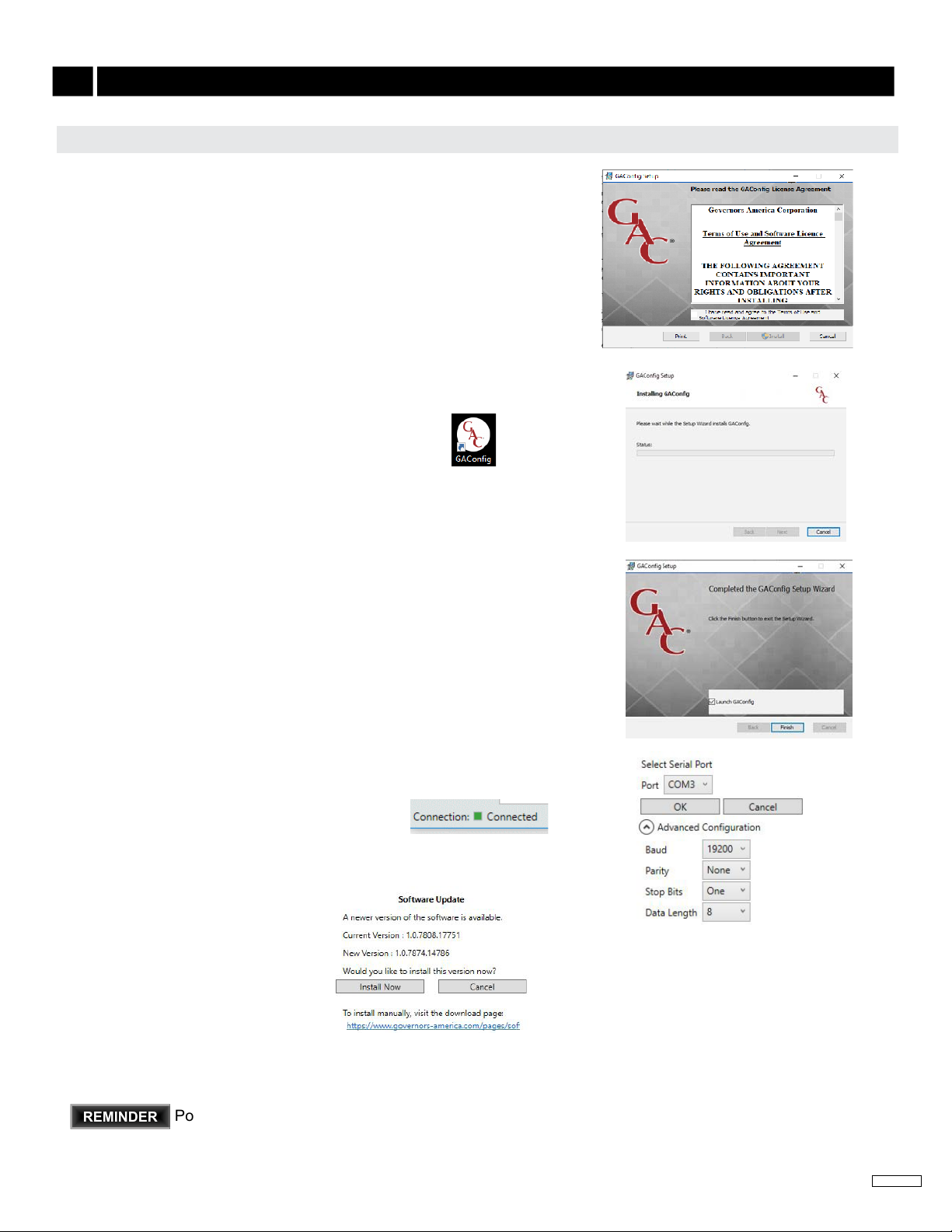
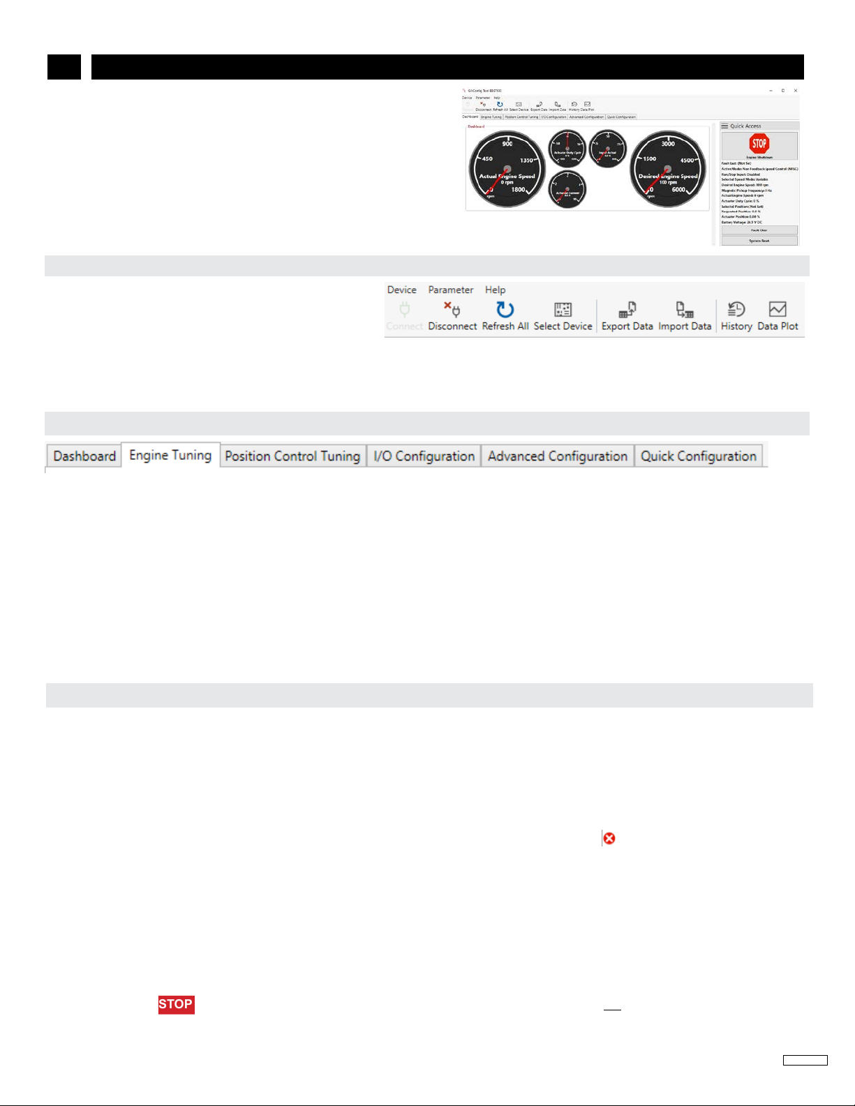
to o-road mobile equipment. Conguring is easy with GAC’s free GACong Tool
software. The EEG7500 supports:
Flexible actuator compatibility including bidirectional actuators with or without
actuator position feedback signal, bi-directional torque motors, and Bosch-style
throttle bodies.
Fully congurable digital and analog inputs and outputs
Inputs: 5 analog, 2 digital
Outputs: 1 analog, 3 digital
0 - 5 V DC, 4 - 20 mA, 0 - 10 V DC, or ±3 V DC input ranges
Speed Sync using CAN bus
Virtual Input/Output Routing
Feedback Speed Control Mode
Variable Speed Capability
Fuel Curve Shaping
EEG7500 supports three operating modes:
Non-Feedback Speed Control (NFSC) provides standard PID governing function for use with proportional actuators. No position
feedback sensor is required. PID (Proportional, Integral, Derivative) governor functions are optimized for best response and control
of the requested engine revolutions per minute (rpm).
Feedback Speed Control (FSC) combines NFSC and PM modes for use with proportional or bidirectional (torque motor) actuators. A
position feedback sensor is required. The Speed PID position request is the input to the Positioner loop, the Position PID optimizes
response and control of the requested actuator position.
Positioner Control (PC) (uncommon) provides actuator positioning control and is used with proportional actuators or bidirectional
(torque motor) actuators with a feedback sensor (required).
2
PERFORMANCE
Isochronous Operation ± 0.25 %
Governed Speed /
Sensor Frequency Range 100 Hz - 12 kHz
Droop Range Up to 25 % regulation
COMPLIANCE / STANDARDS
Agency CE and RoHS Requirements
Communications USB, RS-232-C, SAE J1939
PHYSICAL
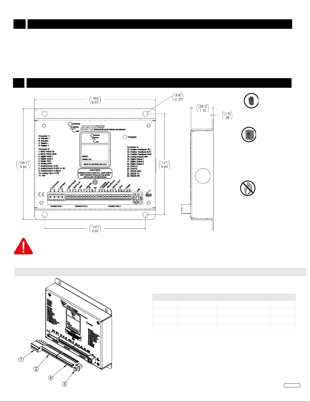
Dimension See Section 3, Controller Installation
Weight 18.4 oz [0.52 kgf]
Mounting Any position, vertical preferred
RELIABILITY
Vibration 10 - 2000 Hz @ 7 g, per SAE J1455
Shock 20 g, 11 ms per SAE J1455
Testing 100 % Functional Testing
LED
Solid Green Ready. Controller is powered on.
Blinking Green Warning. Engine service due, or other. Dis-
played in GACong Tool System Status.
Unlit No power.
INPUT / OUTPUT
Supply 12 - 24 V DC Battery systems
(6.5 to 32 V DC)
Polarity Negative Ground (Case Isolated)
Power Consumption 200 mA continuous plus actuator current
400 mA with excitation at MAX load current
Speed Sensor Signal Input 1.0 - 60.0 V RMS
Actuator Output 10 A Continuous
Load Share /
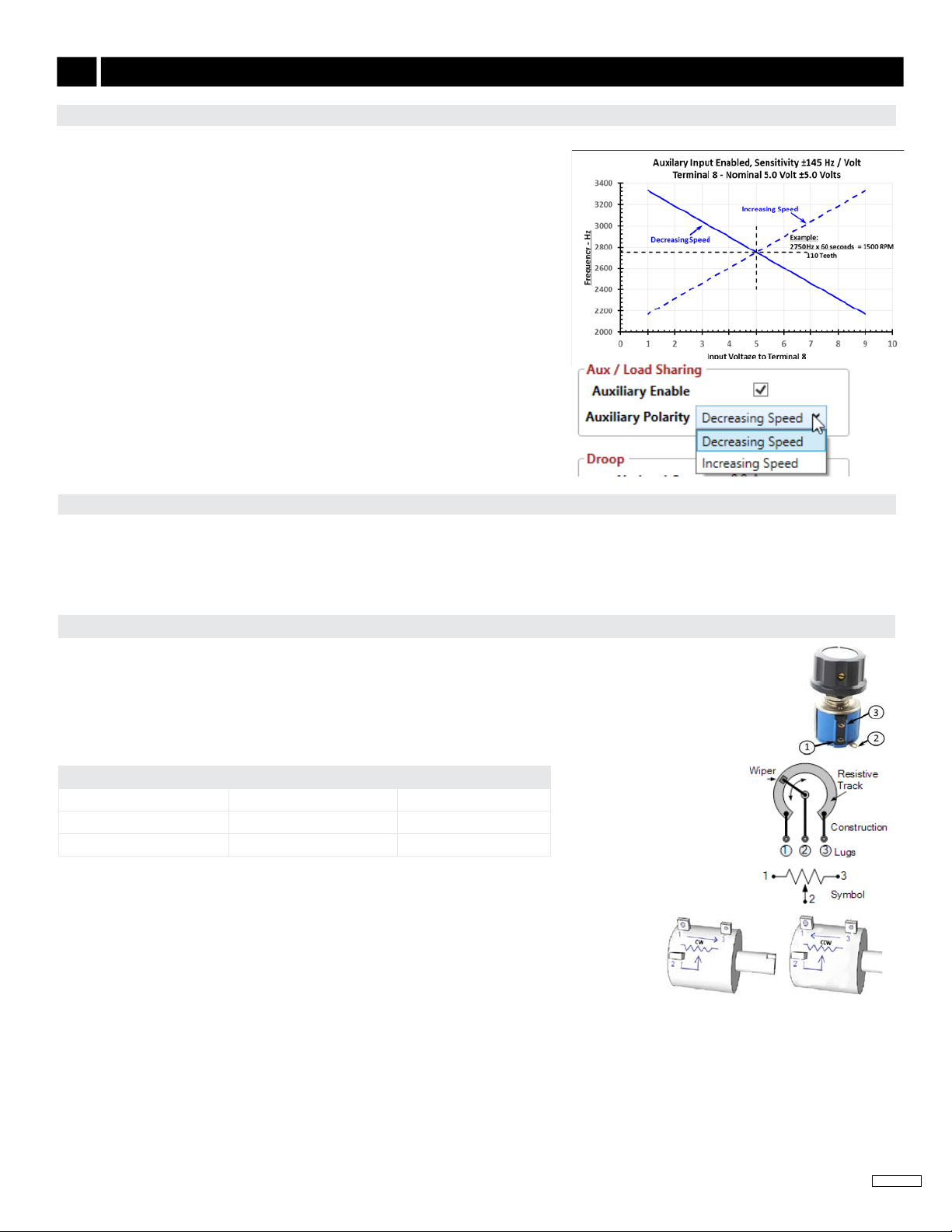
Synchronizer Input
0 - 10 V DC (5 V Nominal, Selectable
Polarity, 145 Hz / V Sensitivity)
or 0 V ± 3 V DC
Reverse Power Protection Protected to -40 V DC
Transient Voltage Protection 60 V DC
Digital Switch Output(s) Rated to 2 A DC
ENVIRONMENTAL
Ambient Temperature -40 to 180 °F [-40 to 85 °C]
Relative Humidity up to 90 % Non-Condensing
at 38 °C [100 °F] (per SAE J1455)
Salt Spray ASTM B117
All Surface Finishes Fungus Proof and Corrosion Resistant
EEG7500 SPECIFICATIONS