First issue 10/14 Release A10/14
PGRF 2/9
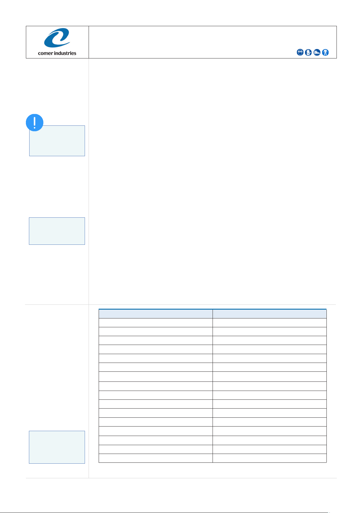
INDEX
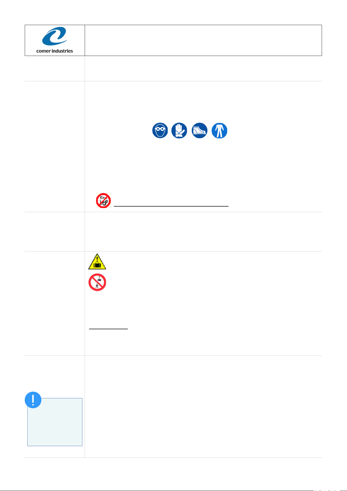
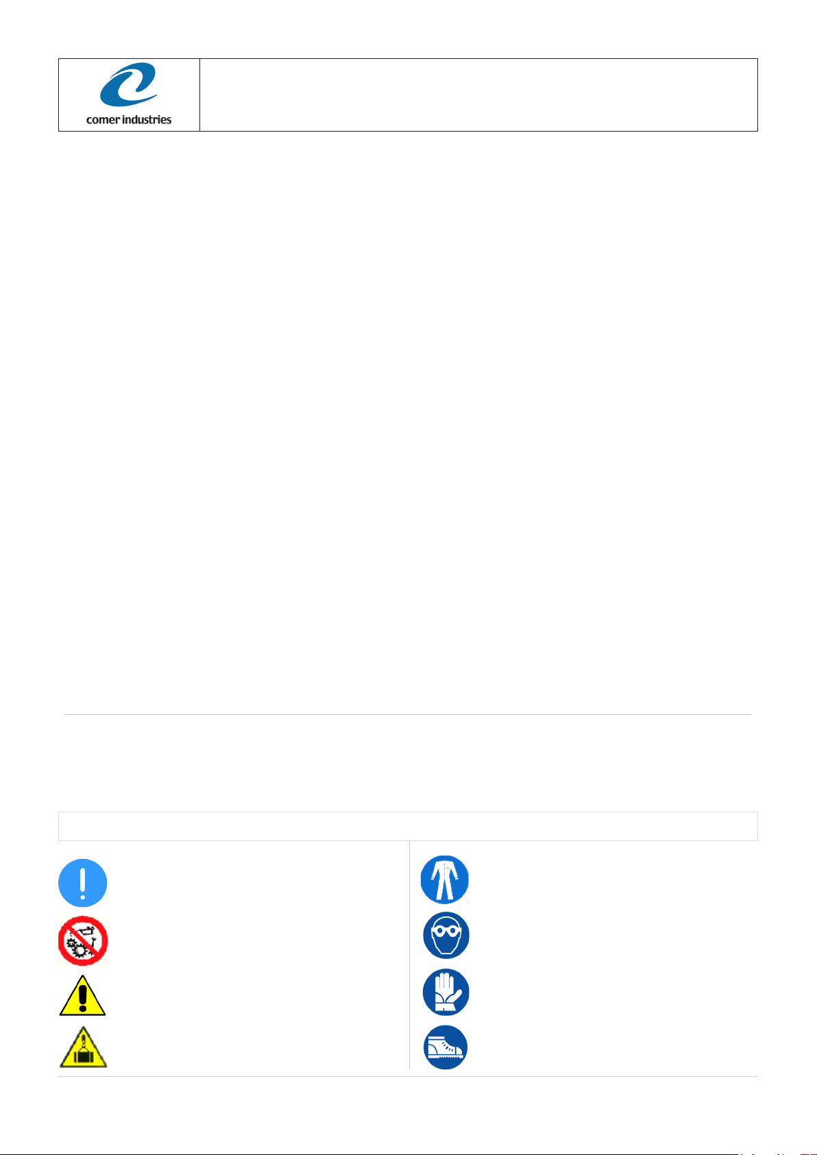
SYMBOLS USED
SAFETY SHOES
Safety shoes must be worn by all autorized people to
work on the reduction gear
SAFETY GLOVE
Safety glove must be worn by all autorized people to
work on the reduction gear
SAFETY GLASSES
Safety glasses must be worn by all autorized people to
work on the reduction gear
OBLIGATION
Operation to be observed
DANGER
Be careful of hanging loads
PROHIBITION
Do not work with machines in movement
PROTECTIVE CLOTHING
Protective clothing must always be worn by personnel
authorized to work with reduction gears.
WARNING
Operation must be carried out with extreme care with
personal injury if proper procedures are not followed
GENERAL INFORMATION....................................................................................................................................................................................... 3
GEARBOX UNIT IDENTIFICATION ............................................................................................................................................................. 3
RISKS AND PRECAUTIONS........................................................................................................................................................................ 3
TRANSFER AND STORAGE ....................................................................................................................................................................... 3
HANDLING ................................................................................................................................................................................................... 3
PRODUCT DISPOSAL ................................................................................................................................................................................. 3
GEARBOX UNIT........................................................................................................................................................................................... 4
INTENDED USE AND LIMITATIONS............................................................................................................................................................ 4
LUBRICANT ................................................................................................................................................................................................. 4
ORDINARY MAINTENANCE.................................................................................................................................................................................... 5
MAINTENANCE............................................................................................................................................................................................ 5
MAINTENANCE INTERVALS ....................................................................................................................................................................... 5
OIL REPLACEMENT PROCEDURE ........................................................................................................................................................................ 6
OIL DRAINING.............................................................................................................................................................................................. 6
OIL TOPPING OFF....................................................................................................................................................................................... 6
OIL FILLING.................................................................................................................................................................................................. 6
INSTALLATION AND START UP.................................................................................................................................................................. 7
PRELIMINARY CHECKS AND INSTALLATION ........................................................................................................................................... 7
START UP .................................................................................................................................................................................................... 7
MALFUNCTIONING AND FAILURE ............................................................................................................................................................. 7
FUNCTIONING INTERRUPTION.............................................................................................................................................................................. 7
TROUBLESHOOTING.............................................................................................................................................................................................. 8
TORQUE WRENCH SETTING ................................................................................................................................................................................. 9
This manual :
• provides all information about ordinary maintenance, installation and use for this unit,
• must be read and understood by the authorized people/operators before any kind of intervention,
• must be kept handy, in a safe place and must always be clear and legible for future reference whenever needed.