environmental potentials EP-2820 User guide

www.ep2000.com •800.500.7436
Power Quality For e Digital Age
EP-2800 SERIES
Installation and Application Manual

EP-2800 INSTALLATION GUIDE 2
EP-2800 Series
Installation and Maintenance Manual
Mailing Address: 1802 N. Carson Street, Suite 108-2132, Carson City, NV 89701
TEN YEAR WARRANTY
• Environmental Potentials will replace or repair any product from the EP-2800 product
line as long as it was not damaged during installation or damaged
from faulty installation.
• EP warranty registration card must be filled out and received by Environmental
Potentials within 15 days of installation.
• is warranty is for the repair or replacement of damaged EP products only.
Environmental Potentials accepts no liability, written or expressed, for the damage
that may have occurred to any other equipment; nor does Environmental Potentials
warranty cover any labor cost associated with replacement of such product.
Contact Us: warranty@ep2000.com •800.500.7436
Table of Contents
3 Safety First
3 Pre-Installation Preparations
4 Voltage Ratings & Power Source Configurations
6 Installation Diagram
7 Wiring Instructions
8 Bus Bar Installation

EP-2800 INSTALLATION GUIDE 4
EP-2800 Series Installation Procedures
Caution – Ungrounded power systems are inherently unstable and can produce excessively
high line-to-ground voltages during certain fault conditions. During these fault conditions
any electrical equipment, including an SPD, may be subjected to voltages which exceed their
designed ratings. is information is being provided to the user so that an informed decision can
be made before installing any electrical equipment on an ungrounded power system.
Suitable for use on a circuit capable of delivering not more than 200.000 rms symmetrical
amperes
LED Notification
• e modules come prewired for LED indication.
• ere are six wires, three black and three red, pre-
connected to a 6-pin housing.
• e LED is also pre-connected to a connector.
• Plug the 6-pin housing into the LED connector.
• Apply power after entire module installation is complete
and LED will provide visual notification of functionality.
• e green LED’s on the outside of the case indicate the
units are functioning properly. If a green LED becomes
extinguished this indicates a unit self sacrifice or
malfunction.
• e red LED’s on the modules identify which unit has
self sacrificed or malfunctioned.
Maintenance
EP products do NOT require periodic maintenance. e EP-
2800 Series provides visual and audible indications, remote
alarm with dry contacts.
It is also good practice to inspect the connections of the
power supply wiring to the EP unit monthly.
Servicing
EP units contain no serviceable parts and require no
adjustments. All EP products are designed to provide
many years of electrical protection without any need for
servicing.
Mounting
• For optimal performance mount the EP panel box
as close as possible to electrical panel.
• Can be rail mounted or bolted into wall or additional
panels with electrician supplied bolts and hardware.
• Longer wire increases inductance in the system
and the EP unit may not function properly.
• Make sure EP panel is mounted in a dry and clean
environment.
WIRING GUIDELINES
W G L F
#8 Within 1 Foot
#6 Between 1 - 3 Feet
#4 Between 3 - 6 Feet
#2 Between 6 - 10 Feet
Fuses
Please replace fuses with like fuses:
EP-2822 30A Slow Blow CC class 200KAIC
EP-2844 and EP-2888 30A Slow Blow J class
200KAIC

5
EP-2800 INSTALLATION GUIDE
Voltage Ratings & Power Source Configurations
1. Connect white neutral to neutral bus bar.
2. Next connect black phase A to phase A of the 100 A breaker.
3. Last connect green ground to ground bus bar or panel. Ground is case ground only
and should NOT be connected to neutral bus bar.
SINGLE PHASE WYE
PRODUCTS
EP-2820
EP-2840
EP-2880
VOLTAGE
ID# MCOV
1Y120 120 V
1Y240 240 V
1. Connect white neutral to neutral bus bar.
2. Next connect black phase A to phase A of the 100 A breaker.
3. en connect black phase B to phase B of 100 A breaker.
4. Last connect green ground to ground bus bar or panel. Ground is case ground only and
should NOT be connected to neutral bus bar.
TWO PHASE WYE
PRODUCTS
EP-2820
EP-2840
EP-2880
VOLTAGE
ID# MCOV
1S240 120 V
Connect white neutral to neutral bus bar.
1. Next connect black phase A to phase A of the 100 A breaker.
2. en connect black phase B to phase B of 100 A breaker.
3. en connect black phase C to phase C of 100 A breaker.
4. Last connect green ground to ground bus bar or panel. Ground is case ground only and
should NOT be connected to neutral bus bar.
THREE PHASE WYE
PRODUCTS
EP-2820
EP-2840
EP-2880
VOLTAGE
ID# MCOV
3Y208 120 V
3Y240 120V
3Y480 277V
3Y600 347V
L
N
Single Phase 1 Wire + Neutral
L1
N
L2
Split Phase 2 Wire + Neutral
L1
N
L2
L3
3 Phase Wye 3 Wire + Neutral
Single Phase Two Wire + Ground Installation
ree Phase Wye Installation
Split Phase Wye Installation
EP-2800 INSTALLATION GUIDE 6
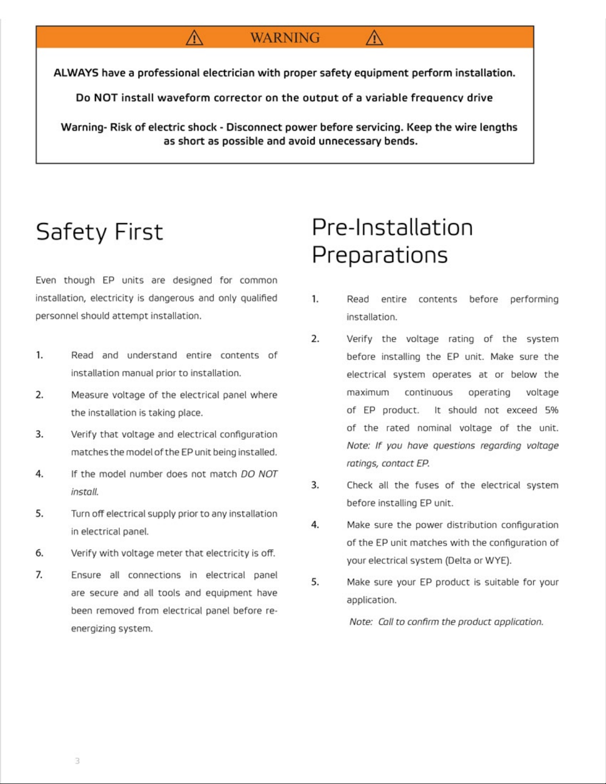
1. Connect black phase A to phase A of the 100 A breaker.
2. Next connect black phase B to phase B of 100 A breaker.
3. en connect black phase C to phase C of 100 A breaker.
4. Last connect green ground to ground bus bar or panel. Ground is case ground only
and should NOT be connected to neutral bus bar.
THREE PHASE DELTA
PRODUCTS
EP-2820
EP-2840
EP-2880
VOLTAGE
ID# MCOV
3D240 240V
3D480 480V
L1
L2
L3
3 Phase Delta 3 Wire
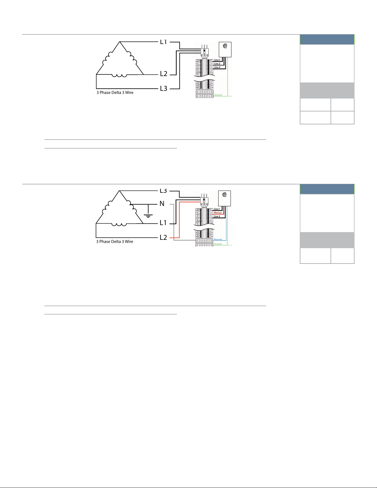
L3
L1
L2
3 Phase Delta 3 Wire
N
1. Connect black phase A to phase A of the 100 A breaker.
2. Next connect black phase B to phase B of 100 A breaker.
WARNING: Be sure that phase B is the HIGH LEG.
3. en connect red phase C to phase C of 100 A breaker.
4. Last connect green ground to ground bus bar or panel. Ground is case ground only
and should NOT be connected to neutral bus bar.
3 PHASE HL DELTA
PRODUCTS
EP-2820
EP-2840
EP-2880
VOLTAGE
ID# MCOV
3H240 120/
240V
ree Phase Delta Installation
ree Phase High Leg Delta Installation

7
EP-2800 INSTALLATION GUIDE
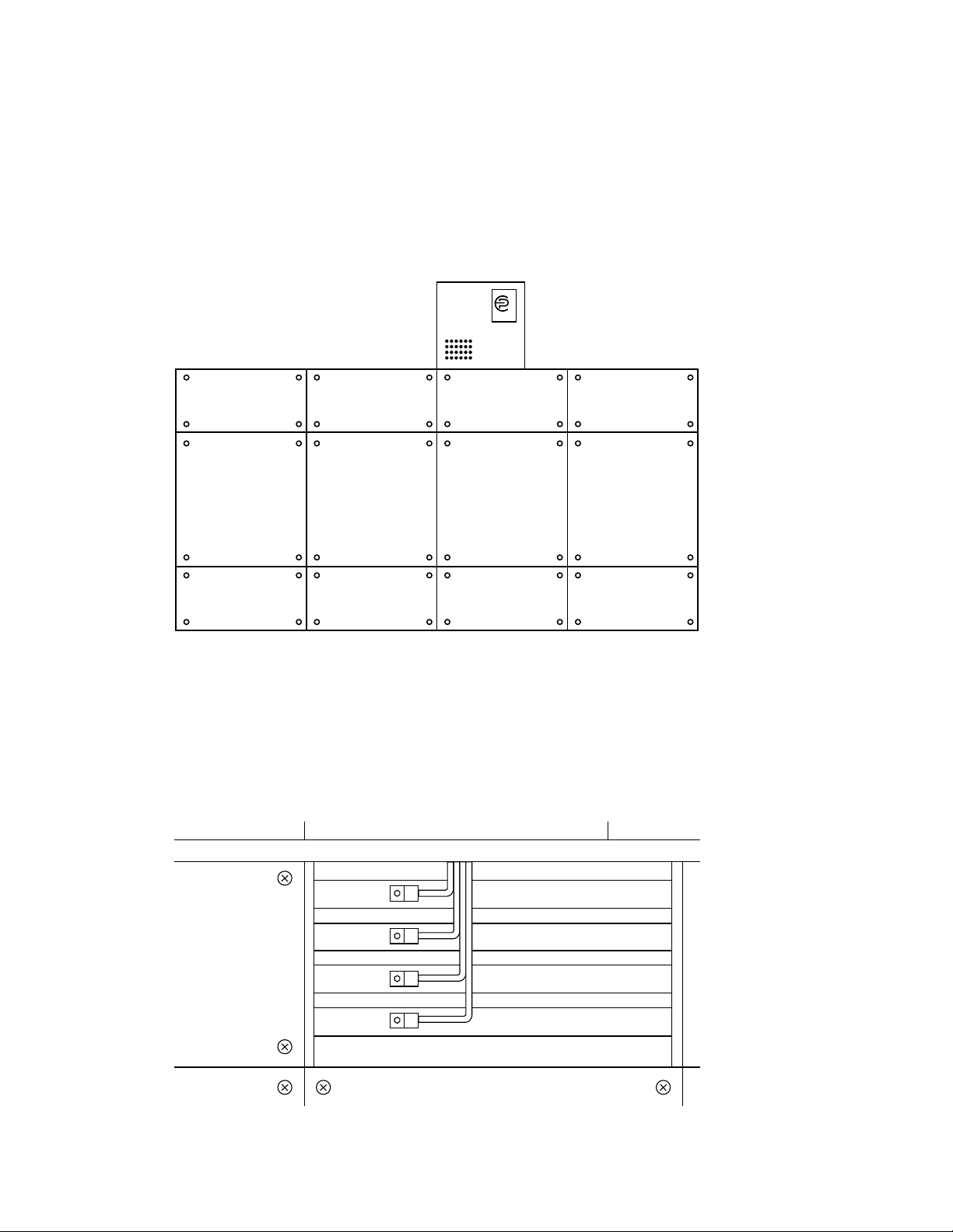
e 2800 is a Type 1 and type 2 waveform corrector and can be connected via a
circuit breaker, molded case switch, fused switch, or connected directly to the bus
bar.
Neutral Bar
Uninsulated
Ground Bar
Terminal Block
Replaceble
Modules
3 Pole
100 Amp
Circuit Braker
Conduit & Phase Wire
not provided by EP
Conduit Collar
Internal Fusing
Please note: Wire is supplied by contractor & should conform to the following guidelines:
EP2820: # 6AWG
EP2840: # 4AWG
EP2880: # 2AWG
EP-2800 Series Wiring Diagram

EP-2800 INSTALLATION GUIDE 8
Wye Installation
1. Cut hole in case
2. Connect green ground to the green ground connection of terminal block
3. Connect white neutral to the neutral terminal block.
4. Connect black phase a to phase a of the terminal block
5. Connect black phase b to phase b of the terminal block
6. Connect black phase c to phase c of the terminal block
7. Place phase, ground and neutral wires into conduit and feed to the panel
8. Connect green ground to the ground connection
9. Connect white neutral to the neutral bus.
10. Connect black phase a to phase a of the 100 a circuit breaker
11. Connect black phase b to phase b of the 100 a circuit breaker
12. Connect black phase c to phase c of the 100 a circuit breaker
* Ground is always connected to the neutral bus at the main service
Delta Installation:
1. Cut hole in case
2. Connect green ground to ground terminal block
3. Connect black phase A to phase A of the terminal block
4. Connect black phase B to phase B of the terminal block
5. Connect black phase C to phase C of the terminal block
6. Place phase wires into conduit and feed to the panel
7. Connect green ground to the ground connection
8. Connect black phase A to phase A of the 100 A circuit breaker
9. Connect black phase B to phase B of the 100 A circuit breaker
10. Connect black phase C to phase C of the 100 A circuit breaker
* Ground is always connected to the neutral bus at the main service
9
EP-2800 INSTALLATION GUIDE
Bus Bar Installation
1. Mount 28/2900 to top/side of switchgear cabinet
2. Use chase nipple and nut or other appropriate hardware to attach to switchgear panel
and to insure the protection of conductors passing between cabinets (wire provided by installer)
3. Open bus panel to expose bus bars
4. Bolt appropriate lugs to bus bars to accept wires from 28/2900
5. Route wires from 28/2900 to the bus area of switchgear panel
6. Attach phase, ground and neutral if equiped to appropriate bus bars
®
2800
2800/2900

EP-2800 INSTALLATION GUIDE 10
7. Inside 28/2900 enclosure in the middle toward the bottom is a fuse block that the phase wires connect
to and beside it is a ground terminal mounted to the DIN rail that the fuse block is hooked to
8. e Neutral if equiped goes directly to the distibution block directly above the fuse block
9. Detail area shows details of connections inside the 28/2900
Neutral
connection
Case Wall
Case Wall
Ground
Neutral
3 Phase
connections go here
This manual suits for next models
3
Table of contents
Popular Industrial Equipment manuals by other brands


SMC Networks
SMC Networks EX260-MPN1 instruction manual

Schrack
Schrack LSZDW001 operating instructions

Maxcess
Maxcess Tidland Performance Series Installation, operation and maintenance

ABB
ABB RobotStudio 2022.1 Release notes

Grease Guardian
Grease Guardian GGX75 System manual

Schleuniger
Schleuniger PreFeeder 1100 manual


