FlexDSL GigaFlex Series User manual

FlexDSL GigaFlex
DIN-RAIL UNITS
TECHNICAL DESCRIPTION AND INSTALLATION MANUAL
Version 1.1
Document name UM_Flexdsl-Gigaflex_Installation_V1-1.Docx
Revision 11 October 2019

Technical Description and Installation Manual GigaFlex
2
© Copyright 2019 by FlexDSL Telecommunications AG. The content of this publication may not
be reproduced in any part or, as a whole, transcribed, stored in a retrieval system, translated into
any language, or transmitted in any form or by any means, electronic, mechanical, magnetic,
optical, chemical, photocopying, manual, or otherwise, without the prior written permission of
FlexDSL Telecommunications AG. Published by FlexDSL Telecommunications AG. All rights
reserved.

Technical Description and Installation Manual GigaFlex
3
VERSION CONTROL.................................................................................................................4
SAFETY REGULATIONS ..........................................................................................................4
EU DIRECTIVE 2002/96/EC AND EN50419 ..............................................................................4
1SELECTION GUIDE ...........................................................................................................5
2PRECAUTION ....................................................................................................................6
3TECHNICAL DESCRIPTION ..............................................................................................7
3.1 General Information......................................................................................................7
3.2 LED Indicator and Connector Pin Assignment on Front Panel......................................8
3.3 GigaFlex Interface Description ...................................................................................11
3.3.1 SHDSL Interface..................................................................................................11
3.3.1.1 Modulation and Data Rates..........................................................................11
3.3.1.2 SHDSL Annex A/B.......................................................................................12
3.3.1.3 Bonding Group.............................................................................................12
3.3.1.4 Master and Slave Mode ...............................................................................12
3.3.1.5 Topologies ...................................................................................................12
3.3.1.5.1 Point-to-Point............................................................................................12
3.3.1.5.2 Point-to-Multipoint (Star Structure)............................................................13
3.3.1.5.3 Daisy Chain (Line Structure).....................................................................13
3.3.1.5.4 Ring Structure...........................................................................................13
3.3.1.5.5 Interface Conversion and Redundancy.....................................................14
3.3.2 Ethernet Interfaces...............................................................................................14
3.3.2.1 Power Over Ethernet (PoE)..........................................................................15
3.3.3 Serial Interface.....................................................................................................15
3.3.4 Inputs and Outputs...............................................................................................15
3.3.5 LCT USB Connector ............................................................................................16
3.3.6 SD Card and USB Host........................................................................................16
3.3.7 Factory Default Button, Default IP Address..........................................................16
4INSTALLATION................................................................................................................17
4.1 General Requirements ...............................................................................................17
4.2 Unpacking the Unit.....................................................................................................17
4.3 Mounting on DIN-rail ..................................................................................................17
4.4 Connecting Power Input and Protective Ground.........................................................18
4.5 Connecting Interface Cables ......................................................................................18
4.6 Power on the Device..................................................................................................18
5MAINTENANCE................................................................................................................19
6TECHNICAL SPECIFICATION .........................................................................................20
6.1 Interfaces...................................................................................................................20
6.1.1 SHDSL Interface..................................................................................................20
6.1.2 1000Base-X Ethernet (SFP) ................................................................................20
6.1.3 10/100/1000Mbps Ethernet (GE) .........................................................................20
6.1.4 Serial Interface.....................................................................................................20
6.1.5 Digital Input / Output Interface (2I2O)...................................................................20
6.1.6 USB Host.............................................................................................................21
6.1.7 Monitor or Local Craft Terminal USB Interface.....................................................21
6.1.8 SD Card Slot........................................................................................................21
6.2 Power over Ethernet (PoE).........................................................................................21
6.3 Power Supply.............................................................................................................21
6.4 Environment...............................................................................................................22
6.4.1 Climatic Conditions..............................................................................................22
6.4.2 Safety / EMC........................................................................................................22
6.5 Physical Dimensions and Weight ...............................................................................22

Technical Description and Installation Manual GigaFlex
4
VERSION CONTROL
Manual
Version
Date
Major changes to previous version
1.0
07.02.2019
Initial Version
1.1
11.10.2019
Chapter 1 Selection Guide
Chapter 2 Precaution
Figure 3-2 corrected
Table 3-1 corrected
Chapter 3.3.1.4 Master and Slave Modeted
Chapter 3.3.2.1 Power Over Ethernet (PoE)orrected
Chapter 6.1.5 Digital Input / Output Interface (2I2O)corrected
Chapter 6.3 Power Supplyrected
Chapter 6.4.2 Safety / EMC
SAFETY REGULATIONS
IF THE UNIT IS NOT USED IN ACCORDANCE TO REGULATIONS DESCRIBED AND DEFINED IN THE
CHAPTERS TECHNICAL DESCRIPTIO FLEXDSL
TELECOMMUNICATIONS AG REFUSES TO TAKE ANY RESPONSIBILITY. FURTHERMORE, NO
WARRANTY IS GRANTED IN SUCH CASE!
ONLY ALLOWED TO USE EXTERNAL POWER SUPPLYS THAT ARE APPROVED ACCORDING
TO THE SAFETY STANDARD IEC/EN 60950-1.
THE DISCONNECTING DEVICE FOR THE RACK IS THE MAINS PLUG AND/OR THE APPLIANCE
COUPLER. THE MAINS PLUG AND/OR THE APPLIANCE COUPLER HAS/HAVE TO BE EASILY
ACCESSIBLE AND THE MAINS PLUG HAS TO BE NEXT TO THE RACK IF THE MAINS PLUG SERVES
AS THE DISCONNECTING DEVICE.
ONLY ALLOWED TO USE THE UNITS WITH HOUSINGS SUPPLYED FROM FLEXDSL
TELECOMMUNICATIONS AG (SUBRACKS, MINIRACK, UTTX). THE RACK HAS TO BE CONNECTED
PERMANENTLY TO A RELIABLE PROTECTIVE EARTH CONDUCTOR. THE LTU UNIT AND
LINECARDS HAVE TO BE FIXED TO THE RACK PERMANENTLY WITH THE TWO PANEL SCREWS.
INCORRECT USE OF THIS DEVICE, USE IN ANY OTHER ENVIRONMENT AND/OR HOUSING THAN
PROVIDED BY FLEXDSL MIGHT LEAD TO HARMFUL CONDITIONS. FAILURE TO FOLLOW THESE
PRECAUTIONS MAY RESULT IN DEATH, SEVERE INJURY OR PROPERTY DAMAGE.
Please read this manual carefully before operating the system.
Installation of this equipment must be done by qualified personnel only.
EU DIRECTIVE 2002/96/EC AND EN50419
Our equipment is marked with the recycling symbol. It means that at the end of
the life of the equipment you must dispose it separately at an appropriate
collection point and not place it in the normal domestic unsorted waste stream.
(European Union only)

Technical Description and Installation Manual GigaFlex
5
1 SELECTION GUIDE
Functionality
FlexDSL GigaFlex Models
2x SHDSL (EFM)
4x SHDSL (EFM)
4x Ethernet 10/100/1000Base-TX
2x SFP 1000Base-X
2x RS232/422/485/
2x Input, 2x Output
IEEE1588 PTP (1-step) SyncE
IEEE1588 PTP (2-step) SyncE
MACsec
PoE
GF-RAIL2N-6Eth-2I2O/2SER-24V,V21
*1
*1
GF-RAIL2N-6Eth-2I2O/2SER-PoE-24V,V25
*1
*1
GF-RAIL2N-6Eth-24V,V26
*1
*1
GF-RAIL4N-6Eth-2I2O/2SER-24V,V31
*1
*1
GF-RAIL4N-6Eth-2I2O/2SER-PoE-24V,V35
*1
*1
GF-RAIL4N-6Eth-24V,V36
*1
*1
GF-RAIL4N-6EthP-2I2O/2SER-24V,V41
*2
*2
GF-RAIL4N-6EthP-2I2O/2SER-PoE-24V,V45
*2
*2
GF-RAIL4N-6EthP-24V,V46
*2
*2
*: Future software development
1: For 10/100/1000Base-TX and DSL Ports only
2: For 10/100/1000Base-TX, DSL and SFP Ports

Technical Description and Installation Manual GigaFlex
6
2 PRECAUTION
The present document describes the FlexDSL GigaFlex product family. The document contains
the technical description and the installation instruction of all devices. Appendices containing
additional information about the system are also an integral part of the present document.
WARNING
THIS EQUIPMENT IS NOT SUITABLE FOR USEIN LOCATIONS WHERE CHILDREN ARE
LIKELY TO BE PRESENT.
WARNING
BEFORE STARTING OPERATING THE EQUIPMENT, READ CAREFULLY THE CURRENT
MANUAL AND THE INSTALLATION MANUAL. FLEXDSL TELECOMMUNICATIONS AG
REFUSES NEITHER TAKING ANY RESPONSIBILITY NOR GRANTING ANY WARRANTY
TO ANY DEVICE MALFUNCTIONING OR ANY DAMAGES DUE TO FAILURE TO COMPLY
WITH THE REQUIREMENTS STATEDIN THE MANUALS, ESPECIALLY IN THE SECTION
WARNING
IMPROPER USE OF OUR EQUIPMENT, USE IN ANY OTHER ENVIRONMENT OR
IMPROPER INSTALLATION AND MAINTENANCE MIGHT LEAD TO HARMFUL
CONDITIONS. FAILURE TO FOLLOW THESE PRECAUTIONS MAY RESULT IN DEATH;
SEVERE INJURY OR PROPERTY DAMAGE.
FLEXDSL TELECOMMUNICATIONS AG REFUSES NEITHER TAKING ANY
RESPONSIBILITY NOR GRANTING ANY WARRANTY IN SUCH CASE.
WARNING
ELECTRONIC MODULES CAN BE DAMAGED OR DECREASED IN RELIABILITY BY
STATIC ELECTRICAL DISCHARGE. BEFORE HANDLING MODULES, WEAR AN
ANTISTATIC DISCHARGE WRIST STRAP TO PREVENT DAMAGE TO ELECTRONIC
COMPONENTS. PLACE MODULES IN ANTISTATIC PACKING MATERIAL WHEN
TRANSPORTING OR STORING. WHEN WORKING ON MODULES, ALWAYS PLACE
THEM ON AN APPROVED ANTISTATIC MAT THAT IS ELECTRICALLY GROUNDED. TO
PREVENT ELECTRICAL SHOCK, DO NOT INSTALL EQUIPMENT IN A WET LOCATION
OR DURING A LIGHTNING STORM.
WARNING
THE PROTECTIVE GROUND CONNECTION MUST BE APPLIED TO THE UNIT. MAKE
SURE THAT THE UNIT AND ALL EQUIPMENT CONNECTED TO IT USE THE SAME
PROTECTIVE GROUND FOR THE PURPOSE OF REDUCING NOISE INTERFERENCE
AND SAFETY HAZARDS.
Technical Description and Installation Manual GigaFlex
7
3 TECHNICAL DESCRIPTION
3.1 General Information
The FlexDSL GigaFlex product family is designed to support high speed data transmission over
copper andfiber cables with a complete Layer2/3 Ethernet switching functionality. Itfully complies
with the field-proven ITU-T G.991.2 SHDSL technology and IEEE 802.3ah Ethernet in the First
Mile (EFM) encapsulation. Unlike ATM encapsulation, the EFM frames have the same structure
as Ethernet IEEE 802.3 frames. This makes the bandwidth utilization more effective. The EFM-
based G.SHDSL transceiver operates as PHY (Physical Layer of OSI model). It can combine
several physical links into one logical link for obtaining more bandwidth. This process is called
bonding. SHDSL represents the best of several symmetric DSL technologies that have been
combined into a single industry standard providing rate adaptation, greater reach and
performance, spectral compatibility, lower power and application flexibility.
The FlexDSL GigaFlex product family offers the following features:
•A dual wide range 24/48VDC power input in case power supply redundancy is needed.
•An USB 2.0 Host interface to connect an additional USB flash stick for saving/restoring
configuration/firmware.
•A microSD card tray to insert a formatted microSD card with any capacity for
saving/restoring configuration/firmware.
•A Factory Default button to switch the devices configuration to factory default settings.
•Two cages for SFP modules support the 1000Base-X standard. They can be usedfor data
transmissionover fiber-optic cables as wellas copper cables (Ethernet 10/100/1000Base-
TX or VDSL2), depending on inserted SFP modules.
•Four standard 10/100/1000Base-TX Ethernet interfaces.
•Up to four SHDSL interfaces with up to 60Mbps.
•Two configurable RS232/422/485 serial interfaces.
•Two Inputs (current detection) and two Outputs (relays).
•Easy installation on DIN-rail (TS 35, EN 50022).
•Robust metal housing.
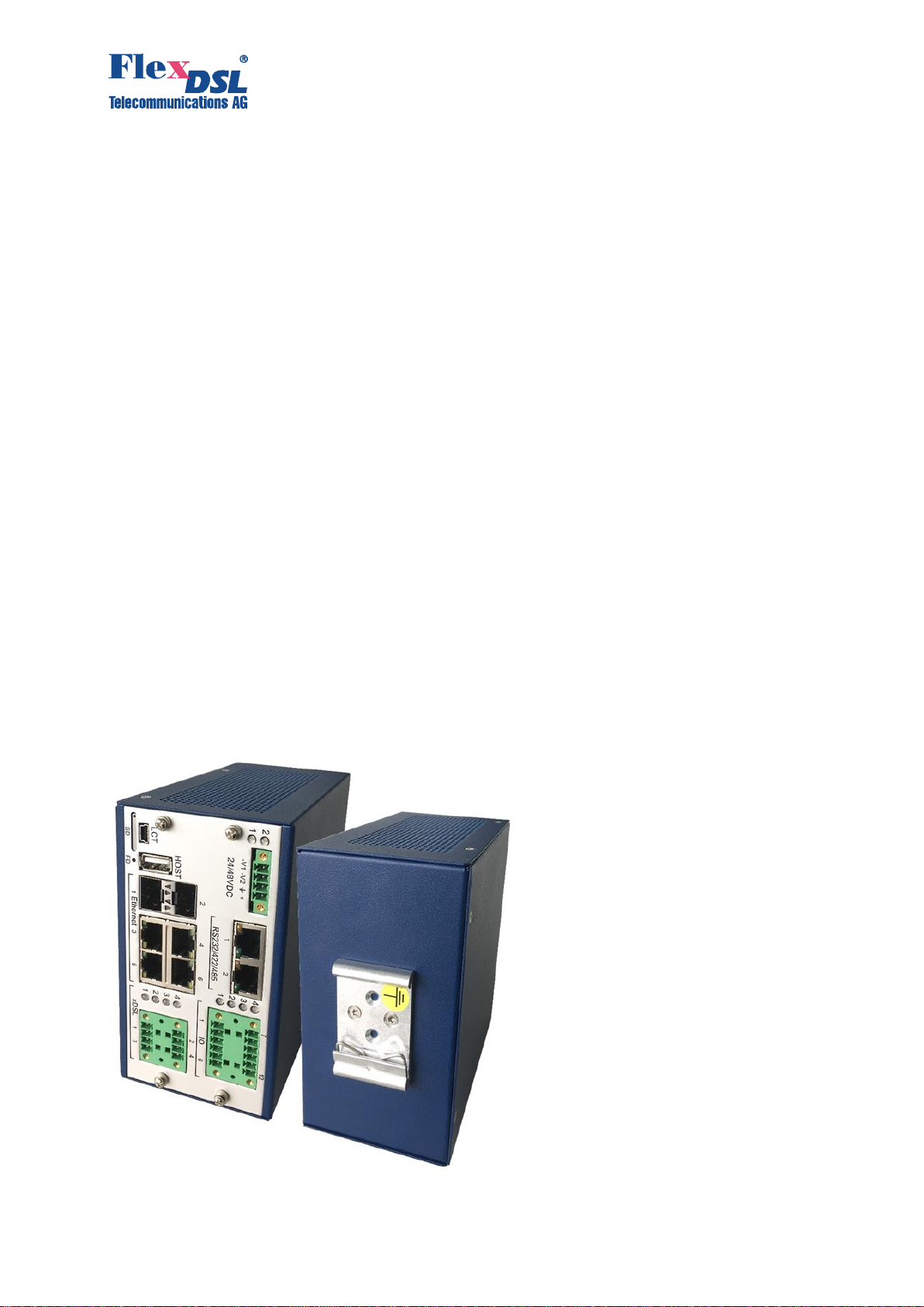
Figure 3-1. The GigaFlex DIN-rail SHDSL and Fiber model

Technical Description and Installation Manual GigaFlex
8
The following protocols are supported to grant an easy and secure access by a network
administrator:
•Local Command Line Interface (CLI) access over the Local Craft Terminal (LCT) with
USB or RS232.
•Remote Command Line Interface (CLI) access over Telnet or SSH.
•The Graphical User Interface (GUI) over HTTP or HTTPs.
•Simple Network Management Protocol: SNMPv1, V2c and V3.
3.2 LED Indicator and Connector Pin Assignment on Front Panel
The front panel for models without serial and IO interfaces is shown on Figure 3-2.
Figure 3-2. Front panel for models without serial and IO interfaces.
The models with serial and IO interfaces have a front panel as shown on Figure 3-3.
Figure 3-3. Front panel for models with serial and IO interfaces.
The front panel LED indicator behavior as well as the connector pin assignment are summarized
on the next two tables.
Following models:
•GF-RAIL2N-6Eth-24V,V26
•GF-RAIL4N-6Eth-24V,V36
•GF-RAIL4N-6EthP-24V,V46
Following models:
•GF-RAIL2N-6Eth-2I2O/2SER-24V,V21
•GF-RAIL2N-6Eth-2I2O/2SER-PoE-24V,V25
•GF-RAIL4N-6Eth-2I2O/2SER-24V,V31
•GF-RAIL4N-6Eth-2I2O/2SER-PoE-24V,V35
•GF-RAIL4N-6EthP-2I2O/2SER-24V,V41
•GF-RAIL4N-6EthP-2I2O/2SER-PoE-24V,V45

Technical Description and Installation Manual GigaFlex
9
Element
Description
Power LEDs
Two bicolor LEDs red/green representing -V1 and -V2 input voltages status
LED1
LED2
LED
Status
Device Status
Off
No input voltage detected
Green
Input voltage detected, No Alarm
Amber
Input voltage detected, Minor Alarm
Red
Input voltage detected, Major Alarm / Device Boot
Power
Connector
4-pin Phoenix Mini Combicon MC 1,5/4-GF-3,81 (female)
Pin No.
Signal
Description
1
-V1
Negative power supply terminal 1
2
-V2
Negative power supply terminal 2
3
FPE
Functional Protective Earth
4
+0V
Positive power supply terminal
Matching Type for the cable:
FK-MCP 1,5/ 4-STF-3,81
For AWG 16-26
Area 0.141.5 mm2or
Diameter 0.4-1.4 mm
Serial Interface
Two RS232/422/485 Serial Interfaces on RJ45
Pin No.
Signal Direction
from / to the Unit (DCE)
Corresponding DTE line
RS232 / RS485 full(RS422) / RS485 half
Contact
location
1
Out
RXD / Rx- / D-
2
Out
CTS / Rx+ / D+
3
In
TXD / Tx+ / nc
4
GND
5
GND
6
In
RTS / Tx- / nc
7
CC (cable connect)
8
GND
IO LEDs
Four bicolor red/green LEDs representing Input / Output status
LED
Numbe
r
IO
State
Color
Normal Input state
Closed
Open
1
In 1
Closed (current present)
Green
Red
Open (no current)
Red
Green
2
In 2
Shutdown
Off
Off
Configured, but no Network
Yellow
Yellow
3
Out 1
Normal
Green
Inverted
Red
4
Out 2
Shutdown
Off
Configured, but no Network
Yellow
IO Lines
Two Input and Two Output lines.
12-pin Phoenix Mini Combicon MCD 1,5/ 6-G1F-3,81 (female)
Pin No.
IO
Description
1
O
Output 1 normally open
2
O
Output 1 common
3
O
Output 1 normally closed
4
O
Output 2 normally open
5
O
Output 2 common
6
O
Output 2 normally closed
7
I
Input 1a
8
I
Input 1b
9
I
Input 2a
10
I
Input 2b
11
+3.3Vdc Power
12
GND
Matching Type for the cable:
FK-MCP 1,5/ 6-STF-3,81
For AWG 16-26
Area 0.141.5 mm2or
Diameter 0.4-1.4 mm
with 6 contacts
Technical Description and Installation Manual GigaFlex
10
Element
Description
SD
Slot for MicroSD card with Tray
LCT
USB Type Mini-B female connector for Console access
HOST
USB Type A female connector for Flash Stick
FD
Factory Default button
SFP
Two SFP cages for mini GBIC 1000Base-X modules
RJ45
Four 10/100/1000Base-TX Ethernet connectors with MDI/MDIX support
DSL LEDs
Four bicolor red/green LEDs representing DSL status
LED No.
LED Color
DSL Status
1
Off
DSL 1 in shutdown state
Red
DSL 1 Major Alarm
Red, blinking
DSL 1 training with remote end
Amber
DSL 1 Minor Alarm
Green, blinking
DSL 1 Physical Layer up, Data Layer down
Green
DSL 1 operates, no Alarm
2
Off
DSL 2 in shutdown state
Red
DSL 2 Major Alarm
Red, blinking
DSL 2 training with remote end
Amber
DSL 2 Minor Alarm
Green, blinking
DSL 2 Physical Layer up, Data Layer down
Green
DSL 2 operates, no Alarm
3
Off
DSL 3 in shutdown state
Red
DSL 3 Major Alarm
Red, blinking
DSL 3 training with remote end
Amber
DSL 3 Minor Alarm
Green, blinking
DSL 3 Physical Layer up, Data Layer down
Green
DSL 3 operates, no Alarm
4
Off
DSL 4 in shutdown state
Red
DSL 4 Major Alarm
Red, blinking
DSL 4 training with remote end
Amber
DSL 4 Minor Alarm
Green, blinking
DSL 4 Physical Layer up, Data Layer down
Green
DSL 4 operates, no Alarm
DSL Connector
Phoenix Mini Combicon MCD 1,5/4-G1F-3,81 Female, 8 pins.
Pin No.
Description
Contact location
1
SHDSL interface 2
2
SHDSL interface 2
3
SHDSL interface 4
4
SHDSL interface 4
5
SHDSL interface 1
6
SHDSL interface 1
7
SHDSL interface 3
8
SHDSL interface 3
Matching
Type for the
cable:
FK-MCP 1,5/ 4-STF-3,81
For AWG 16-26
Area 0.141.5 mm2or
Diameter 0.4-1.4 mm
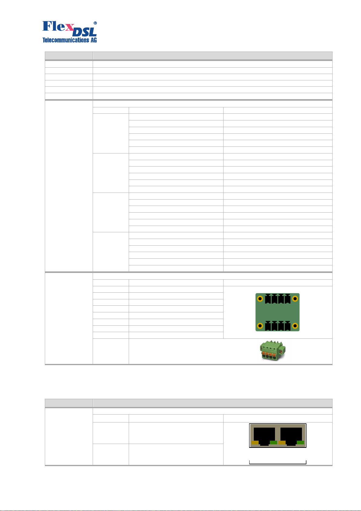
Table 3-1. Connectors and LEDs on the front panel.
The front panel contains several connectors with integrated LEDs:
Element
Description
Serial Interface
Two RJ45 Female connectors with integrated LEDs
LED
Description
Connector overview
Green
Act Rx or Act TX
Yellow
RTS or CTS High (RS232 Only)
Technical Description and Installation Manual GigaFlex
11
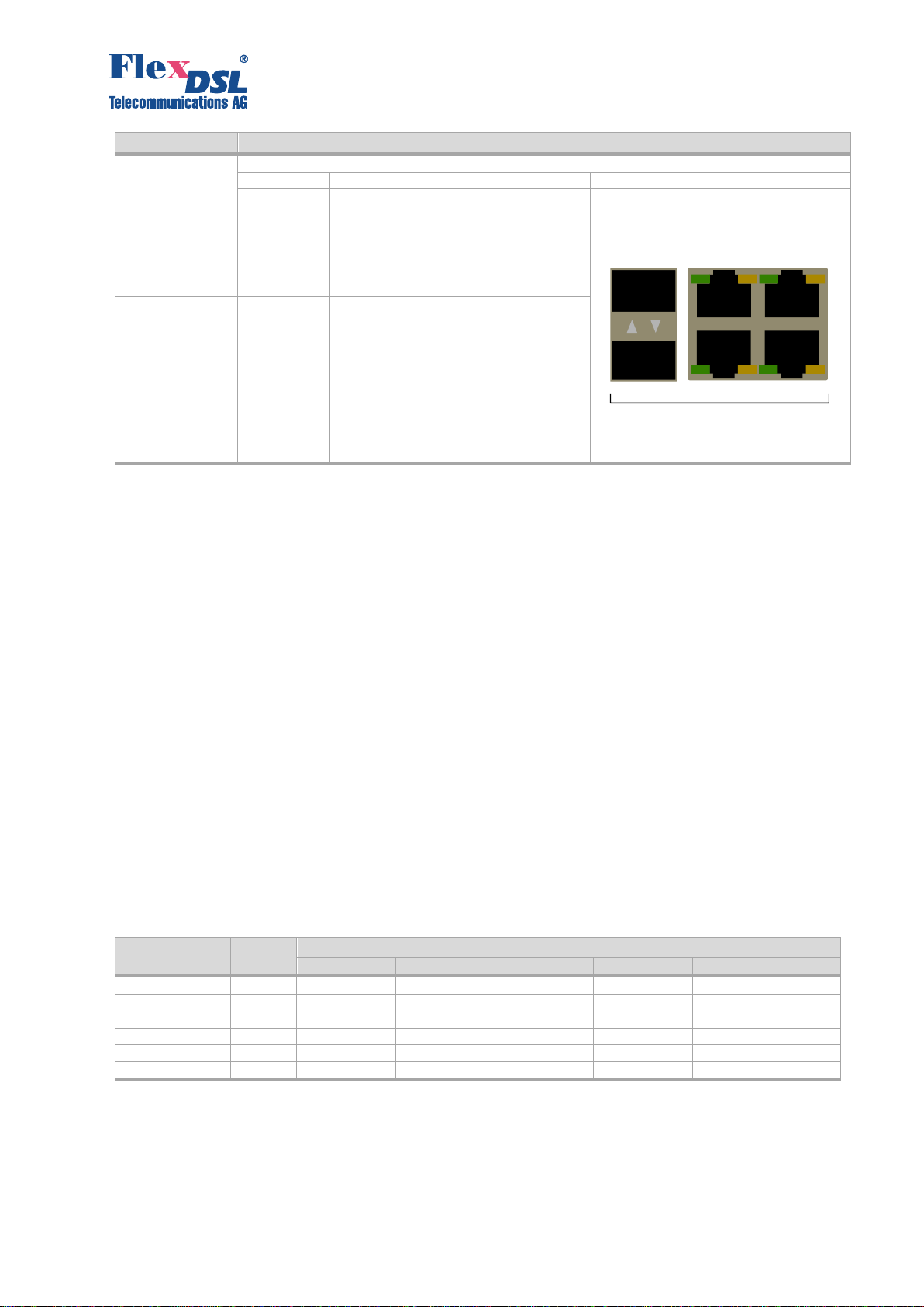
Element
Description
Gigabit Ethernet
LEDs
Four RJ45 Female connectors with integrated LEDs and two SFP cages
LED
Description
Connector overview
Green
Ethernet Act blinking:
340ms: 10H/10F
170ms: 100H/100F
84ms: 1000H/1000F
Yellow
100/1000Base-TX mode
SFP LEDs
1
Ethernet Act blinking for Port 1:
84ms: 1000H/1000F
2
Ethernet Act blinking for Port 2:
84ms: 1000H/1000F
Table 3-2. Integrated LEDs in Serial and Ethernet connectors.
3.3 GigaFlex Interface Description
3.3.1 SHDSL Interface
The GigaFlex models are available with 2 or 4 EFM-based SHDSL channels. Every channel can
operate independently or two and more interfaces can create a group. This process is called
bonding. Up to two bonding groups can be created. A single SHDSL channel or a group of
channels carry useful data traffic, called payload.
The EFM acronym means Ethernet on a First Mile. The EFM-based SHDSL transceiver operates
as PHY (Physical Layer of OSI Model). Upper Layers of OSI Model forms data flow that should
be transmitted over physical media. The SHDSL transceiver encodes data flow using TC-PAM
(Trellis-Codded Pulse Amplitude Modulation) and sends a data flow to the receiving end over a
twisted copper pair cable.
3.3.1.1 Modulation and Data Rates
The GigaFlex firmware supports TC-PAM4/8/16/32/64/128 modulations. Here the digit means the
number of levels in a signal pulse. Less number of levels means more distance between them.
More distance between the levels means more immunity to any kind of noise.
From the other hand, a modulation with low number of signal levels carries less data bits per
single pulse. This means that high data rates are not available for modulations with low number
of signal levels.
Modulation
Levels
Normal Mode
Extended Mode
Rate Min
Rate Max
Rate Min
Rate Max
Data Rate [kbit/s]
TC-PAM4
4
N/A
N/A
3
39
TC-PAM8
8
N/A
N/A
3
79
TC-PAM16
16
3
60
3
119
TC-PAM32
32
12
89
3
159
TC-PAM64
64
N/A
N/A
3
199
TC-PAM128
128
N/A
N/A
4
238
Table 3-3. Modulation, signal pulse levels and possible data rates.
The available data rate can be calculated as Rate*64, while formula Rate*64kbps + 8kbps will
calculate the speed on the wire, displayed in all statistical information of the GigaFlex models. As
Table 3-3, the available modulation and data rates are dependent on the operational
mode. The GigaFlex models support two modes of operation: Normal and Extended.

Technical Description and Installation Manual GigaFlex
12
•Normal Mode: only TC-PAM16 and TC-PAM32 modulations are supported.
•Extended Mode: offers all modulations from TC-PAM4 to TC-PAM128; extends maximum
possible data rates for TC-PAM16 and TC-PAM32 modulations.
3.3.1.2 SHDSL Annex A/B
The GigaFlex models support two PSD (Power Spectral Density) operation modes: Annex A and
Annex B. The Annex A is designed for the use in North America and has less impact on ADSL
systems if they work over neighbor pairs in the same cable. The output signal level is 13.5dBm
@ 135Ohm. The Annex B is designed for the use in Europe. The output signal level is 14.5dBm
@ 135Ohm.
3.3.1.3 Bonding Group
The GigaFlex models support up to two bonding groups. Any two from four SHDSL channels can
create bonding group 1, while other two channels can create bonding group 2. Three or
four independent channels can be added into bonding group as well. If bonding is not required,
four independent channels can work into four independent directions.
3.3.1.4 Master and Slave Mode
An SHDSL link can be created if two transceivers on it ends operate in different modes. It is
required that one transceiver is configured as Master and the other one as Slave. The GigaFlex
models can have up to four SHDSL transceivers. They all work independently and must be
configured separately. The available SHDSL settings are dependent on the Master/Slave
transceiver operation mode.
Parameter
Values for Master
Values for Slave
Bonding Group*
1, 2, no
1, 2, no
Master / Slave*
Master
Slave
Extended
disable, enable
disable, enable
PAM
If Extended disabled:
•16, 32
If Extended enabled:
•4, 8, 16, 32, 64, 128
auto
Baserate
If Extended off:
•
•89 for PAM32
•auto
If Extended on:
•238
auto
Annex
A, B
auto
*) All channels in one bonding group must be configured in the same way: either as a Master or as a Slave.
Table 3-4. Possible values for SHDSL-transceiver configuration parameters.
3.3.1.5 Topologies
3.3.1.5.1 Point-to-Point
A point-to-point connection is a direct connection between two devices. This can be realized with
just one or up to four copper pairs.
Figure 3-4. Point-to-point connection
14 pairs
ETH
ETH

Technical Description and Installation Manual GigaFlex
13
3.3.1.5.2 Point-to-Multipoint (Star Structure)
A point-to-multipoint connection is a connection of different places with a central point. This can
be realized with just one or multiple copper pairs.
Figure 3-5. Point-to-multipoint connection
3.3.1.5.3 Daisy Chain (Line Structure)
In a daisy chain you connect the devices in series and in each device, you can add/drop
Ethernet data. This can be realized with just one or multiple copper pairs.
Figure 3-6. Daisy chain connection
3.3.1.5.4 Ring Structure
A ring structure is mainly realized to have redundancy for the data transmission. It means when
a single copper connection fails, you still have a correct working application. For a ring structure
you must enable the RSTP protocol.
ETH
ETH
ETH
ETH
ETH
ETH
ETH
Technical Description and Installation Manual GigaFlex
14
Figure 3-7. Ring structure connection
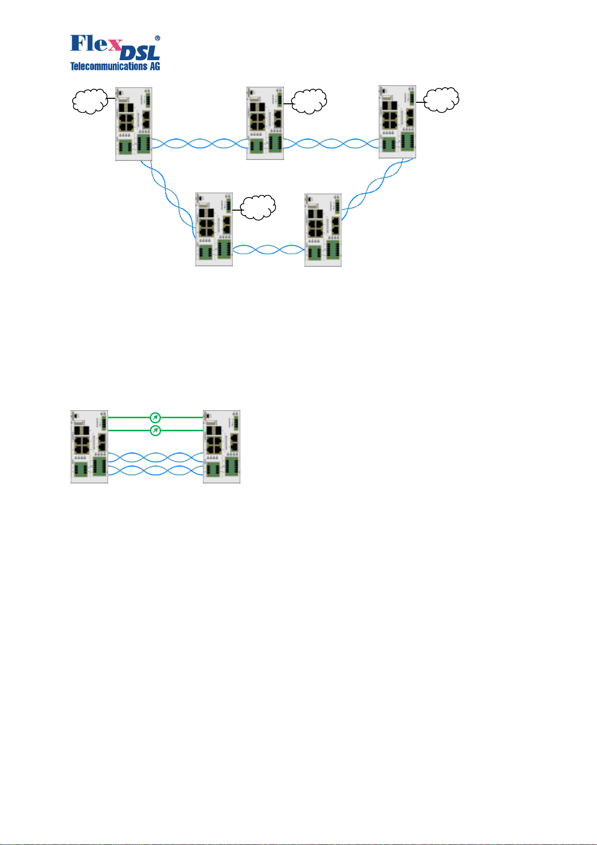
3.3.1.5.5 Interface Conversion and Redundancy
The GigaFlex models support redundant data connections. Redundancy can be achieved by
following ways:
•Data connection by multiple copper pairs
•Data connection by multiple fiber cables
•Data connection by copper and fiber
•Ring structures
Figure 3-8. Redundant connection with copper and fiber
3.3.2 Ethernet Interfaces
The GigaFlex models have ten Gigabit Ethernet interfaces. Six of them are located on the front
panel (2x SFP, 4x 10/100/1000Base-TX) and four are connected to the SHDSL ports because
the EFM chip operates as PHY. These ports are not visible but must be configured according to
desired application.
The Ethernet subsystem of the GigaFlex models is based on a high-performance SoC (System
on Chip) with 48 Gbps nonblocking switching capability. The SoC with its operation system
support various Layer 2 and Layer 3 protocols including:
•IEEE 802.1D:2004 MAC Bridges and Spanning Tree
•IEEE 802.1Q:2005 VLAN, MSTP, Multiple VLAN Registration (GVRP/MVRP)
•RFC 4330 SNTP
•RFC 3339 Date and Time on the Internet
•RFC 2865 RADIUS
•IEEE 802.1X:2004 Port-based Access Control
•IEEE 802.1AB Link Layer Discovery Protocol (LLDP)
•RFC 4303 IPsec
•RFC 4787 NAT
•RFC 2131 DHCP
•RFC 3046 DHCP Relay Agent
ETH
ETH
ETH
ETH

Technical Description and Installation Manual GigaFlex
15
•RFC 2453 RIPv2
•RFC 5798 VRRPv3
•RFC 3228 OSPF v 2
•RFC 5340 OSPF v 3
•RFC 3164 Syslog
•RFC 2819 RMON1
•RFC 4502 RMON2
•IGMP
Detailed configuration examples of selected protocols can be found in the GigaFlex Configuration
Manual.
3.3.2.1 Power Over Ethernet (PoE)
In some GigaFlex models the four 10/100/1000Base-TX Ethernet interfaces (RJ45) can generate
Power over Ethernet (PoE) according standard IEEE 802.3af, Mode A.. The maximum common
power output for all four Ethernet ports is 15 Watts.
Figure 3-9. 802.3af Po.
MDI to MDI-X crossover or an external power source for PoE functionality is possible by special
internal jumper settings. Please contact the manufacturer.
3.3.3 Serial Interface
The Serial interface of some GigaFlex models operates according to RS232/422/485 standards.
It transmits serial data over an IP-based Network using TCP or UDP messages. Point-to-Point
and Point-to-Multipoint topologies are supported.
The Serial interface has the following features:
•Rates: 150, 300, 600, 1200, 2400, 4800, 9600, 14400, 19200, 28800, 38400, 56000,
57600, 115200, 230400
•Number of data bits: 7, 8
•Number of stop bits:1, 1.5, 2
•Parity: None, Even, Odd
•Flow Control (RS232 only): CTS/RTS
Detailed configuration examples can be found in GigaFlex Configuration Manual.
3.3.4 Inputs and Outputs
Some GigaFlex models have 2 Inputs and 2 Outputs.
Input is a pair of contacts, connected to a current detector. If the current is present in the electric
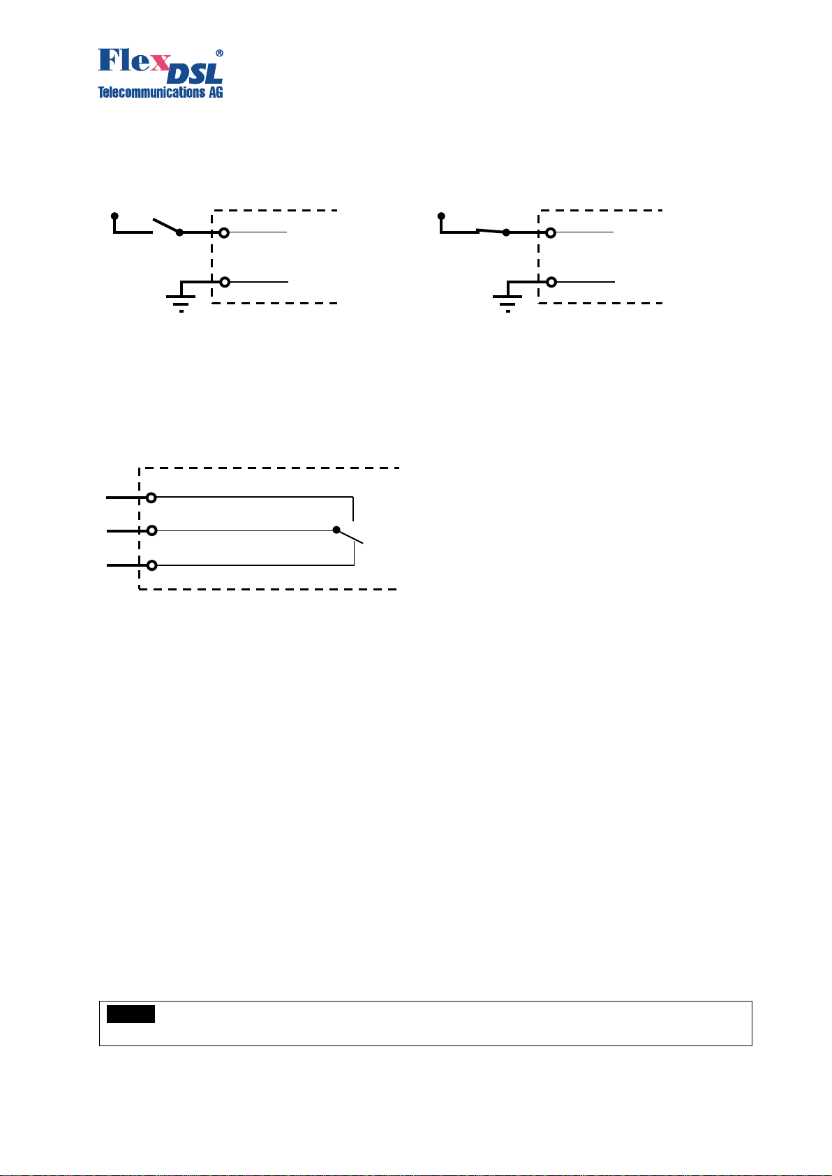
Technical Description and Installation Manual GigaFlex
16
circuit the Input switches its state to "closed". The Input changes its state into "open" if no current
detected in the electric circuit.
NO (normally open)
NC (normally closed)
Figure 3-10. Schematics of the inputs
Output is a pair of contacts (normally-open and normally-closed) and common wire connected to
a relay. The relay may stay either on "active" or in "inactive" state. Active state means that the
current passes through the relay coil and the common contact is connected to the normally-open
contact. Inactive state means that no current passes through relay coil and the common contact
is connected to the normally-closed one.
Figure 3-11. Schematic of the outputs
The IO status is transmitted over an IP-based channel either by UDP or by TCP messages. Point-
to-Point and Point-to-Multipoint network scenarios are supported.
Detailed configuration examples can be found in the GigaFlex Configuration Manual.
3.3.5 LCT USB Connector
The Local Craft Terminal (LCT) Type Mini-B USB connector allows local access to the command
line interface of the GigaFlex models. If connected to a PC, a new serial port will be available for
communication with the device. Start your favorite terminal emulation program and select new
serial interface to initiate configuration session.
3.3.6 SD Card and USB Host
A Micro SD card and USB flash stick can be used for saving and restoring configuration and
firmware. Check the configuration manual for details.
3.3.7 Factory Default Button, Default IP Address
It is possible to restore the default configuration of a unit if the Factory Default (FD) button will be
pressed and held for 15 seconds during boot process. The IP address will be overwritten to the
default IP address 192.168.0.235.
NOTE:
The FD Button erases startup configuration, so the factory default values will be
loaded. Please note that FD button does
Input a
Input b
+V
Input a
Input b
+V
Output Normally Open
Output Normally Closed
Output Common

Technical Description and Installation Manual GigaFlex
17
4 INSTALLATION
4.1 General Requirements
Before installing the device, read carefully the present manual. Take care about all warnings
inside this manual. Please note that the warrantee and free-of-charge repair will not be granted if
the device failed due to one of the following conditions:
a) Misuse and improper installation, including but not limited to:
- installation and useof theproduct ina conflictingway with the actualtechnical or safety
standards in the country where it is installed;
- uirements for power input
source;
- installation and operation in an environment that exceed defined climatic conditions of
the device.
b) Maintenance or repair performed by unauthorized service centers or persons.
c) Accidents, lighting strokes, flooding, water, fire, mud and dust, improper ventilation,
voltage drops and peaks, excessive moisture, excessive electro-magnetic impacts or
insects or any creatures have been penetrated the device causing its malfunction, as well
as other reasons laying beyond the manufacturer control and ing with
defined technical specification.
d) Improper transportation.
e) Defects of the system, where the device was integrated.
It is strictly prohibited:
a) to alter, remove or make illegible the serial number of the device;
b) to adapt, adjust or change the device in order to improve or to extend its functionality
without prior written consent of the manufacturer.
4.2 Unpacking the Unit
Before unpacking, check if the packaging is intact and if the model matches the purchase order
or contract.
Unpack the unit and make a visual inspection.
Write down model and serial number for internal records.
4.3 Mounting on DIN-rail
The GigaFlex models should be mounted on DIN-rail. The Figure 4-1 shows mounting options.
Figure 4-1. DIN-rail mounting options.

Technical Description and Installation Manual GigaFlex
18
Although the unit can be located either vertically or horizontally, the vertical position is preferred
because this enables a better airflow.
A comfort clip FG-RAIL-ComfortClip-Orion2/3 can be purchased separately. It simplifies the
device installation on a DIN-rail.
4.4 Connecting Power Input and Protective Ground
Connect the power,for example -24VDC, to the power input terminal as it is shown on Figure 4-2.
Please refer to Chapter 6.3 for Input Power Supply specification.
Figure 4-2. Power Connector
Be sure that the rail where you mount the GigaFlex device is proper connected to the Protective
Earth. If you are not sure about a proper Protective Earth connection through the DIN-rail
mechanics, please connect the Protective Earth to the corresponding connector on Figure 4 2.
-V1 and -V2 with a wire bridge.
The Unit will not show you an alarm indicating that one power supply input is not present.
4.5 Connecting Interface Cables
Connect all required interface cables. Use Table 3-1 as a reference for wiring.
Plug SFP modules and connect fiber cables.
Connect a PC with USB cable to the LCT jack and start a Terminal emulation program. The Serial
port settings are:
•Rate: 9600
•Bits: 8
•Parity: None
•Stop bits: 1
•Flow Control: Off
4.6 Power on the Device
Power on the device. The LEDs 1 and 2 on Figure 4-2 should be red during boot process.
Refer to the GigaFlex Configuration Manual for configuration steps and examples.

Technical Description and Installation Manual GigaFlex
19
5 MAINTENANCE
The GigaFlex models do not contain parts that require constant service or tuning during daily
operation. You should keep the enclosure clean and periodically check the quality of contacts in
jacks and in junctions.
We recommend that you perform the following measurements and keep the following records:
•SHDSL Speed and Signal to Noise ratio for every working link
•SFP DDM values: Attenuation
•Device Temperature
•CPU usage
The above-mentioned list may be increased according to the internal rules and norms of your
organization.

Technical Description and Installation Manual GigaFlex
20
6 TECHNICAL SPECIFICATION
6.1 Interfaces
6.1.1 SHDSL Interface
Specification:
ITU-T G.991.2-G.SHDSL, ITU-T G.991.2-G.shdsl.bis
IEEE 802.3ah (Ethernet in the First Mile)
Line Code:
TC-PAM16/32, Extended: TC-PAM4/8/64/128
Impedance:
135
Transmit Power:
13.5 (Annex A) or 14.5 (Annex B) dBm @ 135
Number of Pairs:
2 or 4
Bit Rate:
192 to 5704kbit/s, Extended: 128 to 15232kbit/s
Connector Type
Phoenix Mini Combicon MCD 1,5/4-G1F-3,81 Female, 8 pins.
Overvoltage Protection:
ITU-T Rec. K.20/K.21
6.1.2 1000Base-X Ethernet (SFP)
Standard:
IEEE-802.3
Data Rate:
1000Base-X Full Duplex
Protocols:
Layer 2, Layer 3
Connector Type:
SFP
6.1.3 10/100/1000Mbps Ethernet (GE)
Standard:
IEEE-802.3
Data Rate:
10/100Base-TX, Full/Half Duplex
1000Base-TX, Full Duplex
Protocols:
Layer 2, Layer 3
Signal Level:
Ethernet
MDI / MDI-X auto crossover:
Supported
Auto Negotiation:
Supported
Connector Type:
RJ45
6.1.4 Serial Interface
Specification:
RS-232/422/485
Number of Interfaces:
2
Bit Rate:
150, 300, 600, 1200, 2400, 4800, 9600, 14400, 19200, 28800, 38400,
56000, 57600, 115200, 230400 bps
Format:
Bits: 7, 8
Stop bits: 1/1.5/2
Parity: none/even/odd
Features:
RTS and CTS support for RS232
Termination on/off & Full/Half duplex for RS485
Connector Type:
RJ45, 8 pins
6.1.5 Digital Input / Output Interface (2I2O)
Inputs:
Number of Inputs:
2
Type:
Isolated, 2 lines / input, with rectifier bridge
Maximum Voltage:
Isolation:
Sampling rate:
Outputs:
Number of Outputs:
2
Type:
Isolated, 3 lines / relay output
Max Voltage:
Max Current:
This manual suits for next models
8
Table of contents


