Grease Guardian GGX75 User guide

Automatic Grease
Removal Unit
MANUFACTURED BY FM ENVIRONMENTAL
www.greaseguardian.com
MODELS GGX75 & GGX125 ISW
SYSTEM MANUAL 110/230 VAC
GGX 75 &125 ISW, 110/230VAC/V1

2
CONTENTS
Product Overview.......................... 4
Specication .................................. 5
Installation .................................. 6-7
Operation ..........................................8
Controller Settings....................... 9-13
General Maintance
..................... 14-15
Troubleshooting .................... 16-17
Wiring Diagrams .................................. 18
Compenents........................... 19-20
Warranty ................................. 21-22
Thank you for choosing the FM Environmental Grease Guardian X ISW
series. The ISW series (Internal Strainer with Wash system ) is a totally
engineered system for separating freeoating grease and oils from drain
water ows. The separated grease and oils are trapped within the stainless
steel tank and are automatically recovered by the system’s skimming
mechanism. Only the “cleaned” water is allowed to pass through the system
into the drainlines.
The ISW series is equipped with a removable strainer system to a remove
solid food waste. The system is also tted with an automatic wash system
for cleaning of key grease handling components.
GREASE GUARDIAN X 75/125 ISW OVERVIEW
APPENDICES
1. Application specic.
Controller setting . ................. 23
2. Cycle overview ....................... 24
3.
Wiring Diagram
........................ 25

3
The Grease Guardian 75/125 ISW can be used in a wide variety of
applications from restaurants and food processing operations to many
types of industrial operations. Uniquely the models within the this series are
designed to serve entire kitchen lines from a single central location, thus
guaranteeing 100% treatment of all source of fats, oils and greases.
In order to reduce staff maintenance the 75/125 series systems are
designed to work in conjunction with bulk oil containers to reduce
frequency of container replacement. The systems are also supplied with a
Building Management Connection as standard and can be further upgraded
on request to include a motion sensor system to monitor frequency of
maintenance and/or a high level oil container alarm system.

4
1. Ensure the unit is lled with water un3l the level is seen to stabilise at the
skimming drum/outlet level.
2. Check for any pipe leaks during the lling process. Ensure the plumber
seals up any leaks.
3. Ensure the power supply is installed and ready to be switched on by your
representaive upon arrival..
4. Never power up the unit without the Grease Guardian representative
present to check water level and settings.
5. Ensure an in-house senior staff member is appointed for system training
during the representative’s visit. Such a person should either be a
maintenance manager, or catering manager/chef. System training will
advise of:
a) daily and weekly maintenance tasks required for this system. Knowledge
acquired by the senior member will in turn allow delegation of system tasks to
other staff members during the system’s lifespan.
b) Weekly waste oils handling and service requirements for the system.
IMPORTANT CUSTOMER NOTICE
Prepare for commissioning by your market representative:
On completion of installation as described in this manual please ensure the
following steps are taken before arranging system commissioning:

5
PRODUCT DIMENSIONS & SPECIFICATIONS - ISW, 230 VAC
Casing Material 16 Gauge for GGX75.
14 Guage for GGX125.
AISI 304 Stainless Steel;
Bright nish
Time Control Progrmmable Logic
Controller with
programmable
4hr cycles and 7 day timer
Skimming 10 litres per hour
Solids transfer pump
rate (ow/head max)
n/a
Hot wash water system
operation requirements
Minimum 0.75 litres/s
@ 3-6 bar
(temp 40-60 degrees C)
Power supply 230V, 50Hz, 1 phase
Front view
Top view
Rear view
ISW
Model AB C D E F G Inlet
pipe
Outlet
pipe
GGX75 1100 545 257 457 595 420 315 110 110
GGX125 1500 620 275 457 595 500 385 110 110
ISW Model GGX75 GGX125
Hydraulic Flow 1/sec 4.75 7.9
Grease Retention
Capacity litres 80 138
Net system weight (kg) 95 117
System Weight full
(in operation) kg 272 411
Electrical load (max) 4.8A 9.1A
All dimensions in mm

6
INSTALLATION
Locate Internally
Do not install this system externally unless a weather proof shelter is used.
Ensure the ambient temperature is maintained within a range of 10 to 35
degrees C (32 - 95 F). This is to ensure both electrical safety and to prevent
cooling of skimmed grease on the grease outlet channel. Warranty is void
unless these conditions are met.
Replacing an older grease trap?
It is imperative to clean drain lines of blockages from build up before
installing this system, particularly when replacing older grease traps.
Unit Positioning
To plan a suitable position for the GGX rst refer to “Product Dimensions
and Specication” page in this manual to check available clearances.
Position the unit as close as possible to the xtures it is serving to minimize
grease build-up in the piping. If the system is to be mounted on a frame
ensure the additional height of frame is added to the standard table
specication height.
If the unit’s position is directly oor mounted, ensure that the oor is pre-
lacquered and that the unit base is sealed to the oor around its perimeter
by using an approved silicone sealant. Lacquering of the oor generally also
ensure that any oils spills are easily cleaned later in the maintenance period.
Consider installing oor gullies in the location to receive spillages.

7
Excluded Kitchen Fixtures
Do not connect the system to food grinders, potato peelers or waste
disposal units. Such installations will void Grease Guardian's Warranty.
Inlet piping
Drain piping from the sinks/oven should be 2 inch Ø (50mm) minimum.
Ensure that a fall of 1/3” inches per foot (1:40) is used and keep the inlet
pipe as short as possible to avoid grease build-up before it reaches the unit.
If the unit is serving more than one xture ensure that the respective drain
pipes and joined in a T-piece before they enter the unit piping. Install “P”
or “U” Traps before inlet on sinks as normal. A Rubber Couplings with screw
clasp are included.
Outlet piping
Keep the outlet piping as straight as possible, only use"sweep"connections
and minimize the number of bends used. Do not reduce the size of the pipe
used in the outlet, keep the outlet piping as short as possible and do not
install any “P” or “U” traps (the units has an in-built internal gas trap). If the
unit overows during operation the problem normally lies with the size and
layout of the outlet piping which is not t to take the full ow freely.
Flow controller
If your plumbing code requires a vertical type ow regulator, and for
high head height applications (over 6 ft, such as when installing units in
basements) and to comply with certain requirements, a proper ow control
device with air intake must be tted on the inlet piping. Suitable air intake
pipework should be routed to the top of this component and connected to
a vented waste stack within the building. Note that if the Grease Guardian
is serving multiple xtures, some plumbing codes ask that each xture is
equipped with its own ow control device.
Flow Control X75: Endura XL 4044275A
Flow Control X125: not yet available
Inlet and Outlet piping connections
Rubber Couplings with screw clasps are included.
Automatic spray wash
Each Grease Guardian ISW unit comes complete with two automatic wash
spray bars, located in the main grease collection chamber. A hot water
supply is to be plumbed to the water inlet connection on the manifold at

8
the back of the unit. The hot water supply should preferably be ltered to
avoid any particles from entering the solenoid valves provided. The plumber
has to ensure that any plumbing of the tap water supply to the manifold
conforms with the local plumbing codes in particular to the provision of any
backow prevention devices, assemblies and methods to be used.
Single Phase Connection
The power cord of the unit is to be hardwired directly to a dedicated mains
outlet rated to handle electrical loads as described in the specications
table of this manual. Hardwired outlet must be tted with a double pole
switch. CAUTION: to provide continued protection against risk of electric
shock, connect to properly grounded outlets only. All electrical work must
be carried out by a qualied electrician.
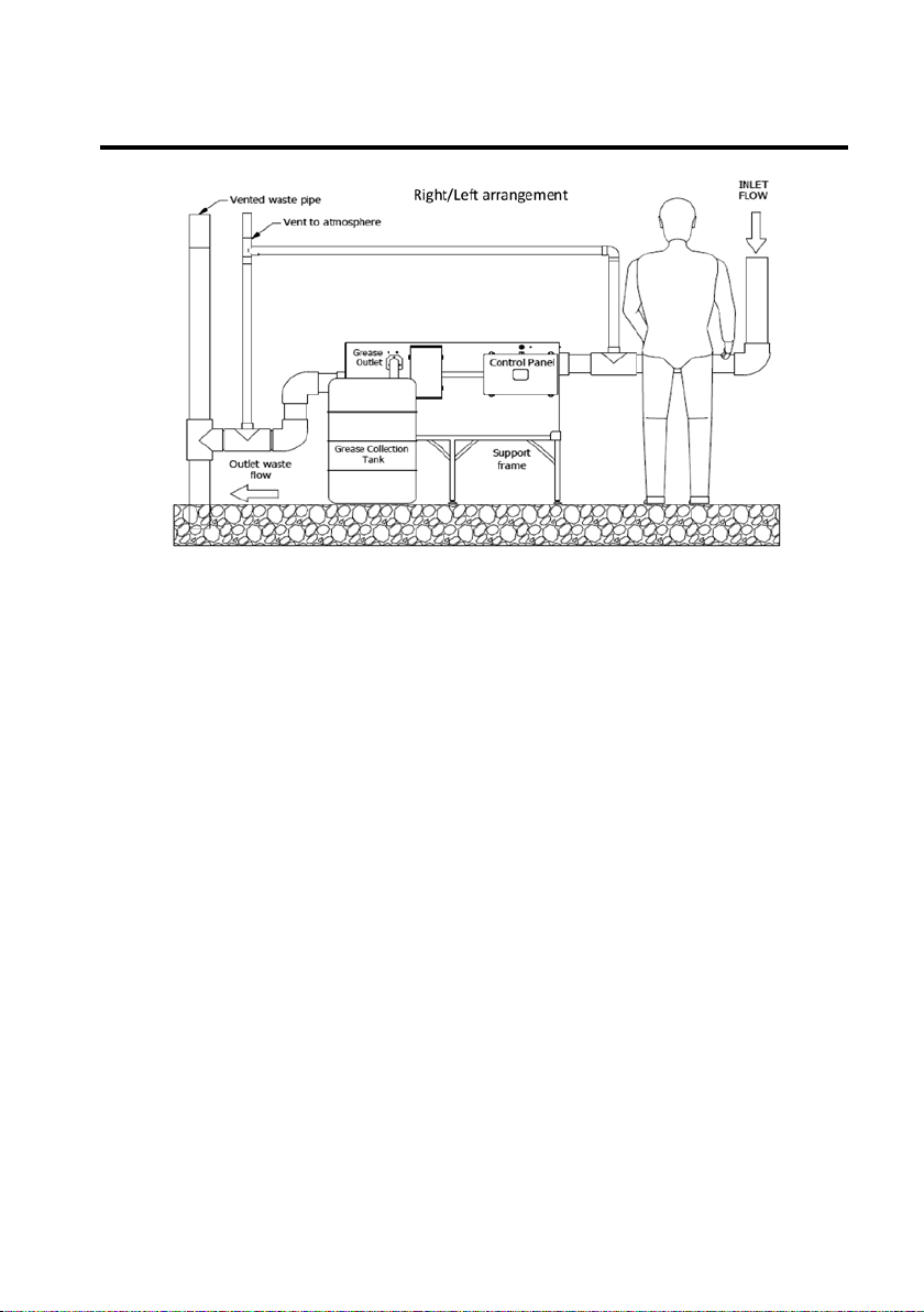
Venting
For the inlet piping, a pipe vent (or code approved air admitance valve)
which is at least 1/2 the inlet pipe diameter should be connected. An
additional pipe vent (or code approved air admitance valve) which is at least
1/2 the outlet pipe diameter should be connected to the outlet pipe of
the system and located as close as possible to the Grease Guardian outlet
connection. It is always preferable to have vent pipes used for each Grease
Guardian system connected to one common vent pipe and venting directly
to atmosphere rather than combining these with other waste pipe vents.
This method eliminates the possibility that odors from other other xtures
making their way back into the Grease Guardian unit.
Room ventilation
Odors will be minimised via the correct venting method above. However
air extraction fan systems should be installed in more conned locations of
less than 4m3. Such a system should also be installed in ANY location where
personnel are working close to the System location.
Operating Temperature
Ofcial room temperature range for safe electrical operation of this system
as required under the appropriate UL standard is between 0 and 35 degrees
C (32 - 95 F). However for optimal grease removal the room temperature
should be maintained at 10 and 35 degrees (50 - 95 F). This will reduce the
risk of grease solidifying on the skimming mechanisms.
All instructions and drawings provided in this booklet are for reference only.
The unit provided is tobe installed in compliance with the local legislation,
regulation and codes. Installation by a qualied plumber knowledgeable with
the local plumbing code is necessary.

9
DESCRIPTION OF OPERATION
In normal operation, the unit will require minimal operator input. The system
has a number of automaic functions as described below, with the main manual
task being limited to the removal of the collected grease from the colletion
tank.
Flow from the kitchen enters the inlet side of the unit.
Solids accumulate inside the manual strainer within the rst compartment.
Lighter free oating grease is allowed to pass through the strainer mesh
and into the grease collection compartment.
The grease that passes to the grease collection chamber is periodically
skimmed out of the unit by a rotating skimming drum The skimmed
grease passes to a receiving waste container.
The rst automatic spray bar activates for short bursts during the
skimming cycle to aid movement of the grease towards the skimming
drum. An additional automatic spray bar located nearer the skimming
drum washes the skimming blade and collection channel after the
skimming cycle has completed. Finally the claried portion of water
exits together via the nal outlet at the rear of the unit.
A
B
C
D
E

10
• The unit requires both weekly user maintenance and also Quarterly service
by approved engineer to avoid performance issues.
• Do not use Hazardous detergents to clean unit, and do not pour detergents
or chemicals directly into the unit.
• The unit is designed to trap and remove free oating grease oils and fats
only.
• To help ensuring the highest grease removal efciency, reduce solid food
waste by installing primary strainers or scraping waste into bins
• The unit is provided with an automatic solids transfer system to provide
protection from solid food waste build up in the unit when properly
maintained.
• Consult your supplier in the event of increased loadings to the Grease
Guardian.
• Do not connect food grinders, potato peelers and/or waste disposal units
or similar devices upstream of the Grease Guardian.
ENSURING OPTIMAL SYSTEM EFFICIENCY

11
HOME SCREEN/START SCREEN
The Home Screen is shown onLeft.
The following notications are permanently
displayed in the Home Screen.
a. PLC program version on top leS
b. Time of Day on the top right.
CYCLE ON ZONES SCREEN
Press "A" from the Home screen. The 4 main ON
zone periods are displayed (T-zones). Should an
alternative menu appear then re-press "A" until
the correct screen is called up.
Each zone is of a xed 4 hour duration. To set
any zone to active press the corresponding keys
indicated: "B", "-" , "+", "OK". The word "SET"
displays for any active zone. To deactivate a zone
simply re-press the corresponding key.
CONTROLLER SETTINGS - SETTING MAIN CYCLE
CYCLE DURATION SCREEN
Pressing "A" again will call up the "CYCLE
DURATION" display. This display sets separate
ON time durations for the heater and skim motor
components within any T1-T4 zone. A single
value comprises of 15 minutes time duration,
10 minutes ON/5minutes pause. Note that the
"Heater" values must be >= "motor" values
or the controller will display the "INVALID
PROGRAM" Alert. (see User Alerts page)
To adjust the value displayed use "-" or "+" to
navigate to the HEAT value. Then press "OK"
to lock on to the value. Next use "-" or "+" to
increase or decrease the value. Conrm the
setting by pressing "OK" again. Next move the
cursor using "-" or "+" to the Motor Step value
and repeat the setting procedure, conrming
setting with "OK"

12
ADVANCED SKIMMER DURATION SCREEN
(keep as factory default in most applications)
Pressing "A" again will next call up the "SKIM
DURATION" display. This display further
optimises the ON/OFF duration for the skim
motor component. The default is 600 secs ON
(10 mins) and 300 seconds OFF (5 mins). To
adjust: use keys "-" or "+" to navigate to the
ON value. Then press "OK" to lock on to the
value. Next use "-" or "+" again to increase or
decrease the value.
BLOWER SETTING SCREEN
Pressing "A" again will call up the"BLOWER
SETTINGS" display. For systems tted with a
blower system, this display sets time limits for air
ow to the submerged aeration bar. To adjust:
use keys "-" or "+" to navigate to the ON value.
Then press "OK" to lock on to the value. Next
use "-" or "+" again to increase or decrease
the value. Conrm the setting by pressing "OK"
again. Next move the cursor using "-" or "+" to
the OFF value and repeat the setting procedure,
conrming settings with "OK".
SURFACE WASH SETTING SCREEN
Pressing "A" again will call up the "SURFACE
WASH SETTINGS" display. Surface wash is
a standard feature in all ISW and AST units
required to separate oating sediment form
surface grease. The display sets time limits for
water owing to the spray bar. To adjust: use
keys "-" or "+" to navigate to the ON value.
Then press "OK" to lock on to the value. Next
use "-" or "+" again to increase or decrease
the value. Conrm the setting by pressing "OK"
again. Next move the cursor using "-" or"+" to
the OFF value and repeat the setting procedure,
conrming settings with "OK".

13
DRUM WASH SETTING SCREEN
Pressing "A" again will call up the "DRUM
WASH SETTINGS" display. This is a standard
feature in all ISW and AST units. This feature
cleans the skim drum of any debris and is
automatically activated x 1 time only, at the
end of an active T zone. The display controls
the duration of water ow to the spray bar. To
adjust: press "OK" to lock on to the duration
value. Next use "-" or "+" again to increase or
decrease the seconds value. Conrm the setting
by pressing "OK" again.
HEATER OFF MODE
In locations where water temperature from
drainage appliances is sufciently hot there
is less of a requirement to use the Grease
Guardian heater. To preserve the heater element
and reduce energy costs, the heater can be
disengaged. This is achieved by pressing and
holding key "B" for 10 seconds when in the
Home screen. The heater is shut off for any
future cycles. This setting is maintained even
after a PLC power down/restart. To reengage
the heater at any time re-press and hold "B" for
for 10 seconds when in the Home screen.
COMMISSIONED ON (DATE) SCREEN
Press "OK" and "B" together from the Home
screen. The COMMISSIONED ON display should
show. If an alternative menu shows, then
re-press key "B" only until the screen left is
called up.
The "COMMISSIONED ON" display simply
logs the commissioning date for the Grease
Guardian for general reference. To set this at
commissioning, use "-" or "+" to navigate to the
day, month, or year value as required. Then press
"OK" to lock on to the value. Next use "-" or
"+" again to increase or decrease the value.
Conrm the setting by pressing "OK" again
in each case, before moving to the next value.
Conrm se;ngs with "OK" before returning to
Home Screen by pressing "ESC"

14
CONTROLLER SETTINGS - EVENT LOGGING
LAST SERVICED ON (DATE) SCREEN
Press "OK" and "B" together from the Home
screen. Re-press key "B" only until the screen left
is called up.
The "SERVICED LAST" display simply logs the
last service of the Grease Guardian for future
reference. To adjust, use "-" or "+" to navigate
to the day, month, or year value as required.
Then press "OK" to lock on to the value. Next
use "-" or "+" again to increase or decrease
the value. Conrm the setting by pressing
"OK" again in each case, before moving to the
next value. Conrm settings with "OK" before
returning to Home Screen by pressing "ESC"
SERVICE INTERVAL REMINDER SCREEN
The "SERVICE INTERVAL" display is a control
menu that sets the interval in months for
the "service due" reminder. For full safety
compliance the recommended setting is 3
months
To access press "OK" and "B" together from the
Home screen. Re-press key "B" only until the
screen left is called up.
All settings above are battery backed up in event of disconnection or a power outage

15
CONTROLLER SETTINGS - USER ALERTS
AUTOMATIC TEST OF COMPONENTS
On power up, the controller will run the
automatic TEST sequence and the Home screen
displays each component in sequence for an
"ON" duration of 4 seconds. FOR ISW series
units, the TEST sequence is: HEAT TEST >
SKIMMER TEST > SURFACE WASH > DRUM
WASH > SCREEN WASH > BLOWER > END.
Later the TEST can be reactivated by pressing
"-" or "+" together. Any TEST can be cancelled
mid-test by pressing "ESC". Note that the
internal pump is not tested via this controller,
but via a separate panel mounted TEST button
LID OFF ALERT
The display ashes a LID OFF alert if the main
Grease Guardian tank lid is removed.
Additionally if the unit is in a cycle, the heater
and motor components are shut down to allow
safe access inside the tank if required.
PIR REMOTE SENSOR (Where Supplied)
ISW and AST series units.
This device registers inactivity near the unit
exceeds 7 days. It then ashes a maintenance
reminder. The feature is also linked to the
BMS output on the controller. The message
is re-set for a further 7 days when activity is
detected again. Note this sensor version does
not interrupt any cycle operations and is for
information only.

16
INVALID PROGRAM ALERT
This message will ash within the Cycle Duration
Menu if there is an attempt to set the skim motor
values to greater than the heater values. Any
cycle is prevented as a result, as there is a risk
of insufcient grease liquefaction in the pre-
warming period and also an increase chance of
water being skimmed. To correct this issue the
Heater value must be set either to the same
value as the motor or higher value. The values
are normally advised by your representative at
commissioning.
IN CYCLE ALERT
This message ashes at all stages of an active
heater/motor cycle including the pause periods
within a cycle. The message terminates after any
skimming cycle completes
SERVICE DUE ALERT
If a general service visit is not carried out on the
date due this message will ash to indicate that
a service is required. While the unit's operation is
unaffected this alert it does require cancellation
after the service. This is done usually by an
engineer. If the unit has been recently serviced
and the message still shows, it can be cancelled
by entering the "SERVICE INTERVAL" display
from Home screen, ("OK" & "B" then nd menu
using "B") Press and hold the "A" key for 5
seconds to cancel, before pressing ESC to return
to thr home screen

17
DAILY
Check and remove the solids strainer and
dispose of contents to food waste bin
MAINTENANCE MAIN TASKS
WEEKLY
Remove the grease from the grease
cotainer (or barrel if supplied)
and dispose of in correct manner
accordance with local oil waste codes
Outsourced Servicing
Quarterly Inspec"on and Pump Out
carried out by a licensed waste collection
company with prior training on the GGX
product. Also the unit timer control and
components are to be inspected and
tested during each service visit. Any
wear and tear parts are to be replaced if
necessary.
Daily/Weekly/Monthly user maintenance
1
2
3
SEE OVERLEAF FOR FULL OVERVIEW OF CHECKS

18
MAINTENANCE IN DETAIL
1. In House Maintenance Of Your System
Minimal Maintenance
• Check the Internal Solids Strainer daily. Remove and dispose of contents
to foodwaste bin.
• Check the grease collection vessel daily - standard container, or weekly
if supplied with barrel tomonitor remaining capacity. This should be
carried out particularly in early stages of system use.
• Check that there are no obstructions on the grease channel and exit hose
weekly.
Additional spot checks in cases of under-performance/low skimming:
• Check that the spray wash cycles in the skimming chamber activate
regularly and that the bar nozzles are not obstructed
• Perform a PLC program test to conrm that all the components are
func3oning properly. This can be carried out by switching off at mains
and repowering up. The test starts automatically on power up. (All
settings battery backed up)
2. OUTSOURCED SERVICING QUARTERLY
(90 DAYS.)
Quarterly Inspection and Pump Out
To guarantee maximum efciency the unit should be inspected mechanically
and pumped out quarterly throughout the year. This is to be carried out by a
licensed waste collection company with prior training on the GGX product.
During such a service the main lid is removed and the internal chamber walls are
power/ steam cleaned. To allow transfer of water from the grease chamber to
the pump chamber a ap needs to be opened by pulling the divider vertically
upwards. Both chambers are then pumped out completely with a wet vacuum.
The unit is relled using the water ow from the sink. The unit timer control and
components are to be inspected and tested during each service visit. Any wear
and tear parts are to be replaced if necessary.

19
TROUBLESHOOTING
PROBLEM: Unit not removing grease
Is the power on?
Check that the power is on and that the time control is set correctly. If the
power is being supplied and there is no display check fuses or contact
your supplier.
Is wiper blade and wiper slot clean?
Open the main lid and clean any build-up present on the wiper blade assembly.
Ensure the wiper blade is bolted in place and makes proper contact with
skimming drum. Ensure that the automatic wash cycle of the wiper blade is
functioning by simulating it’s operation through the Test mode of the controller.
Check the cycle status
First check that “IN CYCLE” is displayed at the start of a cycle. Later in the cycle
the skimming motor should be audible. Should there be no skimmed grease
emerging during the cycle a further test can be conducted by entering TEST
mode as described earlier in this manual. With the main lid removed and with
hands kept clear of the skimming drum use this feature to check that the
motor is running during the TEST mode.
Inadequate Heating?
If the drum is turning but grease is not being removed it may not be dissolving
or separating out. If the grease appears hard or crusted, the GGX heater may
require inspection or replacement as the grease may not be dissolving. The unit
might require emptying and cleaning from sludge.
Emulsied/starchy foods, or soaping problems in the waste ow?
If the surface grease layer is liquid or foam-like in appearance and grease
is still not skimming out then it may contain high volumes of dairy waste
such as mayonnaise, or starchy waste from rice or pasta. Ensure to reduce
volumes of this waste entering the GGX unit. Ensure that the automatic
rinse system is being activated. Also ensure to reduce the use of aggressive
detergents and do not dispose any bleaching agents into the unit. Only
neutral hand washable detergents should be used atthe sink. Heavy oven
cleaning agents can adversely affect performance if ovens are connected to
GGX.

20
Check the main Lid and Lid-switch
The unit will not operate with the lid removed. This is a safety feature.
With the exception of some maintenance tasks the lid must be fastened in
place correctly at all times so that the switch is making contact at all times. If
this is not the case then the controller display will blink a LID OFF message.
If the message continues to show but the lid seems secure then there may
be a fault with the lid switch or magnet.
PROBLEM: Standing water
inside the grease collection container
Check Timer Settings
The unit will skim off water if there is little or no grease left in the main tank.
Excessive water will typically settle below the grease layer in the collector. Check
the timer settings for excessive ON times. The ON time should be scaled back
to reduce water being skimmed into the collector.
PROBLEM: Surge Water in
grease container and/or spillages onto oor
Is either the outlet or the follow on pipework blocked?
In rare cases an obstructed exit from the unit may lead to level rises in the
main tank which can spill into the grease collector suddenly and in turn onto
the oor, if left unchecked. Ensure that there are no drain line blockages
downstream from the unit. Ensure the unit is pumped out at least once
quarterly so that sludge does not obstruct the passageways within the main
tank.
Ensure the outlet pipe-work from the Grease Guardian is at a gravity fall of 1:40
minimum. Any restrictions in the outlet pipe due to a number of bends and
T-pieces before it reaches the outlet end should be reduced. Ensure the outlet
pipes from the unit are not smaller than the outlet pipe connection on the unit.
Larger pipe sizes are more effective in prevent ow restrictions or obstructions.
Is the system ow rate properly matched against all xtures
connected?
Ensure that the water ow to the unit does not exceed its rated ow in
gallons per minute.
This manual suits for next models
1
Table of contents
Other Grease Guardian Industrial Equipment manuals