enware EMF305M Installation and operating instructions

TOUCH-ACTIVATED URINAL FLUSHING
SYSTEM - SLIM BUTTON (DUCT ACCESS)
Installation & Maintenance Instructions
EMF305M
Call 1300 369 273
www.enware.com
Enware Australia Pty Limited
9 Endeavour Rd Caringbah NSW 2229 Australia
Ph: 02 8536 4000 Fax: 02 8556 4055
I00015 - AUG12

Version: Jul 13
Call 1300 369 273
www.enware.com
Enware Australia Pty Limited
9 Endeavour Rd Caringbah NSW 2229 Australia
Ph: 02 8536 4000 Fax: 02 8556 4055
Enware’s urinal flushing systems provide a neat and reliable
flushing solution using piezoelectric technology particularly
suited for public access applications.
Electronic Flush Valve for urinals, activated by a piezo button
that is powered by mains power. Semi concealed installation.
Shut off valve and filter included.
FEATURES
• Piezo touch button control
• Stylish dress ring style fascia
• Mains power 24V
• 3 Star water efficiency rating*
• 1-year warranty
OPTIONS available on request
• Sentinel Flushing - Every 12 or 24 hours
Water Supply 350 kPa
Connection Inlet - ½” BSP (15mm)
Minimum Water Supply Line Size ¾” (20mm)
Mains Powered 24V AC transformer
Technical Information
WATER
RATING
A joint government and industry program
Licence No. 0058
For more information and to compare
products,refer to:
www.waterrating.gov.au
Water Consumption
litres per flush per stall
2
The more
stars the more
water efficient
ATS5200.030
CofC 60042
AGA
ATS 5200.020
C of C 40116
Global-Mark
Touch-Activated Urinal Flushing System
- Slim Button (Rear Access)
EMF305M
Product Codes
EMF305M-3 WELS 3 Star rated*
120
40
30C/C
110C/C
Ø5 TYP
Ø50
58
77
185(REF)
30
CUT OUT IN WALL
95(REF)
1/2" FEMALE
1/2" BSP MALE
175MAX
48
47

Before proceeding with installation ensure all operating & dimensional specifications are suitable for the intended installation.
1.1 INSTALLATION COMPLIANCE REQUIREMENTS
Enware product’s must be installed in accordance with
AS/NZS 3500.1 & AS/NZS3500.2 – Plumbing and Drainage,
the Plumbing Code of Australia as well as imposed Local and
State / Territory Legislative requirements and the manufacturers
instructions.
The following clauses must be observed for a compliant installation
and correct operation of Enware tapware:
Water Services
Plumbing Code of Australia:
Part B1 Cold Water Services
AS / NZS 3500.1-2003 Water Services;
• Section 3.3.2 Pressure at outlets (min 200kPa is required for
valve to operate)
• Section 3.3.4 Max. pressure within buildings (500kPa
operating)
• Section 3.4 Velocity Requirement (Max 3.0m/s)
• Section 16 Testing and Commissioning; Flushing,
Hydrostatic testing, cleaning & disinfection of water services.
NOTE: Enware’s WC flushing units have Watermark License to
ATS5200.020 (For Flushing Valves for Water Closets and Urinals -
For use with Mains Supply), ATS5200.030 (Solenoid Valves) and
WELS registered to AS/NZS 6400
IMPORTANT TECHNICAL REQUIREMENTS
To ensure that the unit works correctly, it is important to ensure that
the site and location of installation meets the hydraulic requirements
of AS/NZS 3500.1. Also there must be:
• Minimum 20mm copper supply line for 1 stall or up to
450mm wall space. 600mm of wall space may require
25mm supply
• Minimum 200kPa for valve to operate
NOTE: WELS Flush Volume only achieved at 350kPa
• No more than 1 valve per urinal OR 600mm wall space
• Flush valve must be no more than 2m above ground level
• Flush valve should be installed min 300mm above wall
hung urinal and 450mm above continuous wall urinals
Pipe work to the valve fixture must be sized according to water
service rule calculations and simultaneous demand requirements.
To ensure that the pipeline reticulation system for the valve is
designed correctly for the satisfactory performance of the valve
a Hydraulic services Consultant and/or Engineer (or other
personnel appropriately qualified in hydraulic services design) must
be engaged.
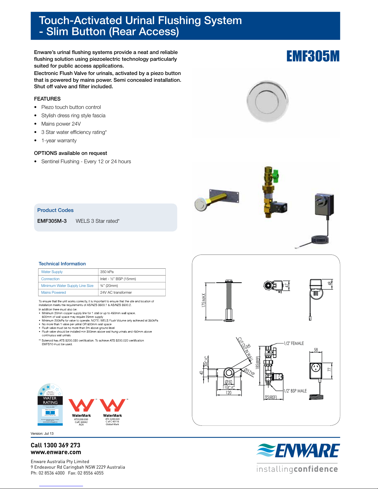
1.2 INSTALLATION INSTRUCTIONS
1. Separate parts from packaging & check each part
(figure 2.1). Parts will separate as shown in figure 1.2. Pay
attention to the different models variations. Make sure all parts
are accounted for before discarding any packaging material.
If any parts are missing, do not attempt to install your flushing
system until missing parts are obtained.
2. Flush water supply lines thoroughly before installing the flush
valve. Do not allow dirt, Teflon tape or metal particles to enter the
unit.
3. Shut off water supply and ensure shut off valve is closed
on flushing system.
4. Decide on appropriate location combining piezo operation and
valve placement. Install height of between 1-1.5m recommended
for piezo placement.
5. Cut a 30mm hole in the wall for piezo assembly and an
appropriate gap in pipe work in which to fix the valve.
(FIGURE 1.1)
Note: Note: 20mm (min) inlet pipe with 1/2” BSP (male) adaptor
required for install.
Note: piezo can be installed away from valve box where
necessary, i.e. flush valve in wall cavity with activation on different
wall. Extensions can be purchased if required. AS3500.1
requirements are still required to be met.
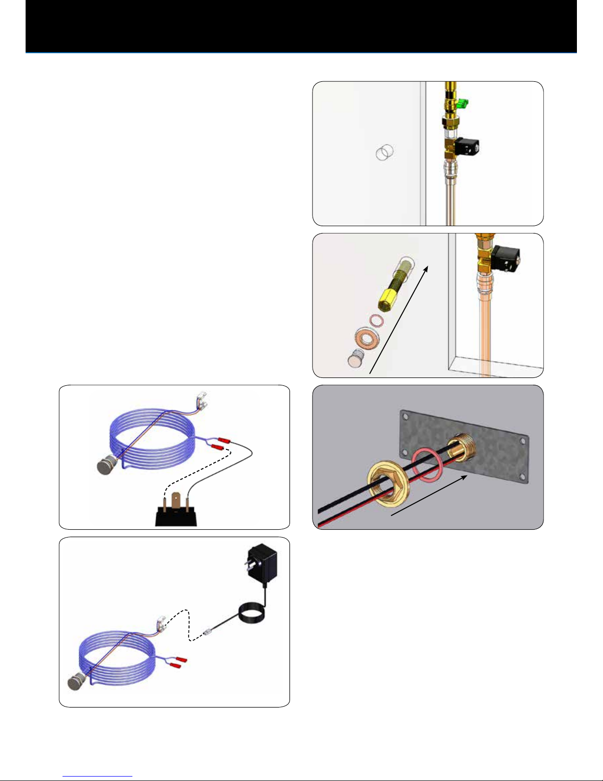
6. Connect the shut off valve and upper section of the union (as
shown) (FIGURE 1.2 and 1.3)
FIGURE 1.2 FIGURE 1.3
UPPER
SECTION OF
FLUSH VALVE
LOWER
SECTION OF
FLUSH VALVE
SPARGE
CONNECTION
(ADAPTOR OR AIR
GAP)
FIGURE 1.1
Ø30
INSTALLATION INSTRUCTIONS

4 Call 1300 369 273 www.enware.com.au
EMF305M
7. Connect lower half of flush valve to union and spreader pipe
(FIGURE 1.2 or 1.3 then 1.4)
Note: If using EMFS10-Air Gap also refer to FIGURE 1.9 on page 4
8. Fit the piezo, adaptor and tail through the cutout in the wall.
Note the tail can be cut and shortened if required. (FIGURE 1.5)
Note: a wall thickness of 55mm is required to fit the adaptor.
9. Fit mounting plate with locknut and red fibre washer on back of
wall (FIGURE 1.6)
Note: fixing screws of the clients choice can be used to secure
the backplate to the wall.
10. Plug piezo spade connectors onto solenoid (FIGURE 1.7)
11. Plug in transformer. Turn on to test the operation of the valve. If
the valve clicks and resets, it is working. (FIGURE 1.8)
FIGURE 1.4
FIGURE 1.6 (View from behind wall)
FIGURE 1.5
FIGURE 1.8
FIGURE 1.7
INSTALLATION INSTRUCTIONS

www.enware.com.au Call 1300 369 273 5
EMF305M
Flush Valve
Air Gap
SINGLE STALL
Flush Valve
Air Gap
600 MAX
TROUGH
1.9 INSTALLATION OF AIR GAP EMFS10
- Air gap must be installed vertically to prevent leakage
- Fit air gap to solenoid (use thread tape or similar to seal)
- Fit sparge 25mm pipe to air gap.
Solenoid
Air Gap
Sparge Pipe
Sparge Nut
O-Ring
INSTALLATION INSTRUCTIONS

6 Call 1300 369 273 www.enware.com.au
EMF305M
2.2 SPARE PARTS
2.1 EXPLODED VIEW
2.3 OPTIONAL PART
FIGURE 2.1
Piezo Mount
Adaptor
Solenoid
Piezo
Backplate
Filter
Union
Connection
Nipple
Transformer
Red Fibre
Washer
Tail
Shut off valve
Backnut
EMDS800 24V Transformer - 1.8M Lead
EMFS300 Switch Piezo 22MM S/S Urinal
EMS804 Solenoid 3/8” 24V AC
ENMS123 1/2” Strainer
EMFS304 Shut off valve
EMFS10 1/2” Air Gap
EMDS801 2m Power to piezo extension cable
PRODUCT COMPONENTS AND SPARE PARTS LIST

www.enware.com.au Call 1300 369 273 7
EMF305M
3.1 SERVICE INSTRUCTIONS
Refer to trouble shooting chart to help determine specific problems.
Spare part kits should be on hand before servicing this unit.
3.2 TROUBLE SHOOTING
Refer to the following trouble shooting chart for specific problems and solutions. Service instructions are supplied with spare part kits
FAULT / SYMPTOM CAUSE RECTIFICATION
Button pressed - water does not flow Loose connection on leads Reconnect electrical connections
Piezo switch is not working (no
light appears when unit switched
on)
Piezo switch or transformer faulty
Dirty Filter Turn off shut off valve. Open union and remove
lower section of valve. Clean or replace filter.
Supply pressure issue Ensure pressure delivered to unit is above
200kpa and below 500kPa (dynamic)
Water does not stop flowing Debris or scale in the solenoid Remove solenoid, pull out plunger and spring
& clean them. Use scale remover if required.
When replacing plunger, ensure spring is in
vertical position
Dirty Filter Turn off shut off valve. Open union and remove
lower section of valve. Clean or replace filter.
Supply pressure issue Ensure pressure delivered to unit is above
200kpa and below 500kPa (dynamic)
Flush pattern not fully covering bowl Supply pressure issue Ensure pressure delivered to unit is above
200kpa and below 500kPa (dynamic)
Supply pipe inadequate size Ensure supply is 20mm (minimum)
Too little water delivered Supply pressure issue Ensure pressure delivered to unit is above
200kpa and below 500kPa (dynamic)
Supply pipe inadequate size Ensure supply is 20mm (minimum)
Trying to flush too large an area Ensure no more than 450 wall space or 1 stall
is being serviced by valve (25mm supply if
covering 600mm of wall space)
3.3 FILTER CLEANING
This flush valve is provided with a stainless steel filter preventing
foreign particles from entering the lines. If the water flow has
decreased, this may be because the filter is clogged. They can be
cleaned as follows:
1. Turn-off the water shut off valve
2. Disconnect flush valve at union and separate from
spreader pipe
3. Remove the filter & wash it under running water. It may be
necessary to replace the filter (spare parts can be ordered
from Enware)
4. Reinsert the filter and refit the flush valve
6. Turn on the water shut off valve
7. Make sure that there is no water leakage
3. SERVICE AND MAINTENANCE

Table of contents
Other enware Bathroom Fixture manuals
Popular Bathroom Fixture manuals by other brands

Hans Grohe
Hans Grohe Raindance Lift 27008000 Instructions for use and assembly instructions

Spectrum Brands
Spectrum Brands Pfister Tisbury R89-XTB Maintenance & Care Guide

Kohler
Kohler Toobi K-T8975 Installation and care guide

Jacuzzi
Jacuzzi Glint 80x80 Preinstallation manual

Hans Grohe
Hans Grohe Push open 50100 Series Assembly instructions

Kebo
Kebo SH-PN-7058 quick start guide