www.enware.com.au Call 1300 369 273 19
SETTING OUTLET TEMPERATURE
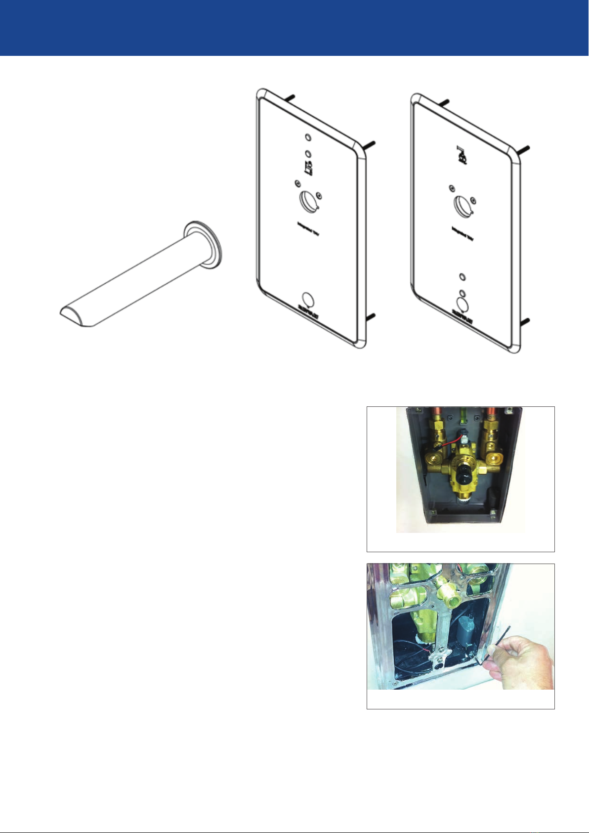
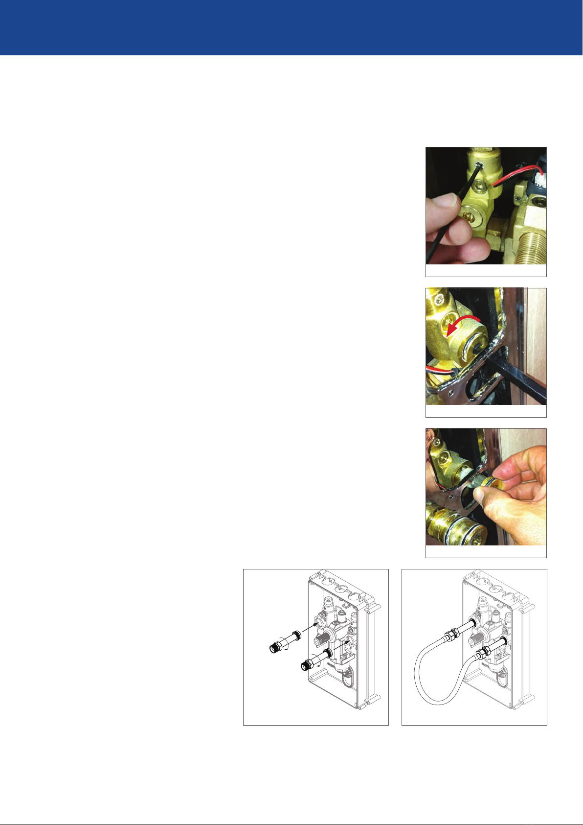
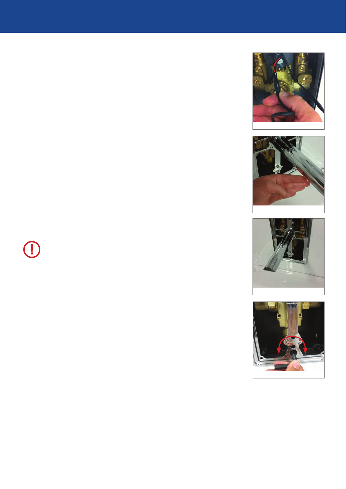
STEP 1 Turn on the integral isolation valves using a 2.5mm
Allen key or at head screw driver (if not already
turned on).
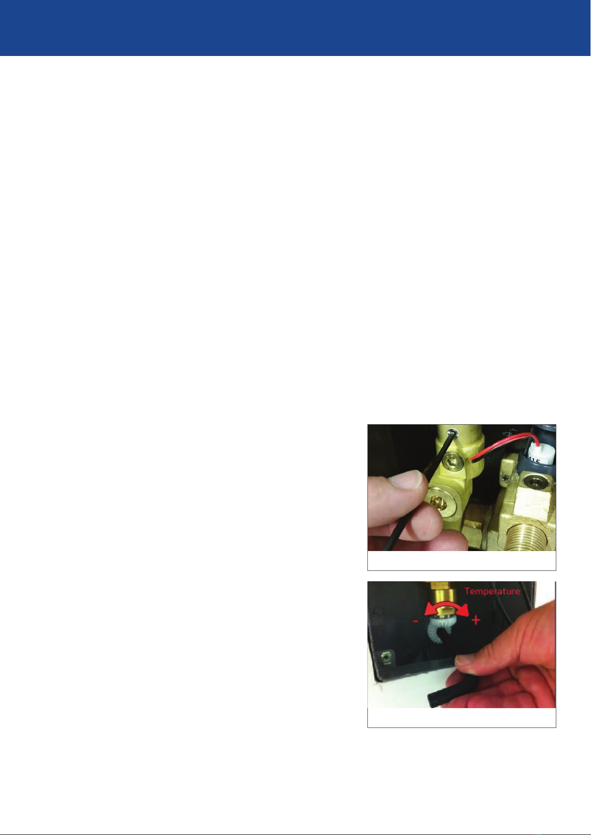
SEE IMAGE 26
STEP 2 Insert the 3/8” Allen key into the mixer’s
temperature adjustment gear.
STEP 3 If the thermostatic mixer is closed, turn the tap
on by rotating the Allen key clockwise. Check the
temperature of the water with a hand held digital
thermometer. With the thermometer held within the
ow stream, rotate the Allen key until the desired
(maximum) temperature is achieved.
SEE IMAGE 27
STEP 4 Once this desired temperature is set, make sure it
stays steady for a minimum of 60 seconds. Remove
the Allen key without changing the temperature
gear position.
Due to the installed water supply conditions being
different from those applied in the laboratory test,
it is appropriate at commissioning to carry out
simple checks and tests on each mixer to provide
a performance reference point for future scheduled
servicing.
In all cases the following must be checked to ensure
correct operational performance of the SQX™ valve:
• The intended installation matches the
performance brief of the SQX™ point of use
thermostatic.
• The supply temperatures and pressures are
within the permitted range as specied
in the Technical table - Installation Conditions
on Page 6.
Upon completion of the installation, the valve
should be tested and commissioned as per the
procedure outlined in this guide or as specied by
the local authority. The entire procedure should be
read through thoroughly prior to commissioning the
valve. A calibrated digital thermometer, having rapid
response time with maximum temperature hold
will be required to check and set the outlet mixed
temperature of the valve.
To test the temperature, allow the mixed heated
water to ow for at least 60 seconds - this allows
for a stable temperature reading. For optimum
performance, a ow rate of at least 4 Lpm is
recommended.
NOTE: The solenoid valve is a latching solenoid - it remains in either open or closed position
if power supply is not connected. Factory setting is at fully open position.
COMMISSIONING OF THE VALVE
IMAGE 26
IMAGE 27
COMMISSIONING