EOC NYX-14 User manual

Important Export Restrictions! Shipment and Refund The mer-
chandises which are in stock (we are not responsible for the prob-
lems caused by the delivery) will be sent to the customer within 5
days. If merchandise is not available at the moment of the order
placement, we will do our best to deliver it as soon as possible.
In case of unavailability an EOC employee informs the customer
and makes necessary arrangements for the prompt delivery of the
missing item to the stock. If it is not possible to fulll the order,
the customer is informed immediately and the paid money is re-
funded or a stock credit is advised. Please carefully inspect your
merchandise immediately upon receipt. If any item does not meet
your approval, you may return it to EOC GmbH during the follow-
ing 14 days for refund. Shipping, handling, and EOC charges are
non-refundable. Return shipping and insurance costs remain the
responsibility of the customer. All items returned for exchange or
refund must be unused, in the exact condition as the item was re-
ceived and must come with the manual and all included accesso-
ries. The 14-day period starts once the merchandise is received by
or on behalf of the customer from the shipping carrier and ends
up the day EOC receives the merchandise back to its facilities. If a
customer sends the item to the warranty service the customer has
to attach the copy of the payment receipt. If there is no payment
receipt, the customer will carry the repair costs. EOC does not ac-
cept any warranty responsibility for the devices that have been
opened, dissembled or modied in any way by the customer.
NYX-14
NYX-14M
Night Vision Monocular
OPERATION AND
MAINTENANCE MANUAL
EOC EUROPEAN OPTIC COMPANY

2
The information provided in this manual is for familiarization purposes only; the contents may undergo further
changes with no commitment by EOC Company to notify customers of any updates.
EOC Company assumes no responsibility for any misprints or other errors that this manual may contain.
©2012 by EOC Company. All rights reserved.
SAFETY SUMMARY
Before operating this product, carefully read and study this Operation and Maintenance Manual.
The NYX-14 is a precision electron-optical instrument, and requires careful handling. To avoid damage
to the equipment or physical harm to the user when operating the NYX-14, follow all WARNINGS, CAU-
TIONS and NOTES.
Below you will nd denitions of the following alerts that appear throughout this Manual:
WARNING — Identies a clear danger to the person operating the equipment.
CAUTION – Identies risk of damage to the equipment.
NOTE – Serves to highlight essential procedures, conditions, and statements, or convey important in-
structional data to the user.
WARNING:
This product contains natural rubber latex which may cause allergic reactions! The FDA
has reported an increase in the number of deaths that are associated with an apparent sensitiv-
ity to natural latex proteins. If you are allergic to latex, it is a good idea to learn which products
contain it and strictly avoid exposure to those products.
WARNINGS:
• Thelightfromtheunitinfrared(IR)illuminatorisinvisibletotheunaidedeyewhenusedin
total darkness. However, the light can be detected by other Night Vision Devices (NVD).
•ToreducetheriskofdetectionbyanotherNVD,avoidprolongedactivationoftheIRillumina-
tor.
•TheIRlightismoredetectablebyanNVDwhenusedinsmoke,fogandrain.Avoidprolonged
activation of the unit IR illuminator in these conditions.
• Theintensier’sphosphorscreencontainstoxicmaterials.Pleasenotethefollowing:
— If the intensier tube breaks, be extremely careful to avoid inhaling the phosphor screen
material. DO NOT allow the material to come in contact with your mouth, eyes, or any open
wounds on the skin.
— If the phosphor screen material comes in contact with your skin, wash it o immediately with
soap and water.
— If you inhale or swallow any phosphor screen material, drink a lot of water, induce vomiting,
and seek medical attention as soon as possible.

3
CAUTION:
• TheNYX-14isaprecisionelectron-opticalinstrument,andmustbehandledcarefullyatall
times to prevent damage to the device and danger to the user.
• Toprotecttheintensiertube,do not remove the lens cap of the NYX-14 when the monocu-
lar is being operated in daylight conditions, or when the device is not in use.
• UseoftheNYX-14inbrightlylitconditionsmaydamagetheunit’sintensiertube.
• Brightlightsourcessuchasrelight,headlights,searchlights,etc.candamagetheNYX-14.
Avoid exposing the unit to these types of light sources.
• Beforeremovingthelenscap,verifythatthephotoreceiverisopen.
• DONOTforgettoopenthephotoreceiveraftercompletingyourmission.
• DONOTattempttoforcethecontrolspasttheirstoppingpoints,asthismaycausedamage
to the mechanisms.
• Theunitmaybebadlydamagedifthetripodonwhichitismountedcollapsesoroverturns.
Remove the unit from the tripod if it is not within your reach.
• Beforereplacingtheintensiertube,conrmthatitisnolongercoveredbywarranty.
• ThoroughlydryeachcomponentoftheNYX-14beforeplacingtheminthestoragecase.
NOTES:
• Theequipmentrequiressomeambientlight(moonlight,starlight,etc.)tooperate.
• Performanceofthedeviceinnighttimeconditionsdependsonthelevelofambientlightin
the environment. Please remember the following:
— The level of ambient light is reduced by the presence of clouds, shade, or objects that block
natural light (trees, buildings, etc.).
— The equipment is less eective when operated in shadows and other darkened areas.
— The equipment is less eective when operated in rain, fog, sleet, snow, dust or smoke.
— The equipment will not “see” through dense smoke.
• Atoperatingtemperaturesbelow-20°C(-4°F),theuseofanalkalinebatteryis notrecom-
mended, as the battery life will be severely reduced. Under said conditions, lithium-iron disul-
de1.5VAAbatteriesortheirequivalentshouldbeused.
• TheIRilluminatorisintendedforincreasedillumination,asneeded,whenviewingataclose
distance of up to 3m.
• Forthepurposeofreturningdefectivecomponents,retainallpackagingmaterials.

4
LIST OF CONTENTS
TITLE PAGE
Safety Summary 2
List of Contents 4
List of Figures 5
List of Tables 6
How to Use This Manual 6
1. INTRODUCTION 7
1.1 General Information 7
1.1.1 Type of Manual 7
1.1.2 Model Number and Equipment Name 7
1.1.3 Purpose of Equipment 7
1.1.4 Reporting Equipment Improvement Recommendations 7
1.2 Warranty Information and Registration 8
1.2.1 Warranty Information 8
1.2.2 Limitation of Liability 8
1.2.3 Product Warranty Registration 8
1.2.4 Obtaining Warranty Service 9
1.3 Cross References 9
1.4 List of Abbreviations 10
2. DESCRIPTION AND DATA 11
2.1 System Description 11
2.2 Specications 12
2.3 Standard Components 14
2.4 Optional Equipment 15
2.5 Key Features 17
3. OPERATING INSTRUCTIONS 18
3.1. Installation and Mounting 18
3.1.1 Battery Installation 18
3.1.2 Mounting the NYX-14 to a Goggle Kit 19
3.1.3 Mounting the NYX-14 to a Helmet 19
3.1.4 Mounting the NYX-14 to a Dual Bridge 20
3.1.5 Mounting an IR Illuminator to the NYX-14 21
3.1.6 Mounting Accessory Lenses to the NYX-14 21
3.1.7 Mounting a Camera/Camcorder to the NYX-14 22
3.1.8 Universal Camera Adapter Application 21
3.1.9 Mounting a Demist Shield to the NYX-14 22
3.1.10 Mounting a Sacricial Window to the NYX-14 23
3.2 Controls and Indicators 23
3.2.1 Controls and Indicators 23
3.3 Operating Procedures 24
3.3.1 Operating Procedures 24
3.3.2 IR Illuminator Operations 25
3.3.3 Operating Under Changing Light Conditions 25
3.3.4 NYX-14 Shut-Down 26

5
3.4 Storage 26
3.4.1 Preparation for Storage 26
4. PREVENTIVE MAINTENANCE AND TROUBLESHOOTING 27
4.1 Preventive Maintenance Checks and Services 27
4.1.1 Preventive Maintenance Checks and Services (PMCS) 27
4.2 Troubleshooting 29
4.2.1 Operator Troubleshooting 29
4.3 Identication of Operational Defects 29
4.3.1 Operational Defects 29
4.3.2 Cosmetic Blemishes 30
4.4 Maintenance 32
4.4.1 General 32
4.4.2 Cleaning Procedures 32
4.4.3 Battery Removal and Replacement 32
4.4.4 Goggle Kit Maintenance 32
4.5 Service/Packing and Unpacking 33
4.5.1 Return Instructions 33
APPENDIX 35
A. NYX-14 List of Spare Parts 35
B. Intensier Tube Replacement Manual 36
C. Product Warranty Registration Card 38
Alphabetical Index 39
LIST OF FIGURES
FIGURE TITLE PAGE
2-1 NYX-14NightVisionMonocular 12
2-2 NYX-14 Standard Components 14
3-1 Battery Installation 18
3-2 Mounting the NYX-14 to a Goggle Kit 19
3-3 Mounting the NYX-14 to a Helmet 20
3-4 Mounting the NYX-14 to a Dual Bridge 20
3-5 Mounting an IR Illuminator to the NYX-14 21
3-6 Mounting Accessory Lenses to the NYX-14 21
3-7 Mounting a Camera/Camcorder to the NYX-14 22
3-8 Universal Camera Adapter Application 22
3-9 NYX-14 Controls 23
3-10 IR Illuminator Operations 25
3-11 Photoreceiver is Closed with Cap on the Pivot Plate 26
4-1 Shading 30
4-2 Edge Glow 30
4-3 Emission Points and Bright Spots 31
4-4 Fixed-Pattern Noise 31
4-5 Chicken Wire 31
4-6 Browpad Replacement 33

6
4-7 Chin Strap Reinstallation 33
4-8 Chin Cup Replacement 33
A-1 NYX-14 Spare Parts 35
B-1 Intensier Tube Replacement 37
LIST OF TABLES
TABLE TITLE PAGE
2-1 NYX-14 System Description 12
2-2 Mechanical Data 12
2-3 Electrical Data 13
2-4 Optical Data 13
2-5 Environmental Data 14
2-6 NYX-14 Standard Components 15
2-7 NYX-14 Optional Equipment 15
3-1 NYX-14 Controls and Indicators 24
4-1 Preventive Maintenance Checks and Services 27
4-2 Operator Troubleshooting 29
A-1 NYX-14 List of Spare Parts 35
HOW TO USE THIS MANUAL
USAGE
You must familiarize yourself with the entire manual before operating the equipment. Before perform-
ing any kind of maintenance on your device, read the section on maintenance in its entirety. Follow all
WARNINGS, CAUTIONS, and NOTES.
MANUAL OVERVIEW
ThismanualcontainssectionsonOperatingandMaintainingtheNYX-14NightVisionMonocular.
The list of Spare Parts can be found in Appendix A.
The Intensier Tube Replacement Manual can be found in Appendix B.
The Product Warranty Registration Card can be found in Appendix C.

7
1
INTRODUCTION
1.1 GENERAL INFORMATION
1.1.1 TYPE OF MANUAL
Operation and Maintenance (including a List of Spare Parts and an Intensier Tube Replacement Man-
ual).
1.1.2 MODEL NUMBER AND EQUIPMENT NAME
NYX-14 Multi-Use Minimonocular
NYX-14M Multi-Use Minimonocular
1.1.3 PURPOSE OF EQUIPMENT
To provide the operator with the ability to observe at night under moonlight and starlight con-
ditions.
The NYX-14 can be used as a handheld, head-mounted or helmet-mounted to allow walking, short-
range surveillance, map reading, vehicle maintenance, and administering of rst aid.
TheNYX-14allowsforhorizontalandverticaladjustmentswhenmountedtotheuser’sheadorhelmet,
and is equipped with an infrared light-emitting source (IR illuminator).
1.1.4 REPORTING EQUIPMENT IMPROVEMENT RECOMMENDATIONS
Recommendations from the user for improvements to the device are encouraged.
Mail your comments to EOC EUROPEAN OPTIC COMPANY GmbH, Dopplerweg 4A, 40591, Düsseldorf,
Germany.
Or, send an email to info@eoccompany.de.

8
1.2 WARRANTY INFORMATION AND REGISTRATION
1.2.1 WARRANTY INFORMATION
This product is guaranteed to be free from manufacturing defects in material and workmanship under
normal use for a period of two (2) years from the date of purchase. In the event that a defect covered by
the below warranty occurs during the applicable period stated above, EOC Company, at its discretion,
will either repair or replace the product; such action on the part of EOC Company shall be the full extent
ofEOCCompany’sliability,andtheCustomer’ssoleandexclusivereparation.Thiswarrantydoesnot
cover a product if it has (a) been used in ways other than its normal and customary manner; (b) sub-
jected to misuse; (c) subjected to alterations, modications or repairs by the Customer of by any party
other than EOC Company without prior written consent of EOC Company; (d) special order or “close-
out” merchandise or merchandise sold “as-is” by either EOC Company or the EOC Company dealer;
or (e) merchandise that has been discontinued by the manufacturer and either parts or replacement
units are not available due to reasons beyond the control of EOC Company. EOC Company shall not be
responsibleforanydefectsordamagethatinEOCCompany’sviewarearesultfromthemishandling,
abuse, misuse, improper storage or improper operation of the device, including use in conjunction with
equipment that is electrically or mechanically incompatible with, or of inferior quality to, the product,
as well as failure to maintain the environmental conditions specied by the manufacturer. CUSTOMER
IS HEREBY NOTIFIED THAT OPERATION OF THE EQUIPMENT DURING DAYLIGHT HOURS OR UNDER ANY
EXCESSIVE LIGHT CONDITIONS MAY PERMANENTLY DAMAGE THE INTERNAL COMPONENTS OF THE
UNITANDSAIDDAMAGEWILLNOTBECOVEREDUNDERTHISWARRANTY.Thiswarrantyisextended
only to the original purchaser. Any breach of this warranty shall be enforced unless the customer noti-
es EOC Company at the address noted below within the applicable warranty period.
The customer understands and agrees that except for the foregoing warranty, no other warranties
written or oral, statutory, expressed or implied, including any implied warranty of merchantability or
tness for a particular purpose, shall apply to the product. All such implied warranties are hereby and
expressly disclaimed.
1.2.2 LIMITATION OF LIABILITY
EOC Company will not be liable for any claims, actions, suits, proceedings, costs, expenses, damages or
liabilities arising out of the use of this product. Operation and use of the product are the sole respon-
sibility of the Customer. EOC Company’s sole undertaking is limited to providing the products and
services outlined herein in accordance with the terms and conditions of this Agreement. The provision
of products sold and services performed by EOC Company to the Customer shall not be interpreted,
construed, or regarded, either expressly or implied, as being for the benet of or creating any obliga-
tiontowardanythirdpartyoflegalentityoutsideEOCCompanyandtheCustomer;EOCCompany’s
obligationsunderthisAgreementextendsolelytotheCustomer.EOCCompany’sliabilityhereunder
for damages, regardless of the form or action, shall not exceed the fees or other charges paid to EOC
Companybythe customer or customer’sdealer.EOC Company shallnot,in any event, beliable for
special, indirect, incidental, or consequential damages, including, but not limited to, lost income, lost
revenue, or lost prot, whether such damages were foreseeable or not at the time of purchase, and
whether or not such damages arise out of a breach of warranty, a breach of agreement, negligence,
strict liability or any other theory of liability.
1.2.3 PRODUCT WARRANTY REGISTRATION
In order to validate the warranty on your product, EOC Company must receive a completed Product
Warranty Registration Card for each unit, or the Customer can complete a warranty registration on our
website, at www.eoccompany.de. Please complete the included form (Appendix C) and immediately
mail it to our Service Center:
EOC EUROPEAN OPTIC COMPANY GmbH
Dopplerweg 4A,
40591, Düsseldorf, Germany.

9
1.2.4 OBTAINING WARRANTY SERVICE
To obtain warranty service on your unit, the End-user (Customer) must notify the EOC Company service
department via email. Send any requests to info@eoccompany.de to receive a Return Merchandise
Authorization number (RMA). When returning any device, please take in the product to your retailer,
or send the product, postage paid and with a copy of your sales receipt, to EOC Company service cen-
ter at the address listed above. All merchandise must be fully insured with the correct postage; EOC
Company will not be responsible for improper postage or merchandise that becomes lost or damaged
during shipment. When sending product back, please clearly write the RMA# on the outside of the
shippingbox.PleaseincludealetterthatindicatesyourRMA#,theCustomer’sName,aReturnAddress,
reason for the return, Contact information (valid telephone numbers and/or an e-mail address), and
proof of purchase that will help us to establish the valid start date of the warranty. Product merchan-
dise returns that do not have an RMA# listed may be refused, or a signicant delay in processing may
occur. Estimated Warranty service time is 10-20 business days. The End-user/ Customer is responsible
for postage to EOC Company for warranty service. EOC Company will cover return postage/ shipping
after warranty repair to the End-user/ Customer only if the product is covered by the aforementioned
warranty. EOC Company will return the product after warranty service by domestic UPS Ground service
and/ or domestic mail. Should any other requested, required or international shipping methods be
necessary, the postage/ shipping fee will be the responsibility of the End-user/ Customer.
1.3 CROSS REFERENCES
COMMON NAME OFFICIAL NAME
Allen Wrench Socket Head Screw Key
Battery Compartment Battery Box Cover
Shipping Case Textile Bag
Cotton Swab Disposable Applicator
Neoprene Jack Plug Plug Assembly
O-Ring Gasket
Safety Screw Electrical Dial-Knob Lock
Pattern Generator Optical Instrument Reticle
Lens Covers Exit Port Covers
Paddle Switch Remote Cable Switch
Batteries AA
Technical Manual Operator and Field Maintenance Manual
Tape Fastener Loop Fastener, Loop Tape
Tape Fastener Hook Fastener, Hook Tape

10
1.4 LIST OF ABBREVIATIONS
C Celsius (Centigrade)
CCW counterclockwise
Cont’d Continued
CW clockwise
Dia diameter
F Fahrenheit
FOV FieldofView
g gram
Gen Generation
H Height
hr hour
IR infrared
IT Intensier Tube
L Length
LED Light Emitting Diode
lx lux
m meter
mA milliampere
min minute
mm millimeter
mW milliwatt
nm nanometer
No Number
NV NightVision
NVD NightVisionDevice
Para Paragraph
PMCS Preventive Maintenance Checks and Services
QTY Quantity
RMA# Return Merchandise Authorization number
s second
seq sequence
SR Service Representative
VDC VoltsDirectCurrent
V Volt
W Width

11
2
DESCRIPTION AND DATA
2.1 SYSTEM DESCRIPTION
The NYX-14 is a hand-held, head-mounted or helmet-mounted night vision system that allows the user
to operate it while walking, conducting short-range surveillance, reading maps, conducting vehicle
maintenance, or administering rst aid in both moonlight and starlight conditions.
The NYX-14 utilizes the principle of intensication of the residual light that is reected from the sur-
rounding objects. The optical system of the unit consists of an objective lens, an intensier tube (IT),
and an eyepiece.
The NYX-14 automatic brightness adjustment system retains the same gain (image brightness), even
under unsteady light conditions.
The NYX-14 automatic protective system controls illumination through a photoreceiver. If the illumina-
tion level surpasses 100-300 lx for more than 10 s, the unit will shut o automatically.
A built-in IR illuminator makes it possible to use the unit in low light or total darkness.
The NYX-14 uses LED lights to indicate illumination level, low battery, and to show the user that the IR
illuminator is on.
TheNYX-14allowsforverticalandfore-and-aftadjustmentwhenmountedtotheuser’sheadorhel-
met, when focusing the lens, and when focusing the eyepiece.
Additionally, the NYX-14M version incorporates gain control, which allows the user to increase or de-
crease the brightness of the image to compensate for overly bright or extremely dark conditions.
NOTE:
The equipment requires some light (moonlight, starlight, etc.) to operate. Performance of the
device depends upon the level of ambient light in the environment. Please remember the fol-
lowing:
— The level of ambient light in the environment is reduced by the presence of clouds, shade,
or objects that block natural light (trees, buildings, etc.
— The equipment is less eective when operated in shadows and other darkened areas.
— The equipment is less eective when operated in rain, fog, sleet, snow, or smoke.
— Under starlight conditions, particularly in low-contrast environments such as snow-cov-
ered territory, sandy deserts, large bodies of water or grassy hills, the visibility may degrade,
thereby disguising or masking changes in terrain.
— The equipment will not “see” through dense smoke.

12
13
9
7
10
FIGURE 21. NYX14 NIGHT VISION MONOCULAR
4
12
5
6
2
11
3
1
8
14
15
TABLE 21. NYX14 SYSTEM DESCRIPTION
ITEM DESCRIPTION ITEM DESCRIPTION
1Body 9 Photo Receiver
2Rail 10 Pivotal Focusing Lens
3 Eyepiece Ring 11 IR Illuminator
4Eyepiece 12 Turn-pull Function Switch
5Eye-cup 13 Focus Ring
6 Battery Cap 14 Lens
7 Gain Control Knob * 15 Lens Cap
8 Battery Compartment
*For NYX-14 M version.
2.2 SPECIFICATIONS
TABLE 22. MECHANICAL DATA
EQUIPMENT ITEM DIMENSIONS, MM L X W X H/DIA X L WEIGHT, G
NYX-14/NYX-14MNightVisionMonocular 140х49х69 398 /408**
Flip-up Helmet Mount* 120х170х150 280
Goggle Kit* 280х180х80 295
Dual Bridge* 54x22x24 34
Sacricial Window* Dia 30х7 5
Demist Shield* Dia 8.5х5.5 4

13
EQUIPMENT ITEM DIMENSIONS, MM L X W X H/DIA X L WEIGHT, G
Camera Adapter* Dia 60х22 52
3X Afocal Lens* Dia 77х95 553
3X Lens* Dia 60х109 450
5X Lens* Dia 80х141 500
8X Lens* Dia 96х211 730
8X Lens Dia 96х211 730
* Optional
** For NYX-14 M version.
TABLE 23. ELECTRICAL DATA
ITEM DATA
Battery OneAA(1.5V)or123A(3V)
Consumption Current*:
-at1.5VDC
-at3.0VDC
75 mA
38 mA
Continuous Operation* at 20 oC (68oF):
- AA Alkaline Battery
- 123A Lithium Battery
30 (IT Gen. 2+) / 25 (IT Gen. 3)
60 (IT Gen. 2+) / 50 (IT Gen. 3)
*With IR illuminator o.
TABLE 24. OPTICAL DATA
ITEM DATA
Magnication:
— with 1X Lens
— with 3X Lens*
— with 5X Lens*
— with 8X Lens*
— with 3X Afocal Lens* and F27 Lens
(1±0.05) X
(3.3±0.2) X
(5±0.2) X
(8±0.5) X
(3±0.15) X
1X Lens:
— Focal Length
— Lens F/number
27 mm
1:1.2
Focus Range:
— with 1X Lens
— with 3X Lens*
— with 5X Lens*
— with 8X Lens*
— with 3X Afocal Lens*
0.25 m to innity
5 m to innity
10 m to innity
15 m to innity
5 m to innity
FOV:
— with 1X Lens
— with 3X Lens*
— with 5X Lens*
— with 8X Lens*
— with 3X Afocal Lens*
40°
12°30’
9°30’
6°30’
9°
TABLE 22. CONTINUED

14
ITEM DATA
Exit Pupil Diameter 14 mm
Eyepiece Focal Length 27 mm
Eye Relief 25 mm
Eyepiece Diopter Adjustment -6 to +2 diopters
Built-in IR Illuminator
— Power
— Illumination Range
— Focus Distance
— Illumination Wavelength
50 mW
20 m
3 m
850 nm
* Optional.
TABLE 25. ENVIRONMENTAL DATA
ITEM DATA
Operating Temperature -40to+50°C
Storage Temperature -50to+70°C
Humidity 95%,25°Cto40°Cfor48hr
Illumination Required Natural night illumination
(overcast starlight to moonlight)
Immersion 20 m for 1 hr
MIL-STD -810 Complies
2.3 STANDARD COMPONENTS
The standard components of the NYX-14 are shown in Figure 2-2 and listed in Table 2-6.
The ITEM NO. column indicates the number used to identify items in Figure 2-2.
1
2
3
4
567
FIGURE 22. NYX14 STANDARD COMPONENTS
TABLE 24. CONTINUED

15
TABLE 26. NYX14 STANDARD COMPONENTS
ITEM NO. DESCRIPTION QUANTITY
1NightVisionMonocular 1
2 Lens Cap 1
3Eye-cup 1
4 Battery Adapter 1
5 Battery 123A Lithium 1
6 Operation and Maintenance Manual 1
7 Carrying Case 1
1) NYX-14 Night Vision Monocular
Monocular night vision device with unity magnication.
2) Lens Cap
A cap used to protect the lens and to be used when testing the unit in daylight.
3) Eye-cup
A rubber cup used to protect the eyepiece as well as provide comfort for the operator.
4) Battery Adapter
Allowsofuseofasingle3VCR123or1.5VAAbatteries.
5) Battery 123A Lithium
A single, 123A lithium battery used to power the unit.
6) Operation and Maintenance Manual
Provides safety information, equipment description, mounting procedures, operating instructions,
and preventive maintenance checks and service (including a List of Spare Parts and an Intensier Tube
Replacement Manual).
7) Carrying Case
A protective case used for storing and carrying of the NYX-14 and its accessories.
2.4 OPTIONAL EQUIPMENT
Optional items are shown and listed in Table 2-7.
The PART NO. column indicates the primary number used by the manufacturer to identify an item.
TABLE 27. NYX14 OPTIONAL EQUIPMENT
IMAGE DESCRIPTION PART NO.
3X Afocal Lens
Quickly converts the NYX-14 into a long-range night
vision device. Ideal for long range observation.
ANAF3X0002
3X Lens
Quickly converts the NYX-14 into a long-range night
vision device. Ideal for long range observation.
ANLE3X00004

16
IMAGE DESCRIPTION PART NO.
5X Lens
Quickly converts the NYX-14 into a long-range night
vision device. Ideal for long range observation.
ANLE5X0002
8X Lens
Quickly converts the NYX-14 into a long-range night
vision device. Ideal for long range observation.
ANLE8X0002
Goggle Kit
Adjustable universal assembly that secures the
NYX-14totheoperator’sheadprovidinghands-free
operation.
ANHG000004
Flip-up Helmet Mount
Helps to mount the NYX-14 on a range of ballistic
helmets.
ANHM000008
Shutter Eye Guard
Prevents light from being emitted by the NYX-14
eyepiece.Iftheuser’sfaceisilluminated,theybe-
come visible to others in the eld, and their position
becomes compromised.
ANEC000001
IR810 IR Illuminator
Extra long-range infrared illuminator. Provides
greater viewing capabilities when the environment
has little or no ambient light.
IAIR810IR000001
IR850 IR Illuminator
Extra long-range infrared illuminator. Provides
greater viewing capabilities when the environment
has little or no ambient light.
IAIR850IR000001
Dual Bridge
An adapter that allows the NYX-14 to be attached in
a binocular conguration to a goggle kit or ip-up
helmet mount.
ANKI000003
Camera Adapter
An adapter with step down ring that allows the NYX-
14 to be attached to any 35 mm SLR camera or 8 mm
camcorder.
ANAM000016
Universal Camera Adapter
The system life tracker allows the user to verify opera-
tional start and end times of the individual unit, down
to the exact minute.
ANAM000006
TABLE 27. CONTINUED

17
IMAGE DESCRIPTION PART NO.
Life Tracker System
System/IIT service life recorder is a feature that lets
you measure the hours of operation (within one
minute) that have been used on the system.
ANCA000001
Demist Shield
When attached to the NYX-14 eyepiece, the demist
shield prevents condensation from developing on
the optics under rapid temperature changes.
ANLC000001
Sacricial Window
This feature is useful in environments with large
amounts of dust, dirt or debris in the air, as can be
found in environments with high-speed winds or
storm conditions. The sacricial window preserves
the objective lens of the NYX-14.
ANLC000002
Hard Shipping/Storage Case
A protective case used for the shipping/ storage of
the NYX-14 and its accessories.
ANHC000001
2.5 KEY FEATURES
Gen 2+/3 intensier tube
–
Automatic bright light cut-o system to protect the intensier tube
–
LED lights visible in the eyepiece viewing area that indicate operation of the bright light cut-
–
o system and IR illuminator, as well as to alert the user of a low battery
Built-in IR illuminator with pivotal lens to select between IR spot and ood beam
–
Left or right eye use
–
Lightweight
–
Compact and robust design
–
Easy to operate
–
Serviceability under severe conditions
–
High-performance
–
Highly reliable
–
Powered by single CR123A or AA battery
–
Head or helmet-mountable for hands-free usage
–
Adaptable for use with cameras
–
Automatic ON/ OFF feature with ip-up head/ helmet mount
–
Manual gain control (NYX-14M version) for the best possible image contrast under very high
–
and very low light conditions
Waterproof
–
Limited two-year warranty
–
TABLE 27. CONTINUED

18
3
OPERATING INSTRUCTIONS
3.1 INSTALLATION AND MOUNTING
CAUTION:
To protect the intensier tube when the sight is not in use or when it is being operated in day-
light, keep the protective lens cap securely tted over the lens.
3.1.1 BATTERY INSTALLATION
The NYX-14 operates on a single CR123A or AA battery.
Depending on the size of the battery used, it may be necessary to reposition the battery adapter
within the battery cap.
NOTE:
Ifoperatingthedeviceattemperaturesbelow-20°C(-4°F),theuseofanalkalinebatteryisnot
recommended, as the severe cold will adversely aect the life of the battery. In these conditions,
itisrecommendedthatyouusealithium-irondisulde1.5VAAbattery,oritsequivalent.
Install the CR123A battery as follows:
1. Unscrew the battery cap (A) and insert the CR123A battery (B), observing the polarity markings on
the body of the device.
2. With the battery adapter (C) installed, screw the battery cap (A) back on securely.
A
D
B
C
FIGURE 31. BATTERY INSTALLATION
B
A
C
Install the AA battery as follows:
1. Unscrew the battery cap (A).
2. Unscrew the battery adapter (C) from the cap, turn it around, and screw in the other end.
3. Insert the AA battery (D), observing the polarity markings as indicated on the body of the device.
4. Screw the battery cap (A) back into place.

19
3.1.2 MOUNTING THE NYX14 TO A GOGGLE KIT
Mount the NYX-14 to the optional goggle kit as follows:
1. Put on the goggle kit. Adjust the goggle kit strap pads until the goggles t securely around your
head. Remove the goggle kit.
2. Loosen the screw (A). While pushing down on the button (B), insert the NYX-14 rail into the guide (C)
of the goggle kit bracket. Tighten the screw (A). See Figure 3-2; the unit is shown in the correct position-
ing for the right eye.
3. Put on the goggle kit, now mounted with the NYX-14.
4. To adjust the equipment for greater comfort, loosen the screw (A) and move the unit along the guide (C).
5. The goggle kit has a ip-up mechanism. Push the button (D) of the goggle kit bracket and lift the unit
up until it reaches its top position. The unit will automatically turn o when it reaches this position.
6. Push the same button (D) to lower the unit into the correct viewing position. Turn the unit back on
to continue your session.
Figure 3-2 shows the NYX-14 in the correct position for the right eye. To readjust the unit for the other
eye, remove the unit from the goggle kit bracket. Turn the unit around (180º) and mount it on the
bracket through the rail on the second side. With the button (E) pushed, move the unit along the slide-
rail (F) until the desired, most comfortable position is reached.
To remove the NYX-14 from the goggle kit, loosen the screw (A), push the button (B), and slide the unit
out of the bracket guide (C).
C
D
E
F
B
A
FIGURE 32. MOUNTING NYX14 TO A GOGGLE KIT
3.1.3 MOUNTING THE NYX14 TO A HELMET
An optional ip-up helmet mount can be used to attach the NYX-14 to a helmet. The helmet mount ts
the NYX-14 securely onto helmet via a rugged strapping device and grooved hooks. With the helmet
mount,theNYX-14canbepositioneddirectlyinfrontoftheuser’seyes,orippedbackwards,outof
the eld of view.
Mount the NYX-14 to a helmet as follows:
1. Attach the mount to the helmet as shown in Figure 3-3.
2. Adjust and tighten the straps (A).
3. Loosen the screw (B). With the button (C) pushed down, insert the NYX-14 rail into the guide (D) of the
helmet mount bracket. Tighten the screw (B).
4. Put on the helmet with the NYX-14 attached.
5. Push the button (F) and move the unit along the slide-rail (G) until the most comfortable position is
reached.
5. To adjust the unit for comfort, loosen the screw (B) and move the unit along the guide (D).

20
7. To remove the NYX-14 and turn it around, push the button down (E) and lift the unit up until it reaches
the top position. Once it reaches this position, the unit will turn o automatically.
8. Push the same button (E) to lower the NYX-14 into the proper viewing position. Turn the unit on to
proceed with your mission.
In Figure 3-3, the NYX-14 is shown in the correct position for the right eye. To readjust the NYX-14 for
the left eye, reverse its positioning and reinstall it on the helmet mount bracket (see Figure 3-3). Use the
second unit rail located on the opposite side of the unit. Push the button (F) and move the unit along
the slide-rail (G) until the most comfortable position is reached.
To remove the NYX-14 from the helmet mount, loosen the screw (B), push down on the button (C), and
slide the unit out of the guide (D).
C
D
E
G
B
A
FIGURE 33. MOUNTING THE NYX14 TO A HELMET
F
A
3.1.4 MOUNTING THE NYX14 TO A DUAL BRIDGE
To install two NYX-14 units onto a single binocular device, use the optional dual bridge. Perform the
following steps:
1. Align the NYX-14 with the dual bridge (A).
2. Press down on the clamps (B) that are located on the front of the bridge.
3. Pull the unit back until the alignment boss is lined up against the groove (C) of the dual bridge. Push
the unit back until it is securely xed to the dual bridge.
4. Perform steps 1-3 with the second NYX-14 unit.
To remove the NYX-14 from the dual bridge, press down on the front clamps and slide the unit for-
ward.
To congure the NYX-14 for long-range observation with binoculars, mount the 3x accessory lenses to
the units as seen in Part 3.1.6 of this Manual.
To mount the dual bridge to the optional goggle kit, see Part 3.1.2 of this Manual.
C
B
A
FIGURE 3-4. MOUNTING THE NYX-14 TO A DUAL BRIDGE
This manual suits for next models
1
Table of contents
Other EOC Monocular manuals
Popular Monocular manuals by other brands
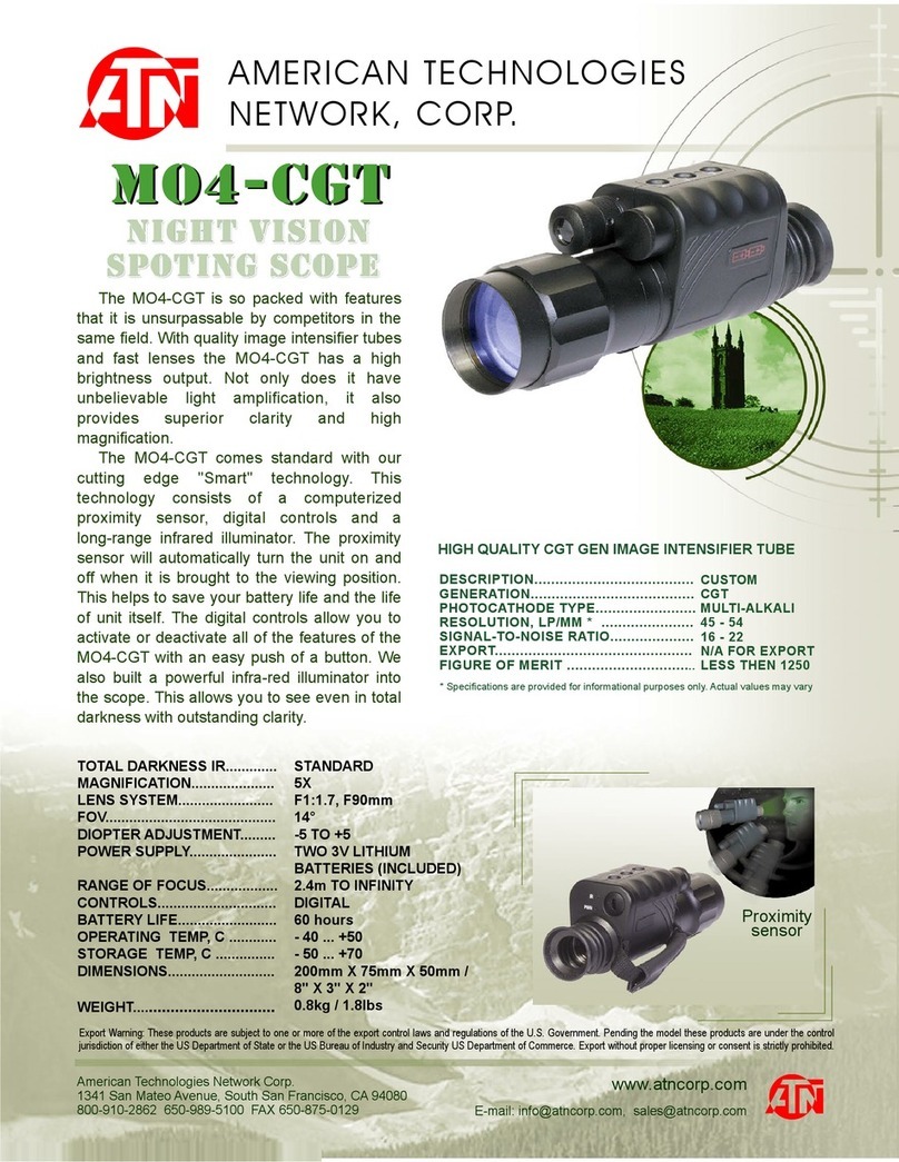
ATN
ATN MO4-CGT Specifications
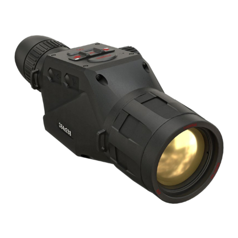
American Technologies Network
American Technologies Network ATN OTS 4T Series manual
Walther
Walther DigiViewPro operating instructions
ATN
ATN MO-4 user guide
L3 Communications
L3 Communications Thermal-Eye X200xp user manual

Bushnell
Bushnell Night Vision 26-0100 instruction manual


