EPC PLT300 Series User manual

PLT300
SERIES
DSP Controlled
UPS
100-120-160
kVA
3 Phase In - 3 Phase Out
USER MANUAL


CONTENTS
I. GENERAL DESCRIPTION......................................................................................3
1.1 Introduction.......................................................................................................3
1.2 Design Concept.................................................................................................5
1.2.1 Description of Blocks................................................................................6
1.2.2 Operating conditions of ups…………………………………………………..6
1.3 Front view of UPS Connection Panel ................................................................7
1.4 Technical Specifications....................................................................................8
II. UPS INSTALLATION ..............................................................................................9
2.1. Introduction.......................................................................................................9
2.2. Unpacking.........................................................................................................9
2.3. Equipment Positioning.......................................................................................9
2.4. Connecting the UPS Power Cables...................................................................10
2.5. Safety Earth......................................................................................................10
2.6. Cable Connection Procedure............................................................................10
2.6.1. UPS Power Cable Connection Terminals .................................................11
2.7. Battery Installation.............................................................................................12
III. FRONT PANEL .......................................................................................................14
3.1. Introduction.......................................................................................................14
3.2. Front Panel Menu Descriptions.........................................................................14
3.2.1 MEASUREMENTS menu ...........................................................................17
3.2.2 ALARM LOGS menu..................................................................................20
3.2.3 INFORMATION menu ................................................................................20
3.2.4 OPTIONS menu.........................................................................................21
3.2.5 COMMAND menu ......................................................................................24
3.2.6 TIME menu.................................................................................................24
3.2.7 SERVICE menu..........................................................................................25
3.2.8 ADJUST menu ...........................................................................................25
3.2.9 User Pasword.............................................................................................26
3.3. Alarms and warning messages .........................................................................26
3.4. Status Codes ....................................................................................................29
3.5. Alarm messages and quick troubleshooting......................................................35

1
IV. OPERATING INSTRUCTIONS................................................................................40
4.1 Introduction..........................................................................................................40
4.2 Operating ups in online mode ..............................................................................40
4.2.1 Starting ups from a completely shut down position......................................40
4.2.2 Shutting down the ups ................................................................................40
4.2.3 Switching the UPS from a normal
operation to maintenance bypass condition ..............................................41
4.2.4 Switching the UPS from a maintenance
bypass condition to normal operation........................................................41
4.3 UPS Behavior During mains outage ..................................................................42
V. MAINTENANCE .......................................................................................................43
5.1 Scheduled maintenance....................................................................................43
5.2 Daily checks......................................................................................................43
5.3 Weekly checks...................................................................................................43
5.4 Annual Maintenance..........................................................................................44
5.5 Storage conditions and transportation of ups.....................................................44
VI. FAULTS AND TROUBLESHOOTING....................................................................45
6.1. General Procedure for fault checking and troubleshooting.................................45
6.2. Before calling service.........................................................................................45
VII. UPS REMOTE MANITORING AND CONTROL.....................................................46
7.1. Using Serial Port................................................................................................46
7.2. Serial Communication port connection cable.....................................................46
7.3. Modem connection ............................................................................................47
7.3.1 Hardware configuration...............................................................................47
7.3.2 Functioning Principle...................................................................................47
7.3.3 Modem Programming Procedure ................................................................47
7.3.3.1 Smart modem (SM) programming...................................................47
7.3.4 Modem –UPS Connection Cable................................................................48
7.4. Dry contact (ınterface) connections ...................................................................48
7.5. Remote monitoring panel connection of UPS.....................................................48
VIII. EFFICIENT USAGE OF UPS IN TERMS OF ENERGY CONSUMPTION..............49

2
SAFETY
IMPORTANT
NOTICES
1. Read instructions carefully before installing and starting the UPS.
2. All warnings in the manual should be adhered to.
3. All operating instructions should be followed.
4. The unit should be supplied by a grounded outlet. Do not operate the unit without a ground source.
5. Power cables of the UPS should be routed carefully so that they are not to be walked on.
6. Please save this manual.
7. Please save or recycle the packaging materials.
WARNING!
Do not insert any object into ventilation holes or other openings.
To reduce the risk of fire or electric shock, install in temperature and humidity controlled
indoor area free of conductive contaminants.
To reduce the risk of fire, replace fuses with the same type and rating when necessary.
CAUTION!
Only qualified personnel should install or service UPS/batteries.
Risk of electric shock, do not remove cover. No user serviceable parts inside, refer
servicing to qualified service personnel.
The output may be energized even when the unit is not connected to a mains supply.
Risk of electric shock! Hazardous live parts inside. This unit is energized from the
battery supply even when the input AC power is disconnected.
To reduce the risk of electric shock, disconnect the UPS from the mains supply before
installing a computer interface signal cable. Reconnect the power cables only after signaling
interconnections have been made.
CAUTION
!
Units are designed to operate on the concrete
floor.
ABOUT THE
BATTERIES
CAUTION: RISK OF ELECTRIC SHOCK!
The battery circuit is not isolated from the mains voltage. Hazardous voltages
may occur between the battery terminals and the ground!
A battery can present a risk of electric shock or burn from high short circuit currents. The
following precautions should be taken when working on batteries :
* Remove watches, rings or other metal objects.
* Use tools with insulated handles.
The batteries in this UPS are recyclable. Batteries must be disposed of according to local
environmental laws. The batteries contain lead and pose a hazard to the environment and human
health if not disposed of properly.
Do not dispose of batteries in a fire. The batteries may explode. Do not open or mutilate the
batteries. They contain an electrolyte which is toxic and harmful to the skin and eyes. If electrolyte
comes into contact with the skin the affected area should be washed immediately.
The internal energy source (the battery) cannot be de-energized by the user.
When changing batteries, install the same number and same type of batteries.

3
I. GENERAL
DESCRIPTION
1.1 Introduction
EPC PLT300 Series Uninterruptible Power Supplies are double-conversion; on-line
UPS’s manufactured with the latest IGBT and PWM technology, to produce an
uninterruptible, fully DSP (Digital Signal Processor) controlled pure sine wave output to
critical loads.
EPC PLT300 Series units are 3-phase in/3-phase out devices, and they are
installed between a three phase critical load, and a 3-phase+N mains supply
The advantages of using PLT300 UPS:
Power blackout protection:
If the mains power fails, the UPS continues to supply the critical load using the energy
stored in its batteries, keeping the load immune from power disturbances.
Increased power quality:
The UPS has its own internal voltage and frequency regulating software, which
ensures that, its output to the critical load is maintained within close tolerances, independent of
voltage and frequency variations on the mains power lines.
Fully digital control by three DSP controller for each UPS:
The UPS is controlled by 3 independent DSP chips which are communicating each
other continuously. Rectifier, Inverter and User Interface modules have separate DSP’s to
achieve the highest performance. Each DSP module has many parameters to control and
monitor the system to have the best electrical power output and to help diagnostic.
Increased noise rejection:
By rectifying the input AC power to DC power and then converting it back to AC
(Double-Conversion) any electrical noise present on the input mains supply line is effectively
isolated from the UPS output. Therefore the critical load is supplied with only clean and
uninterrupted AC power.

4
Basic Features:
PWM and IGBT technology
Pure sinusoidal output wave form and true on-line topology
High input power factor (IGBT rectifier), Input current limiting
Low input current THD (IGBT rectifier)
Low output voltage THD
High AC/AC and DC/AC efficiency(up to 94%)
3 separate DSP (Digital Signal Processor) control
Cold-start feature
Static By-Pass feature: Provides uninterruptable transfer to bypass source in case of
overload or UPS fault.
Bypass leakage current sense system
Maintenance bypass switch and warning system, by-pass short circuit protection
Separate bypass input facility (split bypass), generator operation sense input
LCD alphanumeric display panel providing battery, load, voltage, power and status
information in detail to user
Improved diagnostics and correct fault infor mation
Up to 192 event memoryrecord system (7000 alarms or warnings total)
Real time clock and calendar system
Overload operation 10 minutes at 100% - 125% load, 1 minute at 125% - 150% load
Output overload, over-current and short circuit protection, output current limiting
Reliable operation at even 100% unbalanced load condition
Non-linear load supply feature (CF 3:1)
Double polarity battery (with common terminal)
Automatic and manual battery test and battery temperature compensation features
3 separate maintenance clock counters
Battery charge with current limiting
Automatic and manual boost charge feature
Battery deep discharge protection
Temperature protection with 3 separate sensors
Interactive communication
Diagnostic and settings with PC ability
2 separate RS232 communication ports (standard)
Multi UPS monitoring on same communication line by RS485 (optional)
4 dry contact alarm relay outputs as standard (8 optional relay outputs)
Improved remote monitoring panel system (optional)
RS232 port multiplexer (optional)
Direct network connection with optional SNMP support
MODBUS Adapter (optional)
AT command set definitions for dump modems
Communication via Windows based T-MON software and remote monitoring and control of
UPS via modem
Optional softwares compatible for most computer platforms
Abilityfor labeling of UPSs by users
Emergencypower-off support
Conformityto international and local standards
AC input and output filters
Optional graphic front panel
CE compliance
Input, bypass and load phase order protection
Optional leakage current alarm system
Input and output isolation transformers (optional)
Enhanced accessoryoptions
100.000 hours MTBF
2 years system warranty
10 years spare parts warranty

5
S3
Maintenance
Bypass
Switch
S2 SB
(F4-F5-F6)
Static
Bypass
-
S1 K1 - K2
S4
(F1-F2-F3) (F7-F8-F9)
Rectifier / Inverter
Charger
S5
(F10-F11-F12)
Battery
(Dual
Polarity)
1.2 Design Concept
3 PHASE
MAINS I/P
3 PHASE
AC Output
S1 (F1-F2-F3) : Rectifier Input Switch / Fuse
S2 (F4-F5-F6) : Bypass Input Switch / Fuse
S3 : Maintenance Bypass Switch
S4 (F7-F8-F9) : Output Switch / Fuse
S5 (F10-F11-F12) : Battery Switch / Fuse
K1 : Rectifier Input Contactor
K2 : Inverter Output Contactor

6
1.2.1 DESCRIPTION OF BLOCKS
RECTIFIER: In PLT300 Series UPSs, a DSP controlled IGBT rectifier with PWM technique is used to
increase input power factor (PFC) and to decrease input current harmonics (THDI).
The IGBT rectifier accepts 3-phase AC input and produces a dual polarity DC voltage for both supplying
the inverter and charging the batteries.
BATTERIES: Batteries are used as reserve DC power supply for the Inverter in case of mains failure. In
PLT300 Series, batteries are connected in series with a center-tap output to obtain a dual polarity DC
supply.
Batteries are discharged by the inverter during mains failure. The discharged batteries are re-charged by
the IGBT Rectifier on a constant voltage / current limiting basis, if AC mains power is available.
INVERTER: It is manufactured by using the latest IGBT and DSP (Digital Signal Processing) technologies,
and Pulse Width Modulation (PWM) technique. The Inverter converts the DC BUS voltage supplied by the
IGBT Rectifier and / or the batteries into a well regulated, fully digital controlled 3-phase AC voltage with
fixed voltage and frequency.
The output of the inverter is used to supply the critical loads connected to the UPS output.
STATIC TRANSFER SWITCH (STATIC BYPASS): This is an electronically controlled transfer switch, which
enables the critical load to be connected either to inverter output or to by-pass power source. During normal
operation, the load is supplied by the inverter output, but in case of an overload or a UPS failure it is
automaticallytransferred to the bypass source without any interruption.
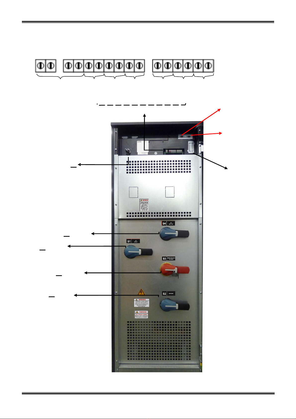
MAINTENANCE BYPASS SWITCH (MBS): This is a manually controlled mechanical switch, which is used
to supply the critical load, using the bypass source, when the UPS is shut down for maintenance or
troubleshootingpurposes.
The load is unprotected against mains supply disturbances and black-outs when it is connected to either
static or maintenance bypass supply.
1.2.2. OPERATING CONDITIONS OF UPS
UPS may be in one of the following operating
conditions:
A. Normal Operation (If Mains supply is available):
All fuses and power switches are closed (except the Maintenance Bypass Switch), and the load is supplied
by the Inverter Output. During normal operation, the Rectifier supplies DC power to the Inverter and charges
the Batteries at the same time.
B. Battery Operation :
The Batteries are connected to the Rectifier output. In case of a mains failure (mains power outage or AC
input voltage out of tolerance), the Rectifier stops operating and the DC voltage necessary for the inverter
operation is supplied by the batteries. Therefore the AC voltage output supplying the critical load is not
interrupted, until the batteries are fully discharged. At the end of the discharging time the inverter is turned
off and it start again automatically, together with the rectifier, when the mains power is restored, and the
UPS returns o normal operation. For UPS with a split bypass source, at the end of discharging time, static
transfer switch transfers the load to the split bypass source without interruption if the split bypass source is
available and in acceptable tolerances about voltage and frequency, as still the rectifier input is not available.
The Rectifier is also turned off and inverter operates on batteries during automatic or manual battery test
procedure.
C. By-Pass Operation :
If the Inverter output is overloaded or in case of a problem in the UPS, the static switch transfers the load to
the bypass supply without any interruption, provided that the bypass supply is available and within the
tolerated limits regarding voltage and frequency. At the end of the overloading period, if the fault condition
is restored, static switch transfers the critical load again to the inverter output. Note that, during operation
from the bypass supply, the critical load may be effected by any possible disturbances or power failure in
the bypass supply.

7
1.3 Front view of UPS Connection Panel
Batt. circuit
Generator
Temperature
Relay
Relay
Relay
breaker
input
Emergency sensor
2
3
4
output
and input
stop
Relay Output contacts COM1 -
RS232
Communation
Socket
(DB9
female)
COM2 -
RS232
Communation
Socket
(DB9
female)
S7
On/off
switch
SNMP
(Optional)
S4
(AC output,
F7-F8-F9)
S1
(AC input,
F1-F2-F3)
S3
(Maintenance
by-pass)
S2
(By-Pass,
F4-F5-F6)
Figure 1.3 a 100-120-160 kVA Switches, Fuses and Interface Connections

8
1.4 Technical Specifications
MODEL
PLT3100
PLT3120
PLT3160
Output (KVA)
100 kVA
120 kVA
160 kVA
Output (KW)
90
kW
108 kW
144 kW
Output Power Factor
0,9
INPUT
Number of Phases
3 Phase +
Neutral
Input Voltage
220/380, 230/400 or 240/415 Vac
Input Voltage Tolerance
+20% , -25% (+15% at 240/415Vac)
Input Power Factor (PF)
0,98 - 0,99 (at full load)
Input THDI
<= 5% (at full
load)
Input Frequency
50 Hz.
5%
By-pass Voltage
220/380, 230/400 or 240/415 Vac 3 Phase + Neutral
By-pass Frequency
50 Hz.
2%
RFI Level
EN62040-2
OUTPUT
Number of Phases
3 Phase +
Neutral
Output Voltage
220/380, 230/400 or 240/415 Vac
Output Voltage Tolerance
1%
Output Frequency
50
Hz.
Output Frequency Tolerance (Synchronous)
2%
Output Frequency Tolerance (Battery)
0,2%
Efficiency(100% Load)
up to
94%
Load Crest Factor
3:1
Output Voltage THD (linear load)
<3%
Overload
125% Load 10min. , 150% Load 1min.
BATTERY
Total Number
60 blocks 12V (2x30 serial 60 batteries, external)
Float Charge Voltage (250C)
405V
DC
End of Discharge Voltage
300V
DC
Battery Test
Automatic and Manual
Boost Charge
Available
COMMUNICATION INTERFACES
RS232 Com Port
2 each standard (COM1 and COM2)
External Temperature Measurement Input
Available (standard)
RS485 Comm. Port
Optional
Remote Monitoring Panel
Optional
SNMP Adapter
Optional
Modbus Adapter
Optional
Alarm Relay Contacts
4 each dry contacts (function programmable)8 optional
Digital Inputs
2 each
optional
EmergencyPower-Off Input
Available (standard)
ENVIRONMENT
Operating Temperature
0 –
40
0
C
Operating Humidity
<= %90 (non-condensing)
Acoustic Noise
< 68
dB
Dimensions (WxDxH) (mm)
515 x 855 x
1450
Device Type and Protection Class
Class 1 –
IP20
Weight (app. kgs)
216
230
258

9
II.
UPS INSTALLATION
2.1 Introduction
WARNING!!!
Do not apply electrical power to the UPS equipment before the arrival of authorized service
personnel.
The UPS equipment should be installed only by qualified service personnel.
The connection of the batteries and the maintenance should be done by qualified service
personnel.
Do not make any short- circuit to the battery poles. Because of high voltage and high short-
circuit current, there is risk of electrical shock or burn.
Eye protection should be worn to prevent injury from accidental electrical arcs. Remove rings,
watches and all metal objects. Only use tools with insulated handles. Wear rubber gloves.
This chapter contains location installation information of the UPS and the batteries. All the
establishments have their own specialties and needs. So in this part, the installation procedure is
not being explained step by step. Instead, general procedure and the applications are explained for
the technical personnel.
2.2 Unpacking
The UPS is packed and enclosed in a structural cardboard carton to protect it from damage.
1) Inspect for damage that may have occurred during the shipment If any damage is noted, call
the shipper immediately and retain the shipping carton and the UPS.
2) Carefully open the carton and take the UPS out.
3) Retain the carton and packing material for future use.
Unit package contents:
1) A user manual and Guarantee certificate.
2) Battery cabinet and/or shelf (Optional)
3) Batteryconnection cables.
2.3 Equipment Positioning
ATTENTION: Units are designed to operate on the concrete floor.
1. The equipment’s installation place must be an easy serving place.
2. Install the UPS in a protected area with adequate air flow and free of excessive dust.
3. You must therefore allow for a minimum gap of 250 mm behind the unit to allow adequate air
flow
4. Select a suitable place (temperature between 0 C and 40 C) and the relative humidity (%90
max)
5. It is recommended to place the equipment in an air-conditioned the room (24 C)
6. Temperature is a major factor in determining the battery life and capacity. Keep batteries away
from main heat sources or main air inlets etc.
7. In case of an operating the UPS in a dusty place, clean the air with a suitable air filtration
system.
8. Keep out of your equipment from explosive and flammable items.
9. Avoid direct sunlight, rain, and high humidity.
WARNING!!! Check the capacity of the forklift if it is available for lifting.
DO NOT LEAN OR LIFT THE BATTERY CABINET(S) AFTER THE BATTERIES
HAVE BEEN INSTALLED.

10
2.4 Connecting the UPS Power Cables
WARNING!!!A separate power line should be used to supply the UPS AC input. Never use the
same line to supply another electrical device. Do not use any additional cable to
increase the length of the UPS’s input cable. It is advised to use an MCCB suitable
for the input current on the UPS’s input line.
The connection of the electrical panel should be supplied by a grounded outlet. Otherwise,
the UPS and the load connected to the output will be left ungrounded. The grounding
system must be checked, and must be strengthen if required. Potential difference
between ground and neutral must be less than 3V AC.
Descriptions of the UPS input output cable connection terminals are shown in figure 2.2
Recommendedinput line cable and fuse ratings are given in the table below.
UPS
power
(kVA)
Recommended cable size (mm2)
Line input
Bypass input /
UPS output
External Battery
AC Input
/AC
Output
Cable
Terminals
U-V-W-N
Battery
Terminals
+ & -
100
50
35
35
M8 bolt
M8 bolt
120
50
50
50
M8 bolt
M8 bolt
160
70
70
70
M8 bolt
M8 bolt
NOTES: The neutral conductor should be sized for 1,5 times the output/bypass phase current. These
recommendations are for guideline purposes only and are superceded by local regulations
and codes of practice.
2.5 Safety Earth
The safety earth cable must be connected to the earth BUS BAR and bonded to each cabinet in
the system and also the earthing and neutral bonding arrangements must be in accordance with
the local laws.
ATTENTION!!! Failure to follow adequate earthing procedures can result in electric shock hazard to
personnel, or the risk of fire.
2.6 Cable connection procedure
WARNING!!! All connections of the UPS must be done by qualified service personnel
After positioning the UPS, the cables must be connected as described below:
1. Verify all switches and fuses in front of the UPS are at “0” position. (OFF)
2. Connect the 3 phase AC input coming from the mains distribution panel to the AC input terminals as
shown on the label. (Figure 2.2)
ATTENTION!!!: ENSURE CORRECT PHASE SEQUENCE.
If there is a phase sequence error, UPS doesn’t transfer the load to INVERTER output. If
you can’t see SYNC:OK in the INFORMATION MENU on LCD, then change the input phase sequence.
3. Connect the output of the UPS to the load distribution panel.
4. Connect the battery groups. Refer to battery installation section.

11
WARNING :
- CHECK BOTH OF THE BATTERY GROUPS FOR CORRECT POLARITY AND VOLTAGE
- DO NOT TURN ON THE BATTERY SWITCH (F5) BEFORE STARTING THE UPS
5. Connect the copper earth bus, to the safety earth of the mains distribution panel.
NOTE : The earth and the neutral connections must be in accordance with the local rules.
WARNING: Note that the Input Neutral (N1) MUST also be connected to K10 terminal
2.6.1 UPS Power Cable Connection Terminals :
Figure 2.2 100-120-160 kVA POWER Cable Connection

12
NOTES :
As shown on the power cable connection diagram of the UPS, U1, V1 and W1 phase of the incoming 3
phase supply are used as the bypass inputs under normal conditions, if there is not a separate bypass
supply (split bypass). (U1, V1, W1 and U2, V2, W2 are the same in this case)
If there is a separate 3- phase AC supply for bypass (Split Bypass):
a-) Remove the links between K4-K5, K6-K7, and K8-K9
b-) Connect the phases of the bypass source U2, V2 and W2 to the indicated terminals (K5,K7,K9)
c-) Connect the Neutral (N2) of the Bypass source to K11. (Neutral Busbar)
Note that the Neutral of the 3 phase input supply (N1) and the Neutral of the 3-phase bypass supply (N2)
must always be connected together to form the Neutral of the AC output.
2.7 Battery Installation
WARNING!!! Be careful while connecting batteries.
ATTENTION!!! Open the battery switch/fuse before making any connection on the batteries.
The batteries associated with the UPS equipment are usually contained in a purpose-built battery cabinet.
External batteries are used in PLT300 Series 100,120 and 160 kVA UPSs, there is no space for internal
batteries in UPS cabinet.
Where battery racks are used, they should be sited and assembled in accordance with the battery
manufacturer’s recommendations. In general, batteries require a well-ventilated, clean and dry environment
at reasonable temperatures to obtain efficient battery operation.
In general a minimum space of 10 mm must be left on all vertical sides of the battery block. A minimum
clearance of 20 mm should be allowed between the cell surface and any walls. All metal racks and cabinets
must be earthed.
1. Unpack each battery and check its terminal voltage with a suitable load. Any battery with terminal
voltage less than 10,5V must be charged before installation.
2. Please check the battery connecting hardware and documents. (cables, trays, connection diagrams)
3. Please locate suitable number of batteries on each rack, according to the battery installation and
connection diagram given with the unit.
4. Start locating the batteries from top to the bottom on the racks.
5. Be careful about the connection between the racks and polarities.
6. After interconnecting the batteries, connect “+”, “0” and “-“leads of the batteries to the battery input
terminals on the UPS. Be careful to connect the batteries correctly and do not turn on (S5) before
checking all connections and before starting the UPS. In PLT300 Series UPS, 60 blocks of batteries are
connected in series, in such a way that they form two strings of batteries with opposite polarity; with a
center tap connection to the NEUTRAL (N1-N2) internally.
NOTE THAT SEPARATE CABLES FROM EACH BATTERY GROUP SHOULD BE CONNECTED TO K2
TERMINALS TO FORM THE MIDPOINT CONNECTION.
WARNING!!! NEVER TURN ON S5 (BATTERY SWITCH) (OR CONNECT BATTERY FUSES F10, F12)
WITHOUT CENTER POINT CONNECTION TO K2.

13
K1 K2K2 K3
( + )
+
-
+
-
+
-
+
-
+
-
+
-
+
-
+
-
+
-
+
-
360V
30x12V
Batteries
30x12V
Batteries
( 0 ) ( 0
360V ( - )
Figure 2.3 External Battery Connections (60x12V)

14
III.
FRONT PANEL
3.1 Introduction
The front panel of UPS, consisting of a 4 lines alphanumeric display, 7 status lamps, plus 5 function keys,
allows the complete monitoring of the UPS status. The mimic flow diagram helps to comprehend the
operating status of the UPS. By using the function keys operator can moves on menus and change some
parameters.
Figure 3.1 Control panel oft he
UPS
L1 : Maintenance bypass switch on indicator lamp
L2 : Load on bypass indicator lamp
L3 : Input voltage indicator lamp
L4 : Rectifier run pilot lamp
L5 : Battery operation indicator lamp
L6 : Load on UPS indicator lamp
L7 : Output switch on indicator lamp
There are 5 control buttons on the UPS Front panel ,ENTER button provides selection decleration,up and
down buttons provides to surf on menus, (+) and (-) buttons are used for adjustments or option selection.
3.2 Front Panel Menu Descriptions :
By using ( ), ( ) and ENTER buttons you can access the following menus. At the end of each menu there
is <ENTER> EXIT message will be showed, if you press enter you will exit to upper menu. All menus have
3 or 4 levels.

15
Main menu (Level 1)
Menu
Usage
1
STATUS
Enter Status menu
2
MEASUREMENTS
Enter Measurements menu
3
ALARM LOGS
Enter Alarm logs menu
4
INFORMATION
Enter Information menu
5
OPTIONS
Enter Options menu
6
COMMAND
Enter Command menu
7
TIME
Enter Time menu
8
SERVİCE
Enter Service menu
9
PASSWORD
Enter Password screen
10
ADJUST
Enter Adjust menu
Goto 1
Sub menus (Level 2)
Level 1
Level 2
Page
Level 3
STATUS
Status of the UPS
MEASUREMENTS
INPUT
Input measurements
BYPASS
Bypass measurements
INVERTER
Inverter measurements
OUTPUT
Output measurements
DC
DC measurements
GENERAL
General measurements
ENTER - EXIT
ALARM LOGS
UPS LOG RECORD
Page1
ENTER CLEAR LOG
Page1
ENTER - EXIT
INFORMATION
RS232 Comm 1:-- 2:--
Page1
Maximum UPS power
Page1
Nominal voltage and frequency
Page1
Inverter firmware version
Page2
PFC firmware version
Page2
Panel firmware version
Page2
UPS Model
Page3
Communicationprotocol
Page3
Chassis nr
Page3
ENTER - EXIT
OPTIONS
LCD OPTIONS
LCD panel options
COMM.OPTIONS
Communicationoptions
ALARM OPTIONS
Alarm options
BYPASS OPTIONS
Bypass options
ENTER - EXIT
COMMAND
By-pass transfer
Page1
Boost charge start
Page1
Short battery test start
Page1
Relay check
Page2
Dialup modem programming
Page2
Alarm sound ON/OFF
Page3
Warning sound interval
Page3
ENTER - EXIT
TIME
Current time
Page1
Current date
Page1
Set hour
Page2
Set minute
Page2
Set day
Page3

16
Level 1
Level 2
Page
Level 3
Set month
Page3
Set year
Page3
Update time and date
Page4
ENTER - EXIT
SERV
İ
CE
Operating hourmeter
Page1
Maximum load
Page1
ENTER Fault reset
Page1
Fan maintenance hourmeter
Page2
Batt.maintenancehourmeter
Page2
General maintenance hourmeter
Page2
Logout command
Page3
ENTER - EXIT
PASSWORD
Getting service code
Page1
Type service password
Page1
Type user password
Page1
ENTER - EXIT
ADJUST
(in English)
Group adjustments
Automatic settings
Inverter factory options
Options list
Rectifier factory options
Options list
Panel adjustments
Options list
AC input adjustments
AC input settings
AC Bypass adjustments
AC bypass settings
AC output adjustments
AC output settings
DC adjustments
DC settings
Power adjustments
Power settings
ENTER - EXIT

17
3.2.1 MEASUREMENTS menu
All mesasured values of the UPS can be monitored from this menu.
Use up and down buttons to move on submenu
MEASUREMENTS/ INPUT (Level 2)
All rectifier input measurements are located in this menu, use up and down buttons to move on submenu
MEASUREMENTS / INPUT Page 1 (Level 3)
P-N L1 L2 L3
Page header
Vinp: 221/222/223 V
Phase to neutral measured AC input voltages
Iinp: 000/000/000 A
Measured RMS AC input phase currents
……………………………..
Current alarm messages
Up previous page ,down next page
MEASUREMENTS / INPUT Page 2 (Level 3)
P-P L13 L21 L32
Page header
Vinp: 381/382/383 V
Phase to phase measured AC input voltages
Finp: 49.6 Hz
Measured rectifier input frequency
……………………………..
Current alarm messages
Up previous page ,down next page
MEASUREMENTS / INPUT Page 3 (Level 3)
ENTER - EXIT
ENTER exit to upper menu
……………………………..
Current alarm messages
Up previous page, down next page
MEASUREMENTS/ BYPASS (Level 2)
All by-pass input measurements are located in this menu, use up and down buttons to move on submenu
MEASUREMENTS / BYPASS Page 1 (Level 3)
P-N L1 L2 L3
Page header
Vbyp: 221/222/223 V
Phase to neutral measured AC bypass input voltages
OK OK --
Bypass voltage status
……………………………..
Current alarm messages
Up previous page, down next page
MEASUREMENTS / BYPASS Page 2(Level 3)
P-P L13 L21 L32
Page header
Vbyp: 381/382/383 V
Phase to phase measured AC bypass input voltages
Fbyp: OK / 50.0 Hz
Measured bypass input frequency
……………………………..
Current alarm messages
Up previous page, down next page
MEASUREMENTS / BYPASS Page 3(Level 3)
ENTER - EXIT
ENTER exit to upper menu
……………………………..
Current alarm messages
Up previous page, down next page
Table of contents
Other EPC Power Supply manuals
Popular Power Supply manuals by other brands

Elvox
Elvox 6946 Wiring instructions

TDK-Lambda
TDK-Lambda LZS-A1000-3 Installation, operation and maintenance manual

TDK-Lambda
TDK-Lambda 500A instruction manual

Vimar
Vimar Elvox 6837/C17 Installer's guide

Bentel Security
Bentel Security BXM12/30-U quick start guide

Vertiv
Vertiv NetSure 5100 Series user manual