Epic Fans Brevis User manual

User’s Manual
Installation, Operations,
Maintenance and Parts
Part No. 6022110A
Do not install, operate or service this product unless you
have read and understand the Safety Practices, Warnings,
and Installation and Operating Instructions contained in
this User’s Manual. Failure to do so could result in death
or serious injury.
This manual applies to fans
manufactured beginning March
2019.
Brevis 3 Blade HVLS Fan
User’s Manual
E506041

2 6022110A — 3 Blade HVLS Fans April 2019
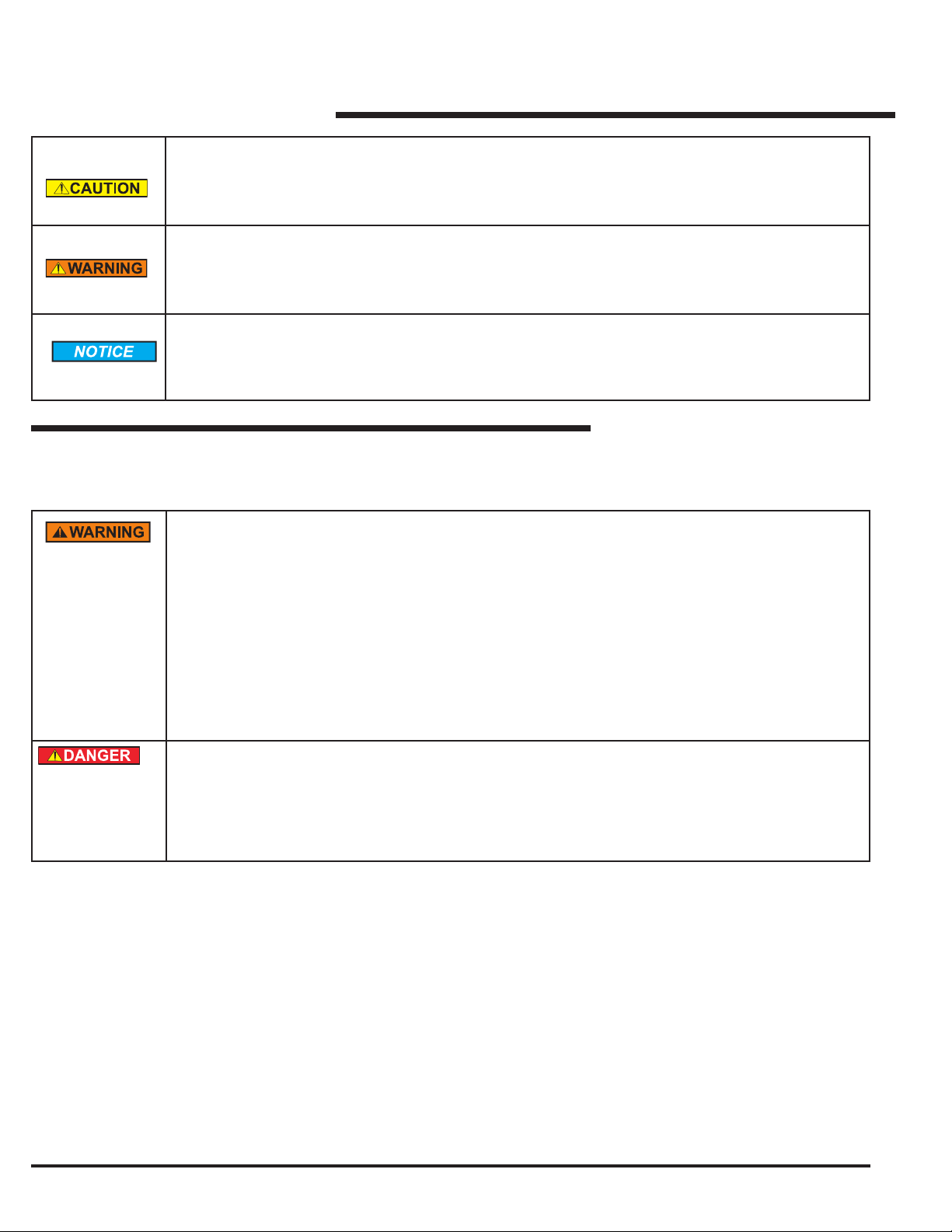
You may nd safety signal words such as DANGER, WARNING, CAUTION or NOTICE throughout this User’s
Manual. Their use is explained below:
SAFETY SIGNAL WORDS
Introduction.................................................................2
Safety Signal Words ..................................................2
Safety Practices..........................................................3
Owner’s Responsibilities ............................................5
Hardware....................................................................6
Fan Kit ........................................................................7
Installation Considerations .........................................8
Installation ................................................................12
Components and Specications...............................19
table of contents
Operating Instructions ..............................................20
Planned Maintenance...............................................21
Troubleshooting Guide .............................................22
VFD Fault Codes......................................................23
Fire Control System Fan Shutdown..........................25
Electrical Schematics ...............................................28
Parts List...................................................................31
Warranty Information ................................................32
Distributor Information ..............................................32
INTRODUCTION
Welcome and thank you for choosing this 3-Blade HVLS fan from Epic Fans.
This User’s Manual contains information that you need to safely install, operate and maintain the fan. It also
contains a complete parts list and information about ordering replacement parts. Please keep and read this User’s
Manual before using your new fan.
WARNING AND CAUTION SYMBOL
THIS IS THE SAFETY ALERT SYMBOL. IT IS USED TO ALERT YOU TO POTENTIAL
PERSONAL INJURY HAZARDS. OBEY ALL SAFETY MESSAGES THAT FOLLOW
THIS SYMBOL TO AVOID POSSIBLE DEATH OR INJURY.
DANGER SYMBOL
INDICATES AN IMMINENTLY HAZARDOUS SITUATION WHICH, IF NOT AVOIDED,
WILL RESULT IN DEATH OR SERIOUS INJURY
ELECTRICAL WARNING SYMBOL
INDICATES AN ELECTRICAL HAZARD WITH A MEDIUM LEVEL OF RISK THAT
COULD RESULT IN DEATH OR SERIOUS INJURY.
April 2019 6022110A — 3 Blade HVLS Fans 3
CAUTION SYMBOL
INDICATES A POTENTIALLY HAZARDOUS SITUATION, WHICH IF NOT AVOIDED
MAY RESULT IN MINOR OR MODERATE INJURY.
WARNING SYMBOL
INDICATES A POTENTIALLY HAZARDOUS SITUATION WHICH, IF NOT AVOIDED,
COULD RESULT IN DEATH OR SERIOUS INJURY.
NOTICE SYMBOL
NOTICE IS USED TO ADDRESS PRACTICES NOT RELATED TO PERSONAL
INJURY.
IMPORTANT SAFETY INSTRUCTIONS
READ AND SAVE THESE INSTRUCTIONS
READ THESE SAFETY PRACTICES BEFORE INSTALLING, OPERATING, OR
SERVICING THE FAN. FAILURE TO FOLLOW THESE SAFETY PRACTICES
COULD RESULT IN DEATH OR SERIOUS INJURY.
READ AND FOLLOW THE OPERATING INSTRUCTIONS IN THIS MANUAL
BEFORE OPERATING THE FAN. IF YOU DO NOT UNDERSTAND THE
INSTRUCTIONS, ASK YOUR SUPERVISOR TO TEACH YOU HOW TO USE THEM
TO REDUCE THE RISK OF PERSONAL INJURY, DO NOT BEND THE BLADE
BRACKETS WHEN INSTALLING THE BRACKETS OR CLEANING THE FAN. DO
NOT INSERT FOREIGN OBJECTS IN BETWEEN ROTATING FAN BLADES.
TO REDUCE THE RISK OF FIRE, HVLS FAN MOTOR ASSEMBLIES MUST BE
INSTALLED WITH THE BLADE ASSEMBLIES THAT ARE MARKED ON THEIR
CARTONS TO INDICATE THE SUITABILITY WITH THIS MODEL. OTHER BLADE
ASSEMBLIES CANNOT BE SUBSTITUTED.
BE CERTAIN TO FOLLOW THE INSTRUCTIONS IN THIS MANUAL.
4 6022110A — 3 Blade HVLS Fans April 2019
INSTALLATION OF THE EQUIPMENT MUST COMPLY WITH LOCAL AND NATIONAL
ELECTRICAL CODES AND MUST BE IN ACCORDANCE WITH ANSI/NFPA 7-1999.
DO NOT USE THIS INDUSTRIAL FAN UNTIL YOU HAVE RECEIVED PROPER
TRAINING. IMPROPER USE COULD RESULT IN PROPERTY DAMAGE, BODILY
INJURY AND/OR DEATH. READ AND FOLLOW THE COMPLETE OPERATING
INSTRUCTIONS ON PAGES 20AND 21 BEFORE USE. IFYOU DO NOT UNDERSTAND
THE INSTRUCTIONS, ASK YOUR SUPERVISOR TO EXPLAIN THEM TO YOU OR
CALL YOUR LOCAL DISTRIBUTOR.
DO NOT USE THE FAN IF IT APPEARS DAMAGED OR DOES NOT OPERATE
PROPERLY. INFORM YOUR SUPERVISOR IMMEDIATELY.
DO NOT OPERATE THE FAN UNTIL ALL PERSONNEL, BUILDING STRUCTURE,
AND EQUIPMENT ARE CLEAR OF ALL MOVING PARTS AND EXCLUSION ZONES.
INSTALL GUARDS AS REQUIRED.
TO REDUCE THE RISK OF ELECTRICAL SHOCK, DO NOT EXPOSE TO WATER OR
RAIN.
SUPPORT DIRECTLY FROM BUILDING STRUCTURE. DO NOT INSTALL THE
FAN UNIT ONTO STRUCTURE OF INSUFFICIENT STRENGTH. CONSULT
A PROFESSIONAL ENGINEER OR REGISTERED ARCHITECT. IMPROPER
INSTALLATION OF THE FAN COULD RESULT IN DEATH OR SERIOUS INJURY.
BEFORE SERVICE, INSPECTION, OR CLEANING, MAKE CERTAIN THE POWER IS
DISCONNECTED AND PROPERLY LOCKED OUT.
IF THE FAN DOES OPERATE PROPERLY USING THE PROCEDURES IN THIS
MANUAL, BE CERTAIN TO REMOVE POWER FROM THE UNIT AND LOCK-OUT
THE DISCONNECT ON THE POWER CIRCUIT. CALL YOUR LOCAL DISTRIBUTOR
FOR SERVICE.
KEEP YOUR BODY CLEAR OF MOVING PARTS AT ALL TIMES.
ALL ELECTRICAL TROUBLESHOOTING AND REPAIR MUST BE DONE BY A
QUALIFIED TECHNICIAN AND MEET ALL APPLICABLE CODES.
IF IT IS NECESSARY TO MAKE TROUBLESHOOTING CHECKS INSIDE THE VFD
BOX WITH THE POWER ON, USE EXTREME CAUTION. DO NOT PLACE FINGERS
OR UN-INSULATED TOOLS INSIDE THE ENCLOSURE. TOUCHING WIRES OR
OTHER PARTS INSIDE THE ENCLOSURE COULD RESULT IN ELECTRICAL
SHOCK. DEATH, OR SERIOUS INJURY.
VARIABLE FREQUENCY DRIVE (VFD) FAN CONTROLLERS CONTAIN HIGH
VOLTAGE CAPACITORS. BEFORE WORKING ON THE FAN CONTROLLER,
ENSURE ISOLATION OF THE MAIN VOLTAGE SUPPLY AND VERIFY VOLTAGE
HAS BLED OFF PRIOR TO BEGINNING WORK. FAILURE TO DO SO MAY RESULT
IN DEATH OR SERIOUS INJURY.
IF YOU HAVE PROBLEMS OR QUESTIONS, CONTACT YOUR LOCAL DISTRIBUTOR
FOR ASSISTANCE.

April 2019 6022110A — 3 Blade HVLS Fans 5
TO REDUCE THE RISK OF INJURY TO PERSONS, INSTALL FAN SO THAT THE
BLADE IS AT LEAST 3.05M (10') ABOVE THE FLOOR.
INSTALLATION WORK AND ELECTRICAL WIRING MUST BE DONE BY QUALIFIED
PERSON(S) IN ACCORDANCE WITH ALL APPLICABLE CODES AND STANDARDS.
WHEN CUTTING OR DRILLING INTO WALL OR CEILING, DO NOT DAMAGE
ELECTRICAL WIRING AND OTHER HIDDEN UTILITIES.
EXERCISE CAUTION AND COMMON SENSE WHEN POWERING THE FAN. DO NOT
CONNECT THE FAN TO A DAMAGED OR HAZARDOUS POWER SOURCE. DO NOT
ATTEMPT TO RESOLVE ELECTRICAL MALFUNCTIONS OR FAILURES ON YOUR
OWN.
WHEN SERVICE OR REPLACEMENT OF A COMPONENT IN THE FAN REQUIRES
THE REMOVAL OR DISCONNECTION OF A SAFETY DEVICE, THE SAFETY DEVICE
IS TO BE REINSTALLED OR REMOUNTED AS PREVIOUSLY INSTALLED.
RISK OF FIRE, ELECTRIC SHOCK, OR INJURY TO PERSONS DURING CLEANING
AND USER-MAINTENANCE. DISCONNECT THE FAN FROM THE POWER SUPPLY
BEFORE SERVICING.
STAY ALERT, WATCH WHAT YOU ARE DOING, AND USE COMMON SENSE
WHEN INSTALLING FANS. DO NOT INSTALL FANS WHEN TIRED, OR UNDER
THE INFLUENCE OF DRUGS, ALCOHOL, OR MEDICATIONS. A MOMENT OF
INATTENTION WHILE INSTALLING FANS MAY RESULT IN SERIOUS PERSONAL
INJURY.
THE INSTALLATION OF THIS FAN REQUIRES THE USE OF SOME POWER TOOLS.
FOLLOW THE SAFETY PROCEDURES FOUND IN THE OWNER'S MANUAL FOR
EACH OF THESE TOOLS AND DO NOT USE THEM FOR PURPOSES OTHER THAN
INTENDED BY THE MANUFACTURER.
OWNER’SRESPONSIBILITIES
The owner’s responsibilities include the following:
The owner should recognize the inherent danger of the interface between the 3 Blade fan and shop worker. The owner
should, therefore, train and instruct operators in the safe use of the 3 Blade fan.
Nameplates, cautions, instructions and posted warnings shall not be obscured from the view of operating or maintenance
personnel for whom such warnings are intended. Warnings which are worn or non-legible should be replaced.
Manufacturer’s recommended periodic maintenance and inspection procedures in eect a t d ate o f s hipment s hall be
followed, and written records of the performance of these procedures should be kept.
3 Blade fans that are structurally damaged or have experienced impacts from external sources, shall be removed from
service, inspected by the manufacturer’s authorized representative, and repaired as needed before being placed back in
service.
The owner shall see that all nameplates and caution and instruction markings or labels are in place and that the
appropriate operating and maintenance manuals are provided to users.
Modifications or alterations of 3 Blade fans shall be made only with written permission of the original manufacturer.

6 6022110A — 3 Blade HVLS Fans April 2019
HARDWARE
(x4) 1/2-13UNC x 2-1/2
Mount ─ Building
(x4) 1/2-13UNC lock nut
Guy wire assembly
Safety cable
(x20) 3/8-16UNC lock nut
Mount ─ Blade
Identification labels
Fan information
Fan diameter
Operating instructions
Fastener torque requirements
Description Torque Wrench size
1/2 dia mount hardware 44-48 ft-lbs. 3/4 hex
3/8 dia blade mount hardware 24-28 ft-lbs. 9/16 hex
Cable clamp, guy wire Secure tight 5/16 nut driver
Cable clamp, safety cable Secure tight 1/2 nut driver
(x4) 1/2-13UNC x 1-1/4 bolt
(x4) 1/2-13UNC lock nut
Mount ─ Motor frame
(x2) 1/2-13UNC x 4-1/2 bolt
(x4) 1/2 dia. washer
(x2) 1/2-13UNC nyloc lock nut
Mount ─ Assembly
NOTE:
Additional spare hardware is provided as a courtesy.

April 2019 6022110A — 3 Blade HVLS Fans 7
PACKING KIT (Standard)
1. Blade Box – 3 each
2. Fan Motor Box
a. Motor/gearbox assembly.
b. Mounting hardware. See page 5.
c. VFD box.
REQUIRED TOOLS
• Wrenches: 9/16, 3/4 (x2), 1/2
• Sockets: 1/2, 9/16, 3/4
• Nut drivers: 5/16
• Torque wrench: 15-60 Ft-lbs (for use with sockets)
• Wire strippers
• 1/4" cable cutter
• Tape measure
• Spirit level, short
• Gloves
•For laminated wood beam installs, a drill and 1/2" dia.
drill bit are required.
PRIOR TO FAN INSTALLATION:
1. Ensure that the supplied voltage matches the fan
voltage. A label containing voltage information specic
to the individual fan is located on the side of the VFD
box.
2. Ensure all mounting hardware shown on page 5 is
present.
FAN KIT
NATIONAL FIRE PROTECTION
ASSOCIATION STANDARD
In accordance with NFPA 13 Standard from the National Fire
Prevention Association as referenced in sections 12.1.4 and
11.1.7: High Volume Low Speed (HVLS) Fans: The installation
of HVLS fans in buildings equipped with sprinklers, including
ESFR sprinklers, shall comply with the following:
• The maximum fan diameter shall be 24 feet (6.1 m).
• The fan shall be approximately centered between four
adjacent sprinklers.
• The vertical clearance from the fan to sprinkler deector
shall be a minimum of 3 feet (0.9 m).
• All fans shall be interlocked to shut down immediately
upon receiving a water ow signal from the alarm system
in accordance with the requirements of NFPA 72- National
Fire Alarm and Signaling Code.

8 6022110A — 3 Blade HVLS Fans April 2019
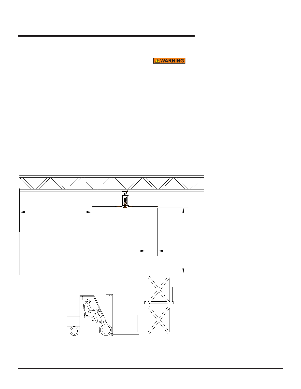
INSTALLATION CONSIDERATIONS
ROOF SLOPE
NOTE:
For roof angles in excess of 20°, consult factory. The extension
lengths shown are minimum recommendations only, based
solely o roof pitch and fan diameter. Other considerations
must be evaluated when determining extension requirements,
such as placement of lights, sprinkler systems, HVAC
systems, etc. In addition, OSHA requirements state that fan
blades must be a minimum of 10' above the oor.
NOTE:
All fan blade parts must be greater
than 3' from all obstructions
including lights, cables, sprinklers
and other building components and
greater than one (1) fan diameter
from any wall to blade tip.
Failure to maintain exclusion
zones outlined on pages 7,
8 and 9 could result in fan
failures, including blade
separation, which could result
in death or serious injury.
DO NOT operate fans when
physical obstructions or HVAC
air ows extend into exclusion
zones. Regularly inspect fans
to ensure exclusion zones
remain clear of interference
before operating fan.
*Consult factory for assistance with fan placement and extension selection.
Fig. 1
300
300
300
Roof Slope* 2/12 4/12
Roof Angle* 9.5° 18.4°
Fan Diameter (Ft)
12 5 76
16 8 10
20 10 12
Hanging
Weight
(Lb)
Maximum
Torque
(Ft. Lb)
165
170
180
0
0
5
6
7
3/12
14.0°
9
11
Blade length (In.)
45.16
69.16
93.16
Distance from ceiling (Ft)

April 2019 6022110A — 3 Blade HVLS Fans 9
INSTALLATION CONSIDERATIONS,continued
CLEARANCE FROM HVAC EQUIPMENT
For applications near HVAC equipment (diusers, radiant
heaters, exhaust fans, louvers, etc.), the HVLS fan must be
installed at minimum distances.
• Fans located at or above HVAC equipment must have
a minimum clearance of greater than or equal to 1 fan
diameter. See Fig. 2.
• Fans located below HVAC equipment must have a minimum
clearance of greater than or equal to 2 fan diameters. See
Fig. 3.
Failure to maintain exclusion zones outlined on pages
7, 8 and 9 could result in fan failures, including blade
separation, which could result in death or serious injury.
DO NOT operate fans when physical obstructions or
HVAC air ows extend into exclusion zones. Regularly
inspect fans to ensure exclusion zones remain clear of
interference before operating fan.
Fig. 2
Fig. 3
Greater than
1 fan dia.
Greater than
2 fan dia.
10 6022110A — 3 Blade HVLS Fans April 2019
Failure to maintain exclusion zones outlined on pages
7, 8 and 9 could result in fan failures, including blade
separation, which could result in death or serious injury.
DO NOT operate fans when physical obstructions or
HVAC air ows extend into exclusion zones. Regularly
inspect fans to ensure exclusion zones remain clear of
interference before operating fan.
CLEARANCE FROM SOLID OBSTRUCTIONS
For applications near solid obstructions the HVLS fan must
be installed at minimum distances.
• Fans located above solid obstructions such as racks, walls,
etc. must have a minimum vertical clearance of greater than
or equal to 1/2 fan diameter above and less than or equal
to 1/4 fan diameter inside the fan blade arc. See Fig. 4.
Fig. 4
INSTALLATION CONSIDERATIONS,continued
Greater than
1/2 fan dia.
Less than
1/4 fan dia.
Greater than
1/2 fan dia.

April 2019 6022110A — 3 Blade HVLS Fans 11
INSTALLATION CONSIDERATIONS,continued
BUILDING STRUCTURE
For open structure roof designs, the fan should only be hung
from either I-beam or angle iron. Do not hang from purlins,
joists or truss structure.
For solid beam or laminated wood beam mounting, use
the laminated wood beam mounting kit available from
Epic Fans.
Consult a professional engineer or registered architect for
specic mounting concerns.
Ensure fan blade clearance meets the requirements. See
Fig. 1-4.
PLACEMENT AND SPACING
Consult your local distributor to help you plan the most
ecient installation of your fans.
Ensure fan placement is such that the fans blades are a
minimum of 10' from any manned working surface (oor or
mezzanine
Ensure fan blade does not extend into exclusion zone.
Extensions are available if required. See Fig. 1.
Avoid mounting fans directly under lights or skylights to
avoid visual strobing aect.
NOTE:
Be certain to comply with all local and national codes during
installation.
For fans that will be subjected to high cross winds (open
bay doors or air conditioning diuser ducts) the fan must
be at least two fan diameters (as measured from the end
of the winglet) from open bays or A/C ducts mounted
below the blade plane.
Fig. 5
1/2-13UNC x 4-1/2 (x2)
1/2 dia washer (x2)
Pivot bracket
Mount tube
Hardware should be GRADE 5 or better.

12 6022110A — 3 Blade HVLS Fans April 2019
INSTALLATION
Fig. 7
Building structure
Clamp plate
Shim
Fig. 6
Pivot bolt
Shim (x2)
(as req’d)
1/2-13UNC x 2-1/2 bolts (x4)
1/2-13UNC
lock nut (x4)
Angle
adjustment
bolt
Before installation, make certain that the power is
disconnected and properly locked out.
FAN MOUNT ASSEMBLY
1. Fasten pivot brackets to the extension tube with ears
outboard. Leave the 1/2" dia. x 4-1/2" bolts and nylock
nuts nger tight. See Fig. 5.
INSTALL FAN MOUNT
STANDARD I-BEAM
1. Locate fan mount assembly on bottom of building
support beam. Align mount assembly so that it is
centered and square to the beam.
2. Install clamps. For thick ange I-beams add shims as
required. Fasten using the supplied 1/2" dia x 2-1/2"
screws, lock nuts and washers. Torque to 44-48 ft-lbs.
See Fig. 7.

April 2019 6022110A — 3 Blade HVLS Fans 13
If building support beam is not level, ensure proper fan
clearance using the mounting information shown on
pages 7-9 or add mounting extensions as required to
ensure clearance. See Fig. 1.
LAMINATED WOOD BEAM MOUNTING —
(OPTIONAL KIT 6018641)
1. Attach laminated wood beam brackets to the wooden
beam using a minimum of four 1/2" dia. grade 5 thru
bolts and self-locking nuts (not supplied). Ensure
brackets are square to the bottom of the beam.
2. Attach mount assembly to the laminated wood beam
brackets using the supplied 1/2" dia x 2-1/2" screws,
nylock lock nuts and washers. Torque to 44-48 ft-lbs.
See Fig. 8.
TRUSS MOUNT
NOTE:
Do not span distances greater than 96".
To span two trusses with a distance of 96" or less, span the
gap using two 4" x 4" x 1/4" steel angle iron. See Fig. 9.
Consult a professional engineer or registered architect for
specic mounting concerns.
NOTE:
Drill Holes in appropriate locations to maintain proper
exclusion zone clearance.
NOTE:
Longest extension allowed is 20'. Any extensions longer than
12' must use the secondary guy wire kit (6020303 — standard
or 60020304 — stainless steel).
INSTALL POWERHEAD (MOTOR/GEARBOX ASSY)
NOTE:
Leave the protective bumper on the bottom of the power head
assembly until the power head is mounted in place.
1. Using a powered lift, orient the powerhead with the
blade hub down. Block motor as required for installation
using the bottom of the frame assembly. Do not support
using the hub or hub cap.
Fig. 8
INSTALLATION,continued
Laminated wood
beam bracket
Laminated wood beam
Fig. 9
Fig. 10

14 6022110A — 3 Blade HVLS Fans April 2019
Fig. 11
Fig. 12
NOTE:
Fan powerhead may be oriented as required for aesthetics
or commonality.
2. Raise the powerhead up until it contacts the bottom of
the fan mount assembly. See Fig. 11.
3. Fasten the powerhead to the mount assembly using
the supplied 1/2" dia x 1-1/4" bolts, self-locking nuts
and washers. Torque to 44-48 ft-lbs. See Fig. 12.
4. Immediately attach safety cable. See Fig. 13.
a. Slide two of the supplied 1/4" dia cable clamps over
each end of the cable spaced 6" apart.
b. Slide the ends through the cable clamps.
c. Make sure that the cable goes through the motor
frame. See Fig. 13.
e. Securely tighten the clamp fasteners. Make sure
the u-bolts are over the free ends of the cable.
f. Ensure assembly does not interfere with fan motor
housing.
Mount tube
Powerhead
1/2-13UNC x 1-1/4
bolt (x4)
1/2-13UNC
lock nut (x4)
Fig. 13
Safety cable
Motor frame
Space cable
clamps 6" apart
INSTALLATION,continued

April 2019 6022110A — 3 Blade HVLS Fans 15
INSTALLATION,continued
Fig. 14
Seal removal note
Plastic
shipping
seal
Ventillation
plug
GEARBOX VENT PLUG
1. Locate ventilation plug on gearbox. See Fig. 19.
2. Pull and remove plastic shipping brace and discard.
3. Remove the plastic cseal.
4. Remove orange brace removal note and discard.
INSTALL GUY WIRES
Guy wires are designed to constrain lateral movement of
the fan in operation. This movement may be due to impacts
on the fan or winds impinging on the blades that would
cause the fan to sway.
Failure to attach guy wires may result in loss of
warranty.
If a mounting extension has been used, ensure that
the longer guy wires accompanying the extension are
used. Ensure that the angle formed by the guy wire
with the roof structure is less than 45º. See Fig. 15.
Avoid any sharp edges or corners to reduce fatiguing
and fraying of the guy wires. Failure to attach guy
wires may result in severe injury or death.
1. Adjust turnbuckles to their longest position.
2. Attach the quick link with attached turnbuckle to the fan
as shown. Repeat for all four quick links.
3. Attach one end of the guy wire to the building structure.
Repeat for all four guy wires.
a. Slide two of the supplied 1/8" dia cable clamps over
one end of the wire.
b. Feed that end of the wire though the building
structure and back through the clamp fasteners.
c. Securely tighten the clamp fasteners so that it
cannot slip. Make sure the u-bolts are over the free
end of the cable.
4. Individually tighten the turn buckle on each cable
until each cable is taut and the powerhead unit hangs
<45º
Fig. 16
Fig. 15
Guy wires
Quick link
Turnbuckle

16 6022110A — 3 Blade HVLS Fans April 2019
Fig. 17
Fig. 19
Fig. 18
Spread slightly
Blade retention
lock nuts
plumb. Use a spirit level to verify powerhead unit hangs
plumb.
5. Tighten pivot and angle adjustment bolts on fan mount.
Torque to 44-48 ft-lbs. See Fig. 6.
INSTALL BLADES
To reduce the risk of personal injury, do not bend the
blade brackets when installing the brackets or cleaning
the fan. Do not insert foreign objects in between
rotating fan blades.
NOTE:
Blade assemblies come pre-assembled from the factory. Do
not attempt to disassemble.
1. The hub assembly has special blade retention lock nuts
pre-assembled to it. Remove them now and use them
to mount the blade assemblies in the steps below. Use
only the factory supplied lock nuts provided for blade
mounting.
2. With the blade oriented such that the blade retention
lanyard is on top, support the blade assembly from
below. Orient and guide the assembly onto the top
attachment studs on the hub assembly. Spread the
strut arms slightly onto the upper studs as shown.
Angle the blade upward as needed to slide blade onto
studs. See Fig. 16.
3. Still supporting the blade assembly, rotate the blade
assembly down as shown and allow the bottom blade
strut to ride up and over the bottom attachment studs
on the hub assembly. See Fig. 17.
Do not lean on blade. Damage to strut may occur.
4. Install blade retention lock nuts. Hand tighten nuts
ensuring strut arms are rmly pressing against hub.
INSTALLATION,continued

April 2019 6022110A — 3 Blade HVLS Fans 17
INSTALLATION,continued
Fig. 20
Turnbuckle strap
Torque blade retention nuts to 24-28 ft-lbs. See Fig. 18.
5. Repeat for each blade assembly.
VERIFY CLEARANCE AND CABLE TENSION
1. Rotate fan by hand and observe clearance of each
blade with closest obstruction. If necessary, reposition
fan. Blade tips droop when not in operation and rise
when in operation. Reference chart on page 7 for min.
clearance.
2. Verify guy wire tension by attempting to move
powerhead in any horizontal direction. If movement is
detected, re-tension guy wires.
3. Lock the individual turnbuckles using the stop nut on
each and secure it with the turnbuckle strap. See Fig.
20.
ELECTRICAL INSTALLATION
Before doing any electrical work, make certain the
power is disconnected and properly locked or tagged
o. Failure to do so may result in death or serious
injury. All electrical troubleshooting and repair must be
done by a qualied technician and meet all applicable
codes. Do not route control wiring for any other device
through the control box. Ensure that the voltage and
phase of the incoming power agrees with the label
located on top of the VFD box and fan. Be certain
power is o when wiring to the control box. Failure to
do so could result in electrical shock, death or serious
injury.
18 6022110A — 3 Blade HVLS Fans April 2019
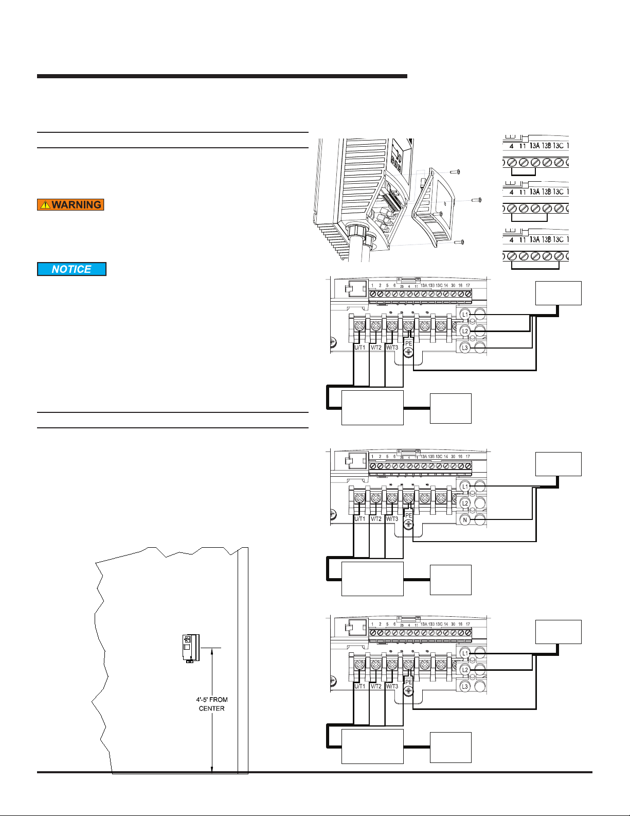
INSTALLATION,continued
Fig. 22
STANDARD UNITS
NOTE:
Reference wiring diagrams on pages 25-27 for all eld
connections.
INSTALL VFD
The VFD must be mounted approximately 53" above
the ground on the wall; use no more than 82 linear feet
(25m) of wire between VFD and fan motor.
Verify voltage and phase before mounting. Ensure
voltage shown on VFD box is correct.
2. Mount VFD approximately 53" above the oor on the
wall. See Fig. X. Cable will need to be extended. Use
junction box and extend using either SO or conduit and
appropriately rated wire.
3. Route the fan SO cable from the fan to the VFD box.
Ensure the cable is supported throughout its routing.
NOTE:
Factory S.O. cable is 20 ft long. Additional cable/conduit
provided by others.
4. Route supply power from the building source to the
VFD box.
5. Wire VFD box. See Fig. 22 and electrical schematics
located on pages 35-37.
Fig. 21
Red
White
Black
Junction
Box
(PROVIDED BY OTHERS)
To Fan
Motor
Incoming
Power
Red
White
Black
Green
Three phase wiring
Red
White
Black
Green
Junction
Box
(PROVIDED BY OTHERS)
To Fan
Motor
Incoming
Power
Black
White
Green
120VAC single phase wiring
Red
White
Black
Junction
Box
(PROVIDED BY OTHERS)
To Fan
Motor
Incoming
Power
Red
Black
Green
240VAC single phase wiring
Jumper settings for fan size
12'
16'
20'
GreenGreen

April 2019 6022110A — 3 Blade HVLS Fans 19
COMPONENTS AND SPECIFICATIONS
VFD – NEMA4X, Solid State VFD (Variable Frequency
Drive), 120VAC/1PH, 208-240VAC/1PH, 208-600VAC/3PH.
No line reactor. UL and UL-C listed panel. Power
disconnect. FUSED BY OTHERS.
MOTOR
NEMA standard T.E.F.C., 1 HP, continuous duty three
phase
GEARBOX
Double helical gear reduced, sealed lubrication.
VFD unit
Blade
Powerhead
Safety cable
Clamp
Universal mount
Guy wires
Fig. 23

20 6022110A — 3 Blade HVLS Fans April 2019
OPERATING INSTRUCTIONS,continued
Fig. 24
Stop
RunUp arrow
Down arrow
Enter
Reverse/Forward
VFD Touchpad
Before operating the industrial 3 Blade fan, read and
follow the Safety Practices, Warnings and Operating
Instructions in this manual. Use by untrained
personnel could result in death or serious injury.
VERIFY PRIOR TO OPERATION
1. Voltage/phase.
2. Obstruction clearance.
3. Safety cables present and properly installed.
4. All fasteners are properly torqued.
RUNNING THE FAN
1. Verify correct direction from the front display by visually
inspecting for the forward or reverse led lit on the
touchpad. See Fig. 24.
2. To change directions press the Reverse/Forward button
and then within 2 seconds press the enter button.
3. Using the up and down arrows select the desired speed
(1-5).
4. Press the green RUN button and the fan will begin
motion.
CHANGING DIRECTION DURING MOTION
1. To change direction while in motion press the Reverse/
Forward button then within 2 seconds press the enter
button.
2. It is not necessary to stop the fan prior to changing
directions.
CHANGING SPEED DURING MOTION
1.
Using the up and down arrows set the desired speed
(1-5).
2. The display will change automatically back to running
speed after 2 seconds.
3. To verify speed change the fan will slowly start to
increase/decrease speed indicated on the display.
STOPPING THE FAN
1. To stop the fan press the red stop button
2. The current speed will start decreasing to 0.0 where
the display will change to STOP
3. The set speed and direction at shutdown remains in
memory and upon a consecutive run signal will resume
last used speed and direction.
FAULT CODES
If a fault code alarm appears, select the Fault Codes
button to display the fault codes,.
To navigate back to the main screen, Select the green
return arrow.
The fault code screen will display the current fault code
number and gives a description of each fault code. If the
fan is currently under fault, the error code being displayed
in the box under the green arrow will be displaying a
number that caused the fault. Match the number with the
error codes and remove the fault condition. Once the
condition has been removed, pressing the reset button will
reset the fan and allow operation again. The Fault History
of the last 4 faults are displayed. Finally, the green arrow in
the upper right corner will navigate back to the diagnostic
screen. See Fig. 24.
Table of contents
Popular Fan manuals by other brands

Bionaire
Bionaire BASF1016G instruction manual

Home Decorators Collection
Home Decorators Collection MERWRY SW1422 Use and care guide

Inverter
Inverter iV14-MaxAir installation instructions

Sapir
Sapir SP-1760-DC6 instruction manual

Alf
Alf ISIV-01 user manual

BLAUBERG Ventilatoren
BLAUBERG Ventilatoren Iso-ZS user manual


