Epiroc YT29A Specifications

Secoroc YT29A, T29AE,
YT29AE(T), 7655D
pusher leg rock drills
Operator’s instructions
Spare parts list

2
Table of contents
Introduction �����������������������������������������������������������������3
Safety instructions ������������������������������������������������������3
Scope of application����������������������������������������������������8
Specification���������������������������������������������������������������������������������������� 8
Operation ���������������������������������������������������������������������9
Using the rock drill for the first time ������������������������������������������������� 9
Preparations before starting �������������������������������������������������������������� 9
Fitting and removing the tool ���������������������������������������������������������� 10
Before fitting the working tool��������������������������������������������������������� 10
Fitting the working tool �������������������������������������������������������������������� 10
Removing the working tool�������������������������������������������������������������� 10
Attaching the pusher leg to the rock drill���������������������������������������� 10
Controls ��������������������������������������������������������������������������������������������� 10
Throttle lever������������������������������������������������������������������������������������� 10
Feed control �������������������������������������������������������������������������������������� 10
Trigger ����������������������������������������������������������������������������������������������� 10
Oil regulating valve ���������������������������������������������������������������������������11
Drilling ������������������������������������������������������������������������������������������������11
Starting the rock drill �������������������������������������������������������������������������11
Stopping the rock drill�����������������������������������������������������������������������11
Re-positioning the pusher leg ����������������������������������������������������������11
Blow-cleaning the drill hole��������������������������������������������������������������11
When you have finished drilling ������������������������������������������������������11
Maintenance�������������������������������������������������������������������������������������� 12
Selection of spare parts�������������������������������������������������������������������� 12
Once a shift (after 8 hours of operation)����������������������������������������� 12
Once a week (after 40 hours of operation) ������������������������������������� 12
Once a month (after 200 hours of operation)��������������������������������� 12
Measures to prevent freezing ���������������������������������������������������������� 13
Scrapping and waste disposal��������������������������������������������������������� 13
CE Declaration of Conformity ���������������������������������������������������������� 14
Trouble shooting��������������������������������������������������������15
Spare parts list and exploded drawing �������������������16
Foreword
Thank you for selecting the SecorocYT29A,YT29AE,YT29AE(T) or
7655D pusher leg rock drill�
These instructions were developed to help you get the best per-
formance and productivity from the use of your new rock drill�
Please refer to them also for correct maintenance of the machine�

3
Introduction
Thank you for choosing a product from Epiroc� We have a strong
global sales and service network, consisting of customer centers
and distributors worldwide� Our experts are highly trained
professionals with extensive product knowledge and application
experience� In all corners of the world, we can offer product
support and expertise to ensure that our customers can work at
maximum efficiency at all times�
For more information please visit: epiroc�com
Epiroc Drilling Tools AB, Sweden�
About the Safety and operating instructions
The aim of the instructions is to provide you with knowledge
of how to use the rock drill in an efficient, safe way� The
instructions also give you advice and tell you how to perform
regular maintenance on the rock drill� Before using the rock drill
for the first time you must read these instructions carefully and
understand all of them�
Safety instructions
To reduce the risk of serious injury or death to yourself or
others, read and understand the Safety and operating instruction
before installing, operating, repairing, maintaining, or changing
accessories on the machine� Post this Safety and operating
instruction at work locations, provide copies to employees,
and make sure that everyone reads the Safety and operating
instruction before operating or servicing the machine� In
addition, the operator or the operator's employer must assess
the specific risks that may be present as a result of each use of
the machine�
Safety signal words
The safety signal words Danger, Warning and Caution have the
following meanings:
Indicates a hazardous situation which, if not avoided, will
result in death or serious injury�
DANGER
Indicates a hazardous situation which, if not avoided, could
result in death or serious injury�
WARNING
Indicates a hazardous situation which, if not avoided, could result
in minor or moderate injury�
CAUTION
Personal precautions and qualifications
Only qualified and trained persons may operate or maintain
the machine. They must be physically able to handle the
bulk, weight, and power of the tool. Always use your common
sense and good judgement.
Personal protective equipment
Always use approved protective equipment� Operators and all
other persons in the working area must wear protective equip-
ment, including at a minimum:
• Protective helmet
• Hearing protection
• Impact resistant eye protection with side protection
• Respiratory protection when appropriate
• Protective gloves
• Proper protective boots
• Appropriate work overall or similar clothing (not loose-fitting)
that covers your arms and legs�

4
Drugs, alcohol or medication
Drugs, alcohol or medication�
WARNING
Drugs, alcohol or medication may impair your judgment and pow-
ers of concentration� Poor reactions and incorrect assessments
can lead to severe accidents or death�
• Never use the machine when you are tired or under the influ-
ence of drugs, alcohol or medication�
• No person who is under the influence of drugs, alcohol or medi-
cation may operate the machine�
Installation, precaution
Whipping air hose�
DANGER
A compressed air hose that comes loose can lash around and
cause personal injury or death�To reduce this risk:
• Check that the compressed air hose and the connections are not
damaged, replace if necessary�
• Check that all compressed air connections are properly attached�
• Never carry a pneumatic machine by the air hose�
• Never attempt to disconnect a compressed air hose that is pres-
surized� First switch off the compressed air at the compressor and
then bleed the machine by activating the start and stop device�
• Do not use quick disconnect couplings at tool inlet�
Use hardened steel (or material with comparable shock resist-
ance) threaded hose fittings�
• Whenever universal twist couplings (claw couplings) are used,
we recommend that lock pins are installed and whipcheck safety
cables are used to safeguard against possible hose to tool and
hose to hose connection failure�
Ejected insertion tool�
WARNING
If the tool retainer on the machine is not in a locked position, the
inserted tool can be ejected with force, which can cause personal
injury�
• Never start the machine while changing the insertion tool�
• Before changing the insertion tool or accessories, stop the
machine, switch off the power supply and bleed the machine by
activating the start and stop device�
• Never point the inserted tool at yourself or anyone else�
• Make sure that the insertion tool is fully inserted and the tool
retainer is in a locked position before the machine is started�
• Check the locking function by pulling the inserted tool outwards
forcefully�
Moving or slipping insertion tool�
WARNING
An incorrect dimension of the inserted tool’s shank can result in
that the inserted tool is lost or is slipping out during operation�
Risk of severe injury or crushed hands and fingers�
• Check that the insertion tool has the shank length and dimen-
sions that the machine is intended for�
• Never use an insertion tool without a collar�
Operation, precautions
Explosion hazard�
DANGER
If a warm insertion tool comes into contact with explosives, an
explosion could occur� During operation with certain materials as
well as use of certain materials in machine parts, sparks and igni-
tion can occur� Explosions will lead to severe injuries or death�
• Never operate the machine in any explosive environment�
• Never use the machine near flammable materials, fumes or dust�
• Make sure that there are no undetected sources of gas or explo-
sives�
• Never drill in an old hole
Unexpected movements�
WARNING
The inserted tool is exposed to heavy strains when the machine
is used�The inserted tool may break due to fatigue after a certain
amount of use� If the inserted tool breaks or gets stuck, there may
be sudden and unexpected movement that can cause injuries�
Furthermore, losing your balance or slipping may cause injury�
• Make sure that you always keep a stable position with your feet
as far apart as your shoulder width, and keeping a balanced body
weight�
• Always inspect the equipment prior to use� Never use the equip-
ment if you suspect that it is damaged�
• Make sure that the handles are clean and free of grease and oil�
• Keep your feet away from the inserted tool�
• Stand firmly and always hold on to the machine with both
hands�
• Never drill in an old hole�
Unexpected movements�
WARNING
The inserted tool is exposed to heavy strains when the machine
is used�The inserted tool may break due to fatigue after a certain
amount of use� If the inserted tool breaks or gets stuck, there may

5
be sudden and unexpected movement that can cause injuries�
Furthermore, losing your balance or slipping may cause injury�
• Make sure that you always keep a stable position with your feet
as far apart as your shoulder width, and keeping a balanced body
weight�
• Always inspect the equipment prior to use� Never use the equip-
ment if you suspect that it is damaged�
• Make sure that the handles are clean and free of grease and oil�
• Keep your feet away from the inserted tool�
• Stand firmly and always hold on to the machine with both
hands�
• Never drill in an old hole�
• Never start the machine when it is lying on the ground�
• Never ‘ride’ on the machine with one leg over the handle�
• Never strike or abuse the equipment�
• Check regularly for wear on the insertion tool, and check whether
there are any signs of damage or visible cracks�
• Pay attention and look at what you are doing
Stalling hazard�
WARNING
If the insertion tool gets caught during operation, the whole
machine will start to rotate if you lose your grip on it�This unex-
pected rotation of the entire machine may cause serious injury or
death�
• Stand firmly and always hold onto the machine with both hands�
• Make sure that the handle or handles are clean and free from
grease and oil�
• Never drill in an old hole�
Trapping hazard�
WARNING
There is risk of neck ware, hair, gloves and clothes getting
dragged into or caught by a rotating insertion tool or accessories�
This may cause choking, scalping, lacerations or death�To reduce
the risk:
• Never grab or touch a rotating drill steel�
• Avoid wearing clothing, neck ware or gloves that may get
caught�
• Cover long hair with a hair net
Always make sure that the rock drilling tools are in good con-
dition before use�
CAUTION
Dust and fume hazard�
WARNING
Dusts and/or fumes generated or dispersed when using the
machine may cause serious and permanent respiratory disease,
illness, or other bodily injury (for example, silicosis or other irre-
versible lung disease that can be fatal, cancer, birth defects, and/
or skin inflammation)� Some dusts and fumes created by drilling,
breaking, hammering, sawing, grinding and other construction
activities contain substances known to the State of California
and other authorities to cause respiratory disease, cancer, birth
defects, or other reproductive harm� Some examples of such
substances are:
• Crystalline silica, cement, and other masonry products�
• Arsenic and chromium from chemically-treated rubber�
• Lead from lead-based paints�
Dust and fumes in the air can be invisible to the naked eye, so do
not rely on eye sight to determine if there is dust or fumes in the
air�To reduce the risk of exposure to dust and fumes, do all of the
following:
• Perform site-specific risk assessment�The risk assessment
should include dust and fumes created by the use of the machine
and the potential for disturbing existing dust�
• Use proper engineering controls to minimize the amount of
dust and fumes in the air and to minimize build-up on equipment,
surfaces, clothing, and body parts� Examples of controls include:
exhaust ventilation and dust collection systems, water sprays, and
wet drilling� Control dusts and fumes at the source where pos-
sible� Make sure that controls are properly installed, maintained
and correctly used�
• Wear, maintain and correctly use respiratory protection as in-
structed by your employer and as required by occupational health
and safety regulations�The respiratory protection must be effec-
tive for the type of substance at issue (and if applicable, approved
by relevant governmental authority)�
• Work in a well ventilated area�
• If the machine has an exhaust, direct the exhaust so as to reduce
disturbance of dust in a dust filled environment�
• Operate and maintain the machine as recommended in the oper-
ating and safety instructions
• Select, maintain and replace consumables/ inserted tools/ other
accessory as recommended in the operating and safety instruc-
tions� Incorrect selection or lack of maintenance of consumables/
inserted tools/ other accessories may cause an unnecessary
increase in dust or fumes�
• Wear washable or disposable protective clothes at the worksite,
and shower and change into clean clothes before leaving the
worksite to reduce exposure of dust and fumes to yourself, other
persons, cars, homes, and other areas�
• Avoid eating, drinking, and using tobacco products in areas
where there is dust or fumes�
• Wash your hands and face thoroughly as soon as possible upon
leaving the exposure area, and always before eating, drinking, us-
ing tobacco products, or making contact with other persons�
• Comply with all applicable laws and regulations, including oc-
cupational health and safety regulations�
• Participate in air monitoring, medical examination programs,
and health and safety training programs provided by your em-
ployer or trade organizations and in accordance with occupational
health and safety regulations and recommendations� Consult with
physicians experienced with relevant occupational medicine�

6
• Work with your employer and trade organization to reduce dust
and fume exposure at the worksite and to reduce the risks� Effec-
tive health and safety programs, policies and procedures for pro-
tecting workers and others against harmful exposure to dust and
fumes should be established and implemented based on advice
from health and safety experts� Consult with experts�
• Residues of hazardous substances on the machine can be a risk� Be-
fore undertaking any maintenance on the machine clean it thoroughly�
Projectiles�
WARNING
Failure of the work piece, of accessories, or even of the machine
itself may generate high velocity projectiles� During operating,
splinters or other particles from the working material may be-
come projectiles and cause personal injury by striking the opera-
tor or other persons�To reduce these risk:
• Use approved personal protective equipment and safety helmet,
including impact resistant eye protection with side protection�
• Make sure that no unauthorised persons trespass into the work-
ing zone�
• Keep the workplace free from foreign objects�
• Ensure that the work piece is securely fixed�
Splinters hazard�
WARNING
Using the insertion tool as a hand struck tool can result in splin-
ters hitting the operator and can cause personal injury�
• Never use an insertion tool as a hand struck tool� They are spe-
cifically designed and heat-treated to be used only in a machine�
Slipping, tripping and falling hazards�
WARNING
There is a risk of slipping or tripping or falling, for example trip-
ping on the hoses or on other objects� Slipping or tripping or
falling can cause injury�To reduce this risk:
• Always make sure that no hose or other object is in your way or
in any other person’s way�
• Always make sure you are in a stable position with your feet as
far apart as your shoulders width and keeping a balanced body
weight�
Motion hazards�
WARNING
When using the machine to perform work-related activities, you
may experience discomfort in the hands, arms, shoulders, neck,
or other parts of the body�
• Adopt a comfortable posture whilst maintaining secure footing
and avoiding awkward off-balanced postures�
• Changing posture during extended tasks may help avoid dis-
comfort and fatigue�
• In case of persistent or recurring symptoms, consult a qualified
health professional�
Vibration hazards
WARNING
Normal and proper use of the machine exposes the operator to
vibration� Regular and frequent exposure to vibration may cause,
contribute to, or aggravate injury or disorders to the operator’s
fingers, hands, wrists, arms, shoulders and/or nerves and blood
supply or other body parts, including debilitating and/or perma-
nent injuries or disorders that may develop gradually over peri-
ods of weeks, months, or years� Such injuries or disorders may
include damage to the blood circulatory system, damage to the
nervous system, damage to joints, and possibly damage to other
body structures� If numbness, persistent recurring discomfort,
burning sensation, stiffness, throbbing, tingling, pain, clumsiness,
weakened grip, whitening of the skin, or other symptoms occur at
any time, when operating the machine or when not operating the
machine, stop operating the machine, tell your employer and seek
medical attention� Continued use of the machine after the occur-
rence of any such symptom may increase the risk of symptoms
becoming more severe and/or permanent� Operate and maintain
the machine as recommended in these instructions, to prevent
an unnecessary increase in vibration�The following may help to
reduce exposure to vibration for the operator:
• Let the tool do the job� Use a minimum hand grip consistent
with proper control and safe operation�
• If the machine has vibration absorbing handles, keep them in a
central position, avoid pressing the handles into the end stops�
• When the percussion mechanism is activated, the only body
contact with the machine you should have are your hands on the
handle or handles� Avoid any other contact, for example support-
ing any part of the body against the machine or leaning onto the
machine trying to increase the feed force� It is also important not
to keep the start and stop device engaged while extracting the
tool from the broken work surface�
• Make sure that the inserted tool is well-maintained (including
sharpness, if a cutting tool), not worn out, and of the proper size�
Insertion tools that are not well-maintained, or that are worn out,
or that are not of the proper size result in longer time to complete
a task (and a longer period of exposure to vibration) and may
result in or contribute to higher levels of vibration exposure�
• Immediately stop working if the machine suddenly starts to
vibrate strongly� Before resuming the work, find and remove the
cause of the increased vibrations�
• Never grab, hold or touch the inserted tool when using the
machine�
• Participate in health surveillance or monitoring, medical exams
and training programs offered by your employer and when re-
quired by law�
• When working in cold conditions wear warm clothing and keep
hands warm and dry�
•The exhaust air is strongly chilled and shall not make contact
with the operator� Always direct the exhaust air away from hands
and body�
See the ”Noise and vibration declaration statement” for the
machine, including the declared vibration values�This information
can be found at the end of these Safety and operating instruc-
tions�
See the ”Noise and vibration declaration statement” for the
machine, including the declared vibration values�This information
can be found at the end of these Safety and operating instruc-
tions�

7
• Comply with the recommended air-pressure when operating the
machine� Either higher or lower air-pressure has the potential of
resulting in higher levels of vibration�
Electrical hazard�
DANGER
The machine is not electrically insulated� If the machine comes
into contact with electricity, serious injuries or death may result�
• Never operate the machine near any electric wire or other source
of electricity�
• Make sure that there are no concealed wires or other sources of
electricity in the working area�
Concealed object hazard�
WARNING
During operating, concealed wires and pipes constitute a danger
that can result in serious injury�
• Check the composition of the material before operating�
• Watch out for concealed cables and pipes for example electricity,
telephone, water, gas and sewage lines etc�
• If the inserted tool seems to have hit a concealed object, switch
off the machine immediately�
• Make sure that there is no danger before continuing�
Involuntary start�
WARNING
Involuntary start of the machine may cause injury�
• Keep your hands away from the start and stop device until you
are ready to start the machine�
• Learn how the machine is switched off in the event of an emer-
gency�
• Release the start and stop device immediately in all cases of
power supply interruption�
• Whenever fitting or removing the insertion tool, switch off the air
supply, bleed the machine by pressing the start and stop device
and disconnect the machine from the power source�
Noise hazard�
WARNING
High noise levels can cause permanent and disabling hearing loss
and other problems such as tinnitus (ringing, buzzing, whistling,
or humming in the ears)�To reduce risks and prevent an unneces-
sary increase in noise levels:
• Risk assessment of these hazards and implementation of appro-
priate controls is essential�
• Operate and maintain the machine as recommended in these
instructions�
• Select, maintain and replace the working tool as recommended
in these instructions�
• If the machine has a silencer, check that it is in place and in good
working condition�
• Always use hearing protection�
• Use damping material to prevent work pieces from ‘ringing’�
Maintenance, precautions
Machine modification�
WARNING
Any machine modification may result in bodily injuries to yourself
or others�
• Never modify the machine� Modified machines are not covered
by warranty or product liability�
• Always use original parts, working tools and accessories ap-
proved by Epiroc�
• Change damaged parts immediately�
• Replace worn components in good time�
Hot insertion tool�
CAUTION
The tip of the insertion tool can become hot and sharp when
used�Touching it can lead to burns and cuts�
• Never touch a hot or sharp insertion tool�
• Wait until the insertion tool has cooled down before carrying out
maintenance work�
Working tool hazards�
WARNING
Accidental engagement of the start and stop device during main-
tenance or installation can cause serious injuries, when the power
source is connected�
• Never inspect, clean, install, or remove the working tool while
the power source is connected�
Storage, precautions
• Keep the machine and tools in a safe place, out of the reach of
children and locked up�
The machine should not be used in environment where there
is a risk of explosions� Local regulations must be followed�The
machine is not certificated according to ATEX requirements�
CAUTION

8
Scope of
application
SecorocYT29A,YT29AE,YT29AE(T)and 7655D is a heavy-duty
pusher leg Rock Drill featuring high efficiency and low air con-
sumption� It is primarily designed for drilling in mines, hydro-
power stations, and road construction projects� It is also a new
product suitable for tunneling and other stone works in mining
and metallurgical industry�
SecorocYT29A is suitable for both horizontal and upward anchor
holes in medium-hard and hard rocks (100–350 MPa)�The hole
diameter range is from 32 mm to 45 mm with depths up to 5
meters�The Rock Drill is equipped with lubricator FY250� Secoroc
YT29A is intended to be used together with pusher leg FT160A,
FT160B, FT160C for different tunneling and work conditions� It is
also designed for dry drilling or wet drilling mounted on rigs�
Specification
Pneumatic
rock drill
YT29A,
YT29AE
YT29AE
(T)
7655D
Weight 27 32 24 Kg
Dimension
(L x W xH) 659x248x205 807x450x255 668x232x202 mm
Cylinder
Diameter 82 82 70 mm
Piston
Stroke 60 60 70 mm
Working
Pressure 4-6,3 4-6,3 4-6,3 Bar
Impact
Energy (at
5 bar (e))
≥70 ≥70 ≥57 J
Air
Consump-
tion (at 5
bar (e))
≤65 ≤65 ≤52 l/s
Impact
Frequency
(at 5 bar (e))
≥37 ≥37 ≥31 Hz
Water
Pressure
Working
Pressure -1
Working
Pressure -1
Working
Pressure -1 Bar
Air Hose
Inner
Diameter
25 25 19 mm
Water
Hose Inner
Diameter
13 13 13 mm
Drilling
Diameter 32-45 32-45 34-42 mm
Max
Drilling
Depth
5 5 5 m
Working
Temp-
erature
-30 to + 45 -30 to + 45 -30 to + 50 ºC
Shank
Size H22/25x108 H22/25x108 H22x108 mm
Lubricator
FY250
Lubricator
FY250
Lubricator
FY200
Weight 1�2 1�2 1,2 Kg
Capacity 0�25 0�25 0,2 litre
Safety instructions
To reduce the risk of serious injury or death to yourself or others,
carefully read through this instruction booklet before putting
the rock drill to use� Always follow the instructions given in this
manual�
• Always wear a safety helmet, goggles and ear protectors during
drilling� Any local regulations that exist must also be observed�
• When drilling in certain minerals, there is a risk of spark genera-
tion� Before starting work, check that the machine is approved (in
accordance with local regulations) for work under such condi-
tions�
• Always take great care when using the machine�The working
tool is subjected to heavy loading and can break, with a risk of
injury to personnel�
• Check that the hoses used are of the right quality, and that all
hose connections are in good condition and properly tightened�
• Before starting work on any of the systems, make sure that the
air and water systems are without pressure�
• Make sure that there are no concealed wires or other sources of
electricity� Never drill near any electric wires or other sources of
electricity�
• Always make sure that main valve on the main hose is switched
off when the rock drill is not in use� This is needed to avoid the risk
of unintentional start of the machine�
• During drilling, stand firmly and always hold the machine with
both hands� Do not hang or lean over the machine during opera-
tion, as there is a risk of injuries due to falling� Always use PPE
(Personal Protective Equipment) when operating the rock drill�
Overview
To reduce the risk of serious injury or death to yourself or others,
read the Safety instructions section found on the previous pages
of this manual before operating the machine�
Labels
The machine is fitted with labels containing important information
about personal safety and machine maintenance�The labels must
be in such condition that they are easy to read� New labels can be
ordered from the spare parts list�
Data plate
A� Machine type
B� Maximum permitted compressed air pressure
C� Serial number
D�The warning symbol together with the book symbol means that
the user must read the safety and operating instructions before
the machine is used for the first time�
E�The CE symbol means that the machine is EC-approved� See the
EC declaration which is delivered with the machine for more infor-
mation� If the CE symbol is missing, it means that the machine is
not EC-approved�

9
Lubricant recommendation
Use a mineral-based air tool oil
Ambient temperature ºC Viscosity grade (ISO 3448)
-30 to 0 ISO VG 32-68
-10 to +20 ISO VG 68-100
+10 to +50 ISO VG 100-150
4� Air/water pressure and hose dimensions
Air pressure
Ensure that the compressor can deliver the required air pressure
of 5 bar at the machine�
• High pressure (>6�3 bar) causes rough operation and damage�
• Low pressure (<4 bar) results in a slow drilling speed�
Water pressure
Make sure that the water pressure is set to around 3 bar�
Note! Maximum water pressure is 1 bar less than the working
pressure� For example if the air pressure is 5 bar, the water pres-
sure must be below 4 bar to prevent water entering the impact
mechanism�
Note! Dry drilling is strictly prohibited� Operation without air- and
water tubes is not allowed as it will result in poor drilling perfor-
mance�
Hose dimensions
The air hose diameter must be no less than 25mm� Inner diameter
of connection nipple and hose must be no less than 19mm�The
ideal overall air hose length is less than 15m�
Drill steel
Ejected insertion tool�
WARNING
If the tool retainer on the machine is not in a locked position, the
inserted tool can be ejected with force, which can cause personal
injury�
• Before changing the insertion tool, stop the machine, switch off
the compressed air supply and bleed the machine by activating
the start and stop device�
Before fitting the insertion tool
Check that the tool shank is of the correct size and length for the
chuck used�The shank must be clean and the tool must be in good
condition� Shanks which are chipped, rounded, out of square or
too hard on the striking end will operate inefficiently and cause
premature piston failure� Inspect the drill steel:
A dull drill steel will slow down the drilling speed and overstrain
the drill mechanism� When changing drill steel make sure that
the new one is the correct size to follow your previous bore�
Before drilling, check that the flushing hole in the drill steel is not
blocked�
Safety label
A
B
C
DE
To avoid injury, before using or servicing tool, read and under-
stand separately provided safety instructions�
Operation
Using the rock drill for the first time
When the rock drill arrives from the factory, the inside of the tool
is coated with heavy oil to prevent corrosion�
After unpacking and installing the tool, pour a small amount of lu-
brication oil into the air connection and operate the tool on partial
throttle to clean the interior� Follow this immediately with a liberal
amount of air tool oil�
The rock drill and pusher leg are lubricated with oil mixed with
compressed air, which is taken to the parts that need continu-
ous lubrication� Oil is metered into the compressed air using the
FY250 lubricator connected to the air line�
Preparations before starting
1� Check the drilling equipment
• Check that all of the drilling equipment is in good working order�
• Check that the impact surface of the drill steel shank is flat with
no signs of wear�
• Make sure that the air inlet and exhaust ports are free from
obstructions�
• Check that the flushing holes in the drill steel and drill bit are
not blocked and that the flushing air/water flows through without
obstruction�
• Ensure that the fittings are tight and leak-proof�
Always check for damaged or loose hoses and fittings before
operation�Whipping hoses can cause serious injury�
WARNING
2� Blow out the air hose
Every day before using the drill, blow out the air hose to clear it
from accumulated dirt and moisture�
3� Fill the lubricator with oil
• Fill the lubricator (located on top of the cylinder) with oil if nec-
essary�The rock drill is lubricated with oil mixed with compressed
air, which is taken to the parts that need continuous lubrication�
Oil is metered into the compressed air�
• Use Atlas Copco Rock Drill AIR-OIL as a lubricant�

10
Hot insertion tool�
CAUTION
The tip of the insertion tool can become hot and sharp when
used�Touching it can lead to burns and cuts�
• Never touch a hot or sharp insertion tool�
• Wait until the insertion tool has cooled down before carrying out
maintenance work�
Note: Never cool a hot insertion tool in water, it can result in brit-
tleness and early failure�
Fitting the drill steel
Whenever fitting the drill steel the following instructions must be
observed:
Fitting and removing the tool
Before fitting the working tool
• Check that the tool shank is of the correct size and length for the
chuck used�
•The shank must be clean and the tool must be in good condition�
•The suitable quenching hardness of the shank is HRC48-53�
Harder end face will cause piston damaged and breakage of the
end face of the piston� If the shank face is too soft, it will be easily
deformed by the piston, which will result in difficulty in removing
the working tool�
• Shank end face shall be flat and perpendicular to the axis�
• Remove sharp edges from the shank's end face� Rough shank
surface will cause premature piston failure�
• Inspect the bits: Dull bits will slow down the drilling speed and
overstrain the drill mechanism� When changing bits make sure
that the new bit is the correct size to follow your previous bore�
• Before drilling check that the flushing hole in the working tool is
not blocked�
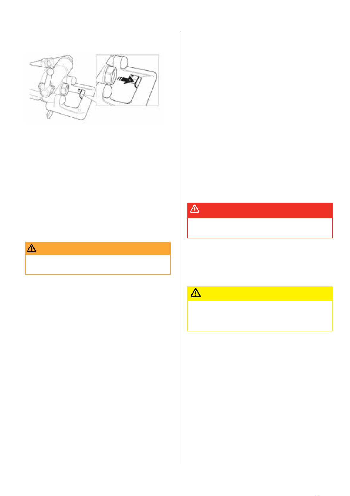
Fitting the working tool
1� Push the retainer outwards in the direction of the arrow (see
picture below), until the front portion of the retainer is able to ac-
commodate the working tool collar�
2� Insert the drill in the chuck�
3� When the drill bottoms, push back the retainer to lock it�
Removing the working tool
1� Push the retainer outwards in the direction of the arrow until the
working tool collar disengages from the front of the retainer�
2� Pull the working tool out�
3� Push back the retainer�
Attaching the pusher leg to the rock drill
• Mount the pusher leg (1), lock sleeve (2), rubber pad (3), washer
(4) and locking nut (5) in the order shown in the picture below�
•Turn the locking nut clockwise with a wrench until you hear a
"click"�
Controls
Throttle lever
The rock drill is equipped with a throttle lever for regulating both
the compressed air to the percussion mechanism and the flushing
water�
A� Extra blowing, water flushing off, impact and rotation off�
B� Stop position, air and water off
C� Low throttle, air to pusher leg, water flushing
D� Medium throttle
E� Full throttle
Feed control
Adjust the feed force by means of the feed control lever as fol-
lows:
A� Extra blowing, water flushing off, impact and rotation off�
B� Stop position, air and water off
Trigger
When the trigger (A) is pushed in, the feed force stops abruptly
and the setting on the feed control lever is overridden�The piston
rod in the pusher leg retracts automatically�This function is used
for example to adjust the height of the rock drill, when rigging up
11
the pusher leg, or when there is a tendency to jam� When the trig-
ger is released, the feed control setting is activated again�
Oil regulating valve
Oil dosing is controlled by means of a screwdriver�
Check that sufficient lubrication is obtained by putting your hand
in front of the exhaust port while adjusting the regulating valve�
If the hand is covered by a thin film of oil after a few seconds, the
lubricator has been correctly adjusted�
The amount of oil going into the rock drill increases when turning
the valve counter clockwise, and it decreases when turning the
valve clockwise� Oil consumption is 2�5–6 ml/minute�
Note!Tighten the nut after regulation�
Note!To much oil will have negative effects on the operation
whilst to little will result in damage to parts as the temperature
rises during operation�
Operation
Involuntary start�
WARNING
Involuntary start of the machine may cause injury�
• Keep your hands away from the start and stop device until you
are ready to start the machine�
• Learn how the machine is switched off in the event of an emer-
gency�
• Stop the machine immediately in all cases of power supply
interruption�
Drilling
Starting the rock drill
1� Open the main valve for compressed air�
2� Open the cock for the flushing water�
3� Adjust the feed control lever to give a suitable feed force for
collaring the hole�
4� Align the rock drill so that the working tool touches the desired
collaring point�
5� Move the throttle lever forward a little, which will start water
flushing, percussion and rotation�
6� Collar the hole with reduced feed force�
7� Move the throttle lever fully forward once the working tool has
gained a secure footing in the rock�
Adjust the feed force by means of the control lever so that the 8�
maximum penetration rate is obtained�
The start-and-stop device of Pusher Leg Rock Drill YT29A can
cause a risk of an unimtentional start�To reduce and avoid causing
the risk of unintentional start, the control valve og inlet hose must
be switched off while the rock drill is put aside for long time�
Note! Do not bend the working tool as this will increase wear of
the shank bushing and piston� Furthermore, it can also affect drill-
ing efficiency and increase the risk of working tool breakage�
Stopping the rock drill
Pull the throttle lever backwards, which will stop percussion, rota-
tion and flushing water�
Re-positioning the pusher leg
1� Switch off the rock-drill percussion and flushing by means of
the throttle lever�
2� Press the trigger, whereupon the piston rod is pulled back into
the pusher-leg cylinder automatically�
3� Re-position the pusher leg�
4� Release the trigger, whereupon the piston rod will move out-
wards again�
5� Move the throttle lever forward into the working position�
Note!The feed control lever does not need to be touched through-
out this operation�
Blow-cleaning the drill hole
Whipping air hose�
DANGER
A compressed air hose that comes loose can lasharound and
cause personal injury or death
• Check that the compressed air hose and the connections are not
damaged�
• Check that all compressed air connections are properly attached�
Move to the side and cover your eyes before starting to blow-
clean the drill hole� When blow-cleaning, particles and dirty
flushing water can emerge at speed from the drill hole��
CAUTION
• Always wear impact resistant eye protection with side protection
to avoid injury�
• Make sure that no co-workers are in range when blow-cleaning�
If powerful blow-cleaning of the drill hole is required, turn the
throttle lever fully backwards beyond the stop position for extra
blowing, whereupon the rock drill stops�This can be done during
drilling� When the drill hole is clean, turn the throttle lever for-
wards again to re-start the rock drill�
When you have finished drilling
Run the rock drill at medium speed when retracting the working
tool from the drilled hole�
Lay down the rock drill on a stone, wooden plank or similar ob-
ject, so as to prevent drill cuttings and other foreign matter from
entering the chuck�
Turn off the water pressure before the air pressure� Run the rock
drill for a few seconds to clean out water and moisture after the
water has been shut off�

12
Always switch off the main control valve on the air inlet hose to
prevent unintentional start of the rock drill�
Maintenance
Regular maintenance is a prerequisite for machine safety� Replace
damaged and worn components in good time� For a major service
to the machine, contact your nearest authorized workshop�
Check the machine and tools for wear and damage at regular
intervals� Do not use very worn or damaged tools�
When cleaning mechanical parts with a solvent, make sure that
you comply with current health and safety regulations and ensure
that there is sufficient ventilation�
Daily maintenance, regular checking of wearing parts and carrying
out repairs in good time prevents breakdowns and increases the
service life of the machine�
• Always oil the rock drill and pusher leg well, before you put
them into storage�
• Store in a clean and dry place�
• Make sure that no foreign matter enters the machine�
• Protect the chuck using a wooden plug or a clean piece of cotton
waste�
• Always hose down and wipe clean the rock drill and pusher leg
after use�
• In the case of long-term storage, pour a quantity of oil directly
into the rock-drill's air intake and then turn on the air briefly�This
will protect the machine from corrosion�
Once a shift (after 8 hours of operation)
• Check the wear in the chuck bushing� If the wear limit has been
exceeded, the working tool shank will wear more quickly, or
become deformed�This will lead to stoppages and increased
working tool consumption�
• Check the tightness of the side-bolt nuts�
•The tightening torque shall be 150 Nm�
• Check the rock drill's connection to the pusher leg�
• Check the hoses, couplings and controls for leakage and dam-
age�
• Check that the rock drill and pusher leg are receiving enough
lubrication� Fill the lubricator as necessary�
• Drain the water separator�
• Check the air and water pressure� Make sure that the water pres-
sure is at least 1 bar lower than the air pressure�
Once a week (after 40 hours of operation)
Carry out a basic check of all functions of the drilling equipment�
Once a month (after 200 hours of operation)
• Send the rock drill to a workshop for inspection� The local operat-
ing conditions will determine whether or not this is a suitable
interval for overhauling the drill�
• Dismantle and clean the lubricator�
• Clean out the water separator�
Differences between original parts and
pattern parts
When buying a part, the first thing to do is to verify that the part is
an Atlas Copco part� Most parts can be identified�
Every day
Before undertaking any maintenance or changing the insertion
tool on pneumatic machines, always switch off the air supply and
bleed the machine by depressing the start and stop device then
disconnect the air hose from the machine�
• Clean and inspect the machine and its functions each day before
the work commences�
• Conduct a general inspection for leaks and damage�
• Check that the air inlet nipple is tightened and that the claw
coupling is free from damage�
• Check the function of the throttle handle� Make sure that it
moves freely up and down�
• Check the function of the retainer� Make sure that it locks the drill
steel�
• Change damaged parts immediately�
• Replace worn components in good time�
• Check the through bolts of the machine� Make sure that they are
tightened�
• If the machine is equipped with a silencer, check for damage�
Checking for wear
1� Check the wear in the chuck
bushing using the Atlas Copco
gauge 90002668 (22 mm),
90002669 (25 mm)� If the wear
limit has been exceeded, the drill
steel shank will wear more quickly,
or become deformed�This will
lead to stoppages and increased
drill-steel consumption�
2� Check the tightness of the side-
bolt nuts (A)�Tighten to a torque
of 80 Nm�
3� Check the rock drill's connection
to the pusher leg�
4� Check the hoses, couplings and controls for leakage and dam-
age�
5� Check that the rock drill and pusher leg are receiving enough
lubrication� Fill the lubricator if necessary�
6� Check the air and water pressure� Make sure that the water
pressure is at least 1 bar lower than the air pressure�
Periodic maintenance
After each operating period of approximately 100 working hours
or three times a year the machine must be dismantled and all
parts be cleaned and checked�This work must be performed by
authorized staff, trained for this task�
Selection of spare parts
This machine is a heavy-duty rock drill; there are strict require-
ments on selecting spare parts� Use only genuine parts for
replacement, to ensure stable performance� Do not use pattern
parts, which not only have a short working life but also cause con-
sequential damage to other parts, due to differing measurements
and methods of manufacturing�
Damage patterns
Worn or broken parts must always be studied carefully before
they are replaced�They can give important information about the
condition of the drill and about the way it is used and maintained�

13
Problem Cause
Steel parts are a bluish colour The parts have been
subjected to excessive
heat� This can be caused by
insufficient lubrication or
idling
Steel parts have small almost
microscopic fissures on the
wear surfaces
See above
Irregular cavities on the
surface See above of bronze
parts
See above
Cutting marks Secondary damage
Dirt inside the drill
Interior misalignment due to
uneven tension of the side
bolts
Measures to prevent freezing
In low ambient temperatures, ice can form in the machine�This
can be avoided if the water in the compressed air is removed�This
can be done by equipping the air lines with water separators and
drainage points for water condensate�
If the rock drill ices up, it must not be heated to melt the ice� Let
the ice thaw at room temperature�
Note! Do not pour methylated spirits or similar substances into
the rock drill, as they will interfere with the lubrication and lead to
increased wear�
Scrapping and waste disposal
Used and worn-out machines must be disposed of in such a way
that as much of the material as possible can be recycled and the
impact on the environment is kept to a minimum�
Noise and vibration declaration statement
Noise level is meassured according to ISO15744:2002� Vibration
in handle is meassured according to ISO28927-10:2011� See table
"Noise and vibration data" for the value�These declared values
were obtained by laboratory type testing in accordance with the
stated directive or standards and are suitable for comparison with
the declared values of other tools tested in accordance with the
same directive or standards�These declared values are not suit-
able for use in risk assessments and values measured in individu-
al work places may be higher�The actual exposure values and risk
of harm experienced by an individual user are unique and depend
upon the way the user works, in what material the machine is
used, as well as upon the exposure time and the physical condi-
tion of the user, and the condition of the machine� We, Epiroc
DrillingTools AB, cannot be held liable for the consequences of
using the declared values, instead of values reflecting the actual
exposure, in an individual risk assessment in a work place situa-
tion over which we have no control�This tool may cause hand-arm
vibration syndrome if its use is not adequately managed� An EU
guide to managing hand-arm vibration can be found at http://
www�humanvibration�com/humanvibration/EU/VIBGUIDE�html
We recommend a programme of health surveillance to detect
early symptoms which may relate to vibration exposure, so that
management procedures can be modified to help prevent future
impairment�
Technical data
Parameter/
Model YT29A YT29AE YT29AE
(T) 7655D
Product nr 96000010 96000896 96001048 96000004
Product
code
9605-0-
3312300312
9605-0-
3312300340
9605-0-
3312300342
9601-0-
3312300301
Weight
(Kg) 27 27 32 24
Shank size
(mm)
Hex
22 / 25
Hex
22 / 25
Hex
22 / 25
Hex
22
Piston
stroke
(mm)
60 60 60 70
Impact
frequency
(Hz) at 5
bar
≥37 ≥37 ≥37 ≥31
Impact
energy (J) ≥70 ≥70 ≥70 ≥57
Air con-
sumption
(l/s)
≤65 ≤65 ≤65 ≤52
Noise and vibration data
Machine Noise Vibration
YT 29 A 107 dB(A) 7,3 m/s2
YT 29 AE 104 dB(A) 6,6 m/s2
YT29AE(T) 104 dB(A) 6�6m/s2
7655 D 107 dB(A) 5,7 m/s2
Pusher Legs
Parameter\
Model FT160A FT160B FT160C
Product
Number 96000038 96000039 96000040
Product Code 9616-0-
3312300608
9617-0-
3312300609
9619-0-
3312300610
Weight kg 17 16 18
Length
retracted
mm
1688 1488 1820
Length
extracted mm 3026 2586 3310
Feed length
mm 1338 1098 1490
Piston bore
mm 65 65 65

14
Pusher Legs
Parameter\
Model 215PL 215PLA 215PLB
Product
Number 96000991 96001037 96001038
Product Code 9620-0-
3312300630
9620-0-
3312300636
9620-0-
3312300637
Weight kg 18 20 17
Length
retracted
mm
1570 1910 1100
Length
extracted
mm
2570 3210 1700
Feed length
mm 1000 1300 600
Piston bore
mm 62 62 62
EC Declaration of Conformity
(EC Directive 2006/42/EC)
We, Epiroc DrillingTools AB,hereby declare that the machines
listed below conform to the provisions of EC Directive 2006/42/EC
(MachineryDirective), and the harmonised standards mentioned
below�
Rock Drills Part number Pmax (bar)
YT29A 96000010 6�3
YT29AE 96000896 6�3
7655D 96000004 6�3
YT29AE(T) 96001048 6,3
Following harmonised standards were applied:
• EN ISO 11148-5
Technical Documentation authorised representative:
Thomas Greijer,
Epiroc DrillingTools AB,
Box 521,
SE-737 25 Fagersta, Sweden
Vice president Design and Development:
Jonas Falkestrom,
Epiroc DrillingTools AB,
Box 521,
SE-737 25 Fagersta, Sweden

15
Trouble shooting
Problem Cause Solution
Decreased
penetration rate
Air leakage in hoses, couplings Change packings, and where required, change parts in
the throttle valve�
Shank sleeve Check the shank sleeve for excessive wear� Replace if
necessary�
Air leakage due to worn piston/cylinder Replace the piston and/or cylinder
Air leakage due to worn guide sleeve/pilot guide Change the worn part
Insufficient feed
force
Piston rod seal (in pusher leg) worn or deformed Change the seal
O-rings on pusher leg coupling worn or deformed Change the o-rings
Poor rotation Splines of the rifle nut worn Replace the rifle nut if the splines are worn
Splines of the rifle bar worn down Replace the rifle bar when needed
Splines on the piston worn down Replace the piston when needed
The toothing in the ratchet housing is worn out Replace the ratchet housing if the tooth housing is so
worn that the pawls have difficulty catching
The toothing in the ratchet wheel is worn out Replace the ratchet wheel if the toothing is so worn that
the pawls have difficulty catching
Chuck nut worn out Replace the chuck nut if the splines have been worn to
1/2 of the spline width
Pawls worn Replace all pawls, all pawl springs and all pawl pins�
Uneven running Piston has seized in the guide sleeve or the piston guide Replace the guide sleeve/piston guide� If required,
polish the piston� Check the piston for heat damage
such as blue colouring and/or fissures� If it is damaged
in this way, replace the piston as well�
Dirty or damaged main valve� Caused by impurities or
foreign matter entering the drill with the compressed air
Clean and polish the valve so that it seals against the
corresponding cylindrical and plane sealing surfaces� If
this is not possible because the defects are too serious,
the valve must be replaced�
Freezing� Caused by leakage in the flushing system or
by excess water in the compressed air or by excessive
water pressure
Check the flushing tubes and seals and the water
pressure� Drain water from the compressed air system�
If the problem continues, fit a water separator in the
airline system�
Uneven running
(continued)
The side bolts are unevenly or insufficiently tightened�
Can cause the various parts to lose their alignment,
resulting in the seizure of the movable parts� Abnormal
strains on the side bolt may result in fracture at the
threads
Check and repair any damage to the contact points and
tighten the bolts with the correct tightening torque
The drill gets hot Lack of oil Add oil and check that it runs through� It is not sufficient
that there is oil in the exhaust air� There must also be an
oil coating on the shank of the working tool�
Freezing High level of humidity in the compressed air Use water traps
Water pressure higher than the air pressure Lower the water pressure
Water pipe
breakage
Misalignment of the shank Change working tool or shank sleeve or both
Damaged flushing hole in the shank Change working tool
Chipping of the
piston tip
Misalignment of the shank Change the working tool or shank sleeve or both
Excessive wear of the piston tip Change piston
Spline breakage
Lack of lubrication Lower the water pressure if it is the same as or greater
than the air pressure
Increase lubrication or change oil
Dirt intrusion (specially when drilling upwards) Increase service intervals
Piston breakage
Lack of lubrication Lower the water pressure if it is the same as or greater
than the air pressure
Increase lubrication or change oil
Uneven tension in the side bolts Tighten the bolts correctly
Worn guide sleeve/piston guide (can be confirmed by
the cushion test)
Change the worn part
Side bolt breakage Uneven tension on the bolts Tighten the bolts correctly

16
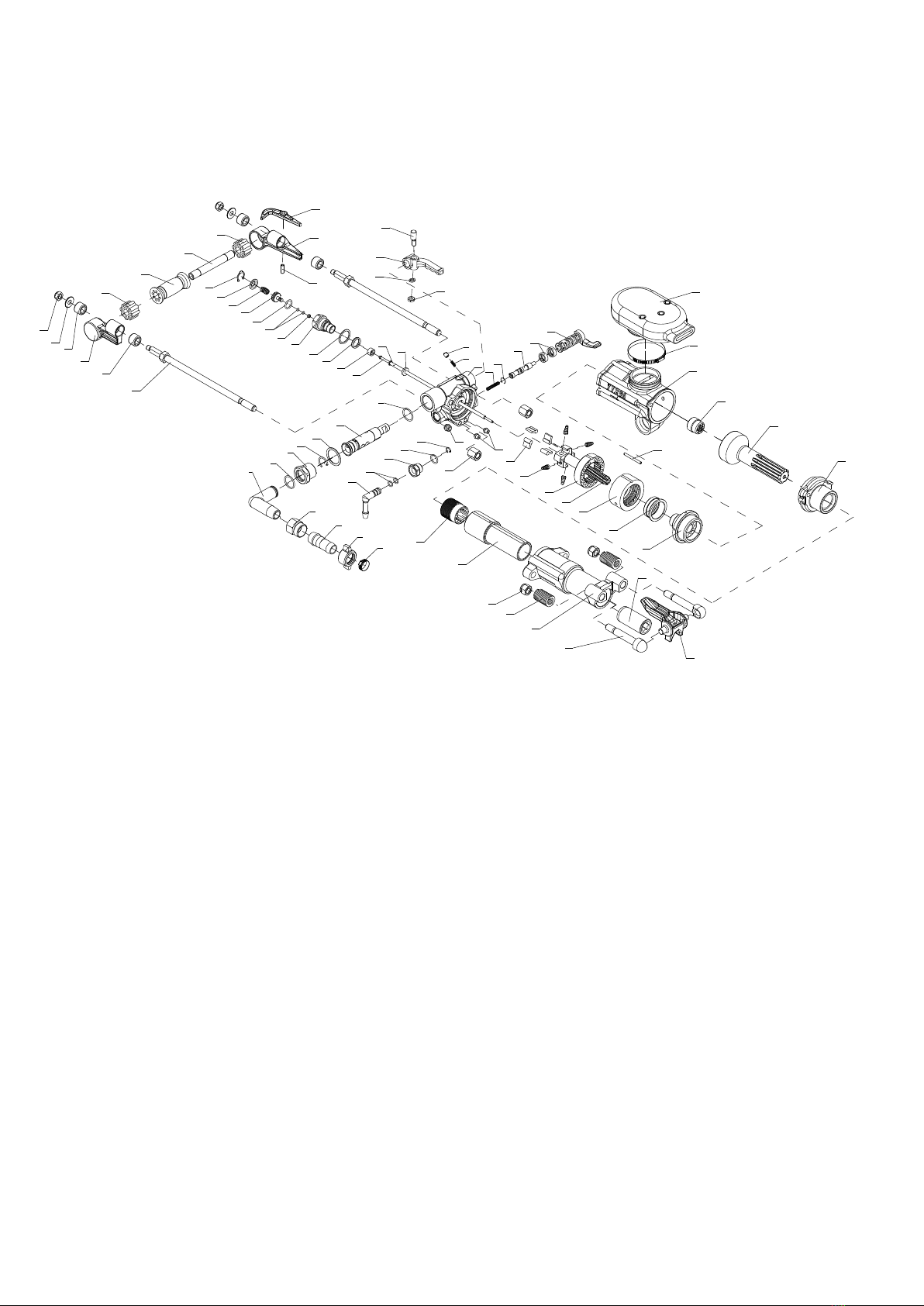
Spare parts list and exploded drawing YT29A

17
No� Description Quantity Product no� Product code
1 Spring 1 96000179 9605-1-3312310169
2 Pin 1 96000180 9605-1-3312310170
3Conical pipe
connector 1 96000186 9605-1-3312310176
4 Hoop 1 96000540 9605-1-3312310723
5 Wing nut 1 96000185 9605-1-3312310175
6Pipe
connector 1 96000187 9605-1-3312310177
7Air pipe
swivel 1 96000825 9600-1-3312310022
8 Air pipe nut 1 96000823 9600-1-3312310020
9 O-ring 2 96000486 9605-1-3312310633
10 Pad 1 96000174 9605-1-3312310164
11 Retaining
ring 1 96000182 9605-1-3312310172
12 Water pipe
connector 1 96000154 9603-1-3312310143
13 Water pipe
nut 1 96000155 9603-1-3312310144
14 O-ring 2 96000482 9605-1-3312310627
15 O-ring 2 96000499 9605-1-3312310667
16
Water pipe
connector
retaining
ring
1 96000156 9603-1-3312310145
17 Control
valve 1 96000646 9605-1-3312311868
18 Control
handle 1 96000152 9603-1-3312310141
19 Standard
spring pad 1 96000534 9605-1-3312310716
20 Hex� thin
nut 1 96000524 9605-1-3312310704
21 Fixing pin 1 96000177 9605-1-3312310167
22 Change
valve 1 96000161 9603-1-3312310150
23 Retaining
ring 1 96000160 9603-1-3312310149
24
Pressure
regulating
valve
1 96000119 9602-1-3312310101
25 Expansion 2 96000118 9602-1-3312310099
26 Spring 1 96000157 9603-1-3312310146
27 Conical
spring 4 96000167 9605-1-3312310156
28 Ratchet
pawl 4 96000166 9605-1-3312310155
29 Large seal
sleeve 1 96000544 9605-1-3312310727
30 Seal sleeve 2 96000543 9605-1-3312310726
31 Right
handle 1 96000163 9603-1-3312310152
32 Left handle 1 96000165 9603-1-3312310154
33 Shockproof
handle 1 96000164 9603-1-3312310153
No� Description Quantity Product no� Product code
34 Trigger 1 96000162 9603-1-3312310151
35 Elastic pin 1 96000527 9605-1-3312310708
36 Spring
cover 1 96000169 9605-1-3312310159
37
Steel
retaining
ring
1 96000183 9605-1-3312310173
38 Spring 1 96000170 9605-1-3312310160
39 Rotation nut 1 96000146 9603-1-3312310135
40 Pad 1 96000184 9605-1-3312310174
41 Water valve
body 1 96000171 9605-1-3312310161
42 Water valve 1 96000173 9605-1-3312310163
43 O-ring 2 96000489 9605-1-3312310642
44 Seal 1 96000181 9605-1-3312310171
45 Rubber pad 1 96000175 9605-1-3312310165
46 Back head 1 96000091 9605-1-3312310050
47 Water tube
bush 1 96000835 9601-1-3312310035
48 Air tube pad 1 96000176 9605-1-3312310166
49 Ratchet 1 96000092 9605-1-3312310051
50 Dowel pin 1 96000839 9601-1-3312310039
51 Valve chest 1 96000093 9605-1-3312310052
52 Valve 1 96000094 9605-1-3312310053
53 Valve sleeve 1 96000639 9605-1-3312311860
54 Rifle bar 1 96000640 9605-1-3312311861
55 Rifle nut 1 96000095 9605-1-3312310056
56 Exhaust
deflector 1 96000562 9605-1-3312311050
57 Hoop 1 96000542 9605-1-3312310725
58 Cylinder 1 96000641 9605-1-3312311862
59 Guide
sleeve set 1 96000096 9605-1-3312310059
60 Piston 1 96000642 9605-1-3312311863
61 Hex� Thick
nut 2 96000518 9605-1-3312310697
62 Side bolt 2 96000643 9605-1-3312311864
63 Air tube 1 96000644 9605-1-3312311865
64 Water tube 1 96000645 9605-1-3312311866
65 Front head 1 96000647 9605-1-3312311875
66 Rotation
sleeve 1 96000648 9605-1-3312311876
67
Nonmetal
hex�
Locking nut
2 96000531 9605-1-3312310713
68
Steel
retainer
springs
2 96000818 9600-1-3312310013
69
Steel
retainer
bolt
2 96000634 9600-1-3312311820
70 Shank
sleeve 1 96000168 9605-1-3312310157
71 Working
tool retainer 1 96000635 9600-1-3312311821
18
Spare parts list and exploded drawing YT29AE
72
73
74
31
74
62
4
5
3
6
7
9
8
11
10
17
9
12
15
13
14
16
1
2
46
26
23
22
25
24
48
63
64
47
44
40
41
45
43
14
42
38
36
37
34
32
35
21
18
19
20 56
57
58
55
60
59
61
30
29
28
27
49
54
51
50
52
53
39
66
67
68
65
70
69
71
75
33
76
75

19
No� Description Quantity Product no� Product code
1 Spring 1 96000179 9605-1-3312310169
2 Pin 1 96000180 9605-1-3312310170
3Conical pipe
connector 1 96000186 9605-1-3312310176
4 Hoop 1 96000540 9605-1-3312310723
5 Wing nut 1 96000185 9605-1-3312310175
6Pipe
connector 1 96000187 9605-1-3312310177
7Air pipe
swivel 1 96000825 9600-1-3312310022
8 Air pipe nut 1 96000823 9600-1-3312310020
9 O-ring 2 96000486 9605-1-3312310633
10 Pad 1 96000174 9605-1-3312310164
11 Retaining
ring 1 96000182 9605-1-3312310172
12 Water pipe
connector 1 96000154 9603-1-3312310143
13 Water pipe
nut 1 96000155 9603-1-3312310144
14 O-ring 2 96000482 9605-1-3312310627
15 O-ring 2 96000499 9605-1-3312310667
16
Water pipe
connector
retaining ring
1 96000156 9603-1-3312310145
17 Control valve 1 96000646 9605-1-3312311868
18 Control
handle 1 96000152 9603-1-3312310141
19 Standard
spring pad 1 96000534 9605-1-3312310716
20 Hex� thin nut 1 96000524 9605-1-3312310704
21 Fixing pin 1 96000177 9605-1-3312310167
22 Change
valve 1 96000161 9603-1-3312310150
23 Retaining
ring 1 96000160 9603-1-3312310149
24
Pressure
regulating
valve
1 96000119 9602-1-3312310101
25 Expansion 2 96000118 9602-1-3312310099
26 Spring 1 96000157 9603-1-3312310146
27 Conical
spring 4 96000167 9605-1-3312310156
28 Ratchet pawl 4 96000166 9605-1-3312310155
29 Large seal
sleeve 1 96000544 9605-1-3312310727
30 Seal sleeve 2 96000543 9605-1-3312310726
31 Right handle 1 96000887 9602-1-3312380076
32 Left handle 1 96000886 9602-1-3312380077
33
Anti-
vibration
handle
1 96000890 9602-1-3312380074
34 Trigger 1 96000162 9603-1-3312310151
35 Elastic pin 1 96000527 9605-1-3312310708
36 Spring cover 1 96000169 9605-1-3312310159
37
Steel
retaining
ring
1 96000183 9605-1-3312310173
38 Spring 1 96000170 9605-1-3312310160
39 Rotation nut 1 96000146 9603-1-3312310135
No� Description Quantity Product no� Product code
40 Pad 1 96000184 9605-1-3312310174
41 Water valve
body 1 96000171 9605-1-3312310161
42 Water valve 1 96000173 9605-1-3312310163
43 O-ring 2 96000489 9605-1-3312310642
44 Seal 1 96000181 9605-1-3312310171
45 Rubber pad 1 96000175 9605-1-3312310165
46 Back head 1 96000903 9605-1-3312380175
47 Water tube
bush 1 96000835 9601-1-3312310035
48 Air tube pad 1 96000176 9605-1-3312310166
49 Ratchet 1 96000092 9605-1-3312310051
50 Dowel pin 1 96000839 9601-1-3312310039
51 Valve chest 1 96000093 9605-1-3312310052
52 Valve 1 96000094 9605-1-3312310053
53 Valve sleeve 1 96000639 9605-1-3312311860
54 Rifle bar 1 96000640 9605-1-3312311861
55 Rifle nut 1 96000095 9605-1-3312310056
56
Exhaust
deflector�
Silencer
1 96000862 9602-1-3312311899
57 Hoop 1 96000542 9605-1-3312310725
58 Cylinder 1 96000641 9605-1-3312311862
59 Guide sleeve
set 1 96000096 9605-1-3312310059
60 Piston 1 96000642 9605-1-3312311863
61 Hex� Thick
nut 2 96000518 9605-1-3312310697
62 Side bolt 2 96000891 9602-1-3312380079
63 Air tube 1 96000644 9605-1-3312311865
64 Water tube 1 96000645 9605-1-3312311866
65 Front head 1 96000647 9605-1-3312311875
66 Rotation
sleeve 1 96000648 9605-1-3312311876
67
Nonmetal
hex� Locking
nut
2 96000531 9605-1-3312310713
68 Steel retainer
springs 2 96000818 9600-1-3312310013
69 Steel retainer
bolt 2 96000634 9600-1-3312311820
70 Shank sleeve 1 96000168 9605-1-3312310157
71 Working tool
retainer 1 96000635 9600-1-3312311821
72
Nonmetal
hex� Locking
nut
2 96000895 9602-1-3312311158
73 Pad 2 96000892 9602-1-3312380090
74
First-order
antivibration
bush
4 96000885 9602-1-3312380078
75
Second-order
antivibration
bush
2 96000888 9602-1-3312380075
76 Hollow pipe 1 96000889 9602-1-3312380091

20
Spare parts list and exploded drawing
YT29AE(T)
This manual suits for next models
7
Table of contents
Other Epiroc Drill manuals


