Epiroc Secoroc YT27 Specifications
Secoroc YT27
pusher leg rock drill
Operator’s instructions
Spare parts list

2
Foreword
Thank you for selecting the Secoroc pusher leg rock drillYT27.
These instructions were developed to help you get the best per-
formance and productivity from the use of your new rock drill.
Please refer to them also for the correct maintenance of the rock
drill.
Table of contents
Scope of application����������������������������������������������������3
Specification........................................................................................ 3
Safety instructions ������������������������������������������������������3
Operation ���������������������������������������������������������������������4
Using the rock drill for the first time ................................................. 4
Preparations before starting .............................................................. 4
Fitting and removing the drill steel ................................................... 4
Before fitting the drill steel................................................................. 4
Fitting the drill steel............................................................................ 4
Removing the drill steel ..................................................................... 5
Attaching the pusher leg to the rock drill.......................................... 4
Controls ............................................................................................... 5
Throttle lever....................................................................................... 5
Feed control ........................................................................................ 5
Trigger ................................................................................................. 5
Oil regulating valve ............................................................................ 5
Drilling ................................................................................................. 5
Starting the rock drill .......................................................................... 5
Stopping the rock drill........................................................................ 6
Checking the lubrication..................................................................... 6
Re-positioning the pusher leg .......................................................... 6
Blow-cleaning the drill hole............................................................... 6
When you have finished drilling ....................................................... 6
Maintenance........................................................................................ 6
Once a shift (after 8 hours of operation)........................................... 6
Once a week (after 40 hours of operation) ....................................... 6
Once a month (after 200 hours of operation)................................... 6
Selection of spare parts...................................................................... 6
Storage ................................................................................................ 6
Scrapping and waste disposal........................................................... 6
Trouble shooting����������������������������������������������������������7
Spare parts list and exploded drawing ���������������������8

3
Scope of application
ModelYT27 is a highly efficient pusher leg rock drill. It is mainly
used in either rock drilling work such as mining and tunneling,
or in railway, water conservancy construction projects and stone
work. It is suitable for wet drilling on hard and medium hard
rock, or for drilling horizontal or inclined blast holes.YT27 can be
equipped with pusher leg FT160A and FY250 lubricator.
Specification
Pneumatic rock drill YT27
Weight 27 kg
Dimension (L x W x H) 668 x 248 x 202 mm
Cylinder diameter 80 mm
Piston stroke 60 mm
Working pressure 4–6.3 bar(e)
Impact energy (at 6.3 bar (e)) ≥70 J
Impact energy (at 5.0 bar (e)) ≥64 J
Impact energy (at 4.0 bar (e)) ≥48 J
Air consumption (at 6.3 bar (e)) ≤85 l/s
Air consumption (at 5.0 bar (e)) ≤57 l/s
Air consumption (at 4.0 bar (e)) ≤50 l/s
Impact frequency (at 6.3 bar (e)) ≥40 Hz
Impact frequency (at 5.0 bar (e)) ≥39 Hz
Impact frequency (at 4.0 bar (e)) ≥37 Hz
Torque (at 6.3 bar (e)) ≥19 Nm
Torque (at 5.0 bar (e)) ≥16 Nm
Torque (at 4.0 bar (e)) ≥13 Nm
Water pressure working pressure -1 bar(e)
Air hose inner diameter 25 mm
Water hose inner diameter 13 mm
Drilling diameter 34–45 mm
Max drilling depth 5 m
Working temperature -30 to +50 ºC
Shank size H22x108±1 mm
Lubricator FY250
Weight 1.2 kg
Capacity 0.25 litre
Safety instructions
To reduce the risk of serious injury or death to yourself or others,
carefully read through this instruction booklet before putting
the rock drill to use. Always follow the instructions given in this
manual.
• Always wear a safety helmet, impact resistant eye protection
with side protection and ear protectors during drilling. Any local
regulations that exist must also be observed.
• When drilling in certain minerals, there is a risk of spark genera-
tion. Before starting work, check that the machine is approved (in
accordance with local regulations) for work under such condi-
tions.
• Always take great care when using the machine.The drill steel is
subjected to heavy loading and can break, with a risk of injury to
personnel.
• Check that the hoses used are of the right quality, and that all
hose connections are in good condition and properly tightened.
• Before starting work on any of the systems, make sure that the
air and water systems are un-pressurized.
• Make sure that there are no concealed wires or other sources of
electricity. Never drill near any electric wires or other sources of
electricity.
• Exposure to crystalline silica (sometimes called 'silica dust') as
a result of drilling in rock may cause silicosis, cancer or death.
Never operate the rock drill without water flushing.
A compressed air hose that comes loose can lash around and
cause personal injury or death. Check that the compressed air
connections are not damaged and that they are properly attached.
4
Operation
Using the rock drill for the first time
When the rock drill arrives from the factory, the inside of the tool
is coated with heavy oil to prevent corrosion.
After unpacking and installing the tool, pour a small amount of lu-
brication oil into the air connection and operate the tool on partial
throttle to clean the interior. Follow this immediately with a liberal
amount of air tool oil.
The rock drill and pusher leg are lubricated with oil mixed with
compressed air, which is taken to the parts that need continuous
lubrication. Oil is metered into the compressed air using the
FY250 lubricator connected to the air line.
Preparations before starting
1� Check the drilling equipment
• Check that all of the drilling equipment is in good working order.
• Check that the impact surface of the drill steel shank is flat with
no signs of wear.
• Make sure that the air inlet and exhaust ports are free from
obstructions.
• Check that the flushing holes in the drill steel and drill bit are
not blocked and that the flushing air/water flows through without
obstruction.
• Ensure that the fittings are tight and leak-proof.
A compressed air hose that comes loose can lash around
and cause personal injury or death. Check that the com-
pressed air connections are not damaged and that they are
properly attached.
WARNING
2� Blow out the air hose
Every day before using the drill, blow out the air hose to clear it
from accumulated dirt and moisture.
3� Check the lubrication oil level
• Fill the lubricator with oil if necessary.
• Always use a recommended lubricant.
Lubricant Recommendation
Use a mineral-based air tool oil
Ambient
temperature ºC
Viscosity grade (ISO
3448)
-30 to 0 ISO VG 32-68
-10 to +20 ISO VG 68-100
+10 to +50 ISO VG 100-150
4� Air/water pressure and hose dimensions
Air pressure
Ensure that the compressor can deliver the required air pressure
of 5 bar at the machine.
• High pressure (>6.3 bar) causes rough operation and damage.
• Low pressure (<4 bar) results in a slow drilling speed.
Water pressure
Set the water preassure to around 3 bar. Maximum water pres-
sure is 1 bar less than the working pressure. For example if the air
pressure is 5 bar, then the water pressure must be below 4 bar to
prevent water entering the impact mechanism.
Air hose dimensions
The air hose diameter must be no less than 25 mm.The inner
diameter of connection nipples and hoses must be no less than 19
mm.The ideal overall air hose length is less than 15m.
Water hose dimensions
The water hose inner diameter must be no less than ½".
5� Prevent freezing
In low ambient temperatures, ice can form in the machine.This
can be avoided if the water in the compressed air is removed.This
can be done by equipping the air lines with water separators and
drainage points for water condensate.
If the rock drill ices up, it must not be heated to melt the ice. Let
the ice thaw at room temperature.
Do not pour methylated spirits or similar substances into the
rock drill, as they will interfere with the lubrication and lead to
increased wear.
Fitting and removing the drill steel
Before fitting the drill steel
• Check that the drill steel shank is of the correct size and length
for the chuck used.
•The shank must be clean and the drill steel must be in good
condition.
•The suitable quenching hardness of the shank is HRC48-53. A
harder end face will cause piston damage and breakage of the
end face of the piston. If the shank face is too soft it will be easily
deformed by the piston which will result in difficulty in removing
the drill steel.
•The shank end face shall be flat and perpendicular to the axis.
• Remove sharp edges from the shank's end face. A rough shank
surface will cause premature piston failure.
• Inspect the drill steel: A dull drill steel will slow down the drilling
speed and overstrain the drill mechanism. When changing drill
steel make sure that the new one is the correct size to follow your
previous bore.
• Before drilling check that the flushing hole in the drill steel is not
blocked.
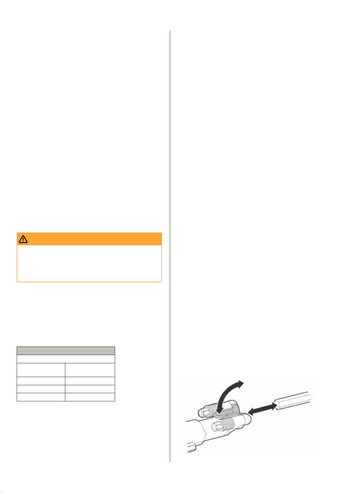
Fitting the drill steel
1� Push the retainer outwards in the direction of the arrow (see
picture below), until the front portion of the retainer is able to
accommodate the drill steel collar.
2� Insert the drill in the chuck.
3� When the drill bottoms, push back the retainer to lock it.
5
Removing the drill steel
1� Push the retainer outwards in the direction of the arrow until
the drill steel collar disengages from the front of the retainer.
2� Pull the drill steel out.
3� Push back the retainer.
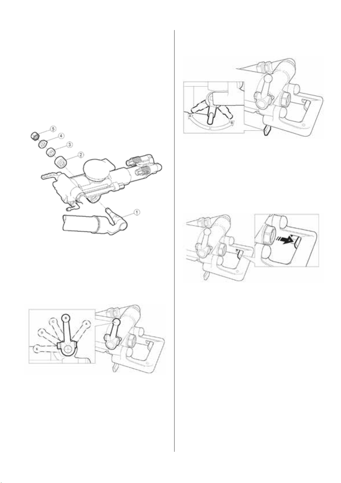
Attaching the pusher leg to the rock drill
• Mount the pusher leg (1), lock sleeve (2), rubber pad (3), washer
(4) and locking nut (5) in the order shown in the picture below.
•Turn the locking nut clockwise with a wrench until you hear a
"click".
Controls
Throttle lever
The rock drill is equipped with a throttle lever for regulating both
the compressed air to the percussion mechanism and the flushing
water.
A� Extra blowing, water flushing off, impact and rotation off.
B� Stop position, air and water off
C� Low throttle, air to pusher leg, water flushing
D� Medium throttle
E� Full throttle
Feed control
Adjust the feed force by means of the feed control lever as fol-
lows:
A� Pushing the lever in this direction will increase feed force.
B� Pulling the lever in this direction will decrease feed force
Trigger
When the trigger (A) is pushed in, the feed force stops abruptly
and the setting on the feed control lever is overridden.The piston
rod in the pusher leg retracts automatically.This function is used
for example to adjust the height of the rock drill, when rigging
up the pusher leg, or when there is a tendency to jam. When the
trigger is released, the feed control setting is activated again.
Oil regulating valve
Oil dosing is controlled using a screwdriver.Tighten the nut after
regulation.
Check that sufficient lubrication is obtained by putting your hand
in front of the exhaust port while adjusting the regulating valve.
If the hand is covered by a thin film of oil after a few seconds, the
lubricator has been correctly adjusted.Too much oil will have neg-
ative effects on the operation whilst too little will result in damage
to parts as the temperature rises during operation.
The amount of oil going into the rock drill increases when turning
the valve counter clockwise, and it decreases when turning the
valve clockwise. Oil consumption is 2.5–6 ml/minute.
Drilling
Starting the rock drill
1� Open the main valve for compressed air.
2� Open the cock for the flushing water.
3� Adjust the feed control lever to give a suitable feed force for
collaring the hole.
4� Align the rock drill so that the drill steel touches the desired
collaring point.

6
5� Move the throttle lever forward a little, which will start water
flushing, percussion and rotation.
6� Collar the hole with reduced feed force.
7� Move the throttle lever fully forward once the drill steel has
gained a secure footing in the rock.
8� Adjust the feed force using the control lever so that the maxi-
mum penetration rate is obtained.
Note! Do not bend the drill steel as this will increase wear of the
shank bushing and piston. It can also affect drilling efficiency and
increase the risk of drill steel breakage.
Stopping the rock drill
Pull the throttle lever backwards, which will stop percussion, rota-
tion and flushing water.
Checking the lubrication
The chuck and drill steel shank must always be covered by a film
of oil.
Re-positioning the pusher leg
1� Switch off the rock-drill percussion and flushing using the
throttle lever.
2� Press the trigger, whereupon the piston rod is pulled back into
the pusher-leg cylinder automatically.
3� Re-position the pusher leg.
4� Release the trigger, whereupon the piston rod will move out-
wards again.
5� Move the throttle lever forward into the working position.
Note!The feed control lever does not need to be touched through-
out this operation.
Blow-cleaning the drill hole
When blow-cleaning, particles and dirty flushing water can
emerge at speed from the drill hole.
• Move to the side and cover your eyes before starting to blow-
clean the drill hole.
• Always wear impact resistant eye protection with side protec-
tion to avoid injury.
• Make sure that no co-workers are in range when blow-cleaning.
CAUTION
If powerful blow-cleaning of the drill hole is required, turn the
throttle lever fully backwards beyond the stop position for extra
blowing whereupon the rock drill stops.This can be done during
drilling. When the drill hole is clean, turn the throttle lever for-
wards again to re-start the rock drill.
When you have finished drilling
Run the rock drill at medium speed when retracting the drill steel
from the drilled hole.
Lay down the rock drill on a stone, wooden plank or similar ob-
ject, so as to prevent drill cuttings and other foreign matter from
entering the chuck.
Turn off the water pressure before the air pressure. Run the rock
drill for a few seconds to clean out water and moisture after the
water has been shut off.
Maintenance
Regular maintenance is a prerequisite for machine safety. Replace
damaged and worn components in good time.
Check the machine and drill steel for wear and damage at regular
intervals. Do not use a very worn or damaged drill steel.
When cleaning mechanical parts with a solvent, make sure that
you comply with current health and safety regulations and ensure
that there is sufficient ventilation.
Daily maintenance, regular checking of wearing parts and carrying
out repairs in good time prevents breakdowns and increases the
service life of the machine.
• Make sure that no foreign matter enters the machine.
• Always hose down and wipe clean the rock drill and pusher leg
after use.
Once a shift (after 8 hours of operation)
• Check the wear in the chuck bushing. If the wear limit has been
exceeded, the drill steel shank will wear more quickly, or become
deformed.This will lead to stoppages and increased drill steel
consumption.
• Check the tightness of the side bolt nuts.
• Check the rock drill's connection to the pusher leg.
• Check the hoses, couplings and controls for leakage and dam-
age.
• Check that the rock drill and pusher leg are receiving enough
lubrication. Fill the lubricator as necessary.
• Every day before using the drill, blow out the air hose to clear it
from accumulated dirt and moisture.
• Drain the water separator.
• Check the air and water pressure. Make sure that the water pres-
sure is at least 1 bar lower than the air pressure.
Once a week (after 40 hours of operation)
Carry out a basic check of all functions of the drilling equipment.
Once a month (after 200 hours of operation)
• Send the rock drill to a workshop for inspection. The local oper-
ating conditions will determine whether or not this is a suitable
interval for overhauling the drill.
• Dismantle and clean the lubricator.
• Clean out the water separator.
Selection of spare parts
Use only genuine parts for replacement, to ensure stable per-
formance. Do not use pattern parts, which not only have a short
working life but also cause consequential damage to other parts,
due to differing measurements and methods of manufacturing.
Storage
• Always oil the rock drill and pusher leg well before you put them
into storage.
• Store the rock drill and pusher leg in a clean and dry place.
• In the case of long-term storage, pour a quantity of oil directly
into the rock-drill's air intake and then turn on the air briefly.This
will protect the machine from corrosion.
• Protect the chuck using a wooden plug or a clean piece of cotton
waste.
Scrapping and waste disposal
Used and worn-out machines must be disposed of in such a way
that as much of the material as possible can be recycled and the
impact on the environment is kept to a minimum.

7
Trouble shooting
Problem Cause Solution
Decreased
penetration rate
Air leakage in hoses, couplings Change packings, and where required, change parts in the
throttle valve
Shank sleeve Check the shank sleeve for excessive wear. Replace if
necessary.
Air leakage due to worn piston/cylinder Replace the piston and/or cylinder
Air leakage due to worn guide sleeve/pilot guide Change the worn part
Insufficient feed
force
Piston rod seal (in pusher leg) worn or deformed Change the seal
O-rings on pusher leg coupling worn or deformed Change the o-ring
Poor rotation Splines of the rifle nut worn Replace the rifle nut if the splines are worn
Splines of the rifle bar worn down Replace the rifle bar when needed
Splines on the piston worn down Replace the piston when needed
The toothing in the ratchet housing is worn out Replace the ratchet housing if the tooth housing is so worn
that the pawls have difficulty catching
The toothing in the ratchet wheel is worn out Replace the ratchet wheel if the toothing is so worn that the
pawls have difficulty catching
Chuck nut worn out Replace the chuck nut if the splines have been worn to 1/2 of
the spline width
Pawls worn Replace all pawls, all pawl springs and all pawl pins
Uneven running Piston has seized in the guide sleeve or the piston
guide
Replace the guide sleeve/piston guide. If required, polish
the piston. Check the piston for heat damage such as blue
colouring and/or fissures. If it is damaged in this way,
replace the piston as well
Dirty or damaged main valve. Caused by impurities
or foreign matter entering the drill with the
compressed air
Clean and polish the valve so that it seals against the
corresponding cylindrical and plane sealing surfaces. If this
is not possible because the defects are too serious, the valve
must be replaced
Freezing. Caused by leakage in the flushing system
or by excess water in the compressed air or by
excessive water pressure
Check the flushing tubes and seals and the water pressure.
Drain water from the compressed air system. If the problem
continues,
fit a water separator in the airline system.
Uneven running
(continued)
The side bolts are unevenly or insufficiently
tightened. Can cause the various parts to lose their
alignment, resulting in the seizure of the movable
parts. Abnormal strains on the side bolt may result
in fracture at the threads.
Check and repair any damage to the contact points and
tighten the bolts with the correct tightening torque
The drill gets hot Lack of oil Add oil and check that it runs through. It is not sufficient
that there is oil in the exhaust air. There must also be an oil
coating on the shank of the drill steel.
Freezing High level of humidity in the compressed air Use water traps
Water pressure higher than the air pressure Lower the water pressure
Water pipe
breakage
Misalignment of the shank Change drill steel or shank sleeve or both
Damaged flushing hole in the shank Change drill steel
Chipping of the
piston tip
Misalignment of the shank Change the drill steel or shank sleeve or both
Excessive wear of the piston tip Change piston
Spline breakage
Lack of lubrication Lower the water pressure if it is the same as or greater than
the air pressure
Increase lubrication or change oil
Dirt intrusion (specially when drilling upwards) Increase service intervals
Piston breakage
Lack of lubrication Lower the water pressure if it is the same as or greater than
the air pressure
Increase lubrication or change oil
Uneven tension in the side bolts Tighten the bolts correctly
Worn guide sleeve/piston guide (can be confirmed
by the cushion test)
Change the worn part
Side bolt breakage Uneven tension on the bolts Tighten the bolts correctly

1234
8
9
6
7
10
11
12
13
15 14
19
5
16
17
18
20
21
22
23
24
25
27
26
28
29
30
31
32
33
38 39
40 41
42
44
46
45
47
43
48
49
9
50
51
52
55
54
53
56
58
58
59
60
61
63
63 64
64
62
66
65
57
67
69
68
70
71
72
43
37
36
34
35
9853 1258 01 2013.08
Secoroc YT27 Pneumatic rock drill
Atlas Copco Secoroc AB
Box 521, SE-737 25 Fagersta, Sweden
Phone +46 223 461 00
www.atlascopco.com
Ref. Description Qty Prod. No. Product code
1 Right handle 1 96000163 9603-1-3312310152
2 Shockproof handle 1 96000164 9603-1-3312310153
3 Left handle 1 96000165 9603-1-3312310154
4 Roll pin 1 96000527 9605-1-3312310708
5 Trigger 1 96000162 9603-1-3312310151
6 Circlip 1 96000183 9605-1-3312310173
7 Spring cap 1 96000169 9605-1-3312310159
8 Spring 1 96000170 9605-1-3312310160
9 O seal ring 2 96000482 9605-1-3312310627
10 Water valve 1 96000173 9605-1-3312310163
11 O seal ring 2 96000489 9605-1-3312310642
12 Rubber pad 1 96000175 9605-1-3312310165
13 Water valve body 1 96000148 9603-1-3312310137
14 O seal ring 2 96000502 9605-1-3312310671
15 Pad 1 96000184 9605-1-3312310174
16 Water tube sleeve 1 96000149 9603-1-3312310138
17 Water tube 1 96000172 9605-1-3312310162
18 Air tube assembly 1 96000150 9603-1-3312310139
19 Air tube pad 1 96000176 9605-1-3312310166
20 Back head 1 96000147 9603-1-3312310136
21 Dowel pin 1 96000180 9605-1-3312310170
22 Spring 1 96000179 9605-1-3312310169
23 Ratchet pawl 4 96000166 9605-1-3312310155
24 Conical spring 4 96000167 9605-1-3312310156
25 Rifle bar 1 96000138 9603-1-3312310126
26 Ratchet 1 96000131 9603-1-3312310119
27 Dowel pin 1 96000135 9603-1-3312310123
28 Valve cover 1 96000142 9603-1-3312310130
29 Valve 1 96000133 9603-1-3312310121
30 Valve chest 1 96000132 9603-1-3312310120
31 Valve sleeve 1 96000134 9603-1-3312310122
32 Rifle nut 1 96000814 9600-1-3312310009
33 Piston 1 96000139 9603-1-3312310127
34 Fixing pin 1 96000177 9605-1-3312310167
35 Operating handle 1 96000152 9603-1-3312310141
36 Spring pad 1 96000534 9605-1-3312310716
Ref. Description Qty Prod. No. Product code
37 Hex nut 1 96000524 9605-1-3312310704
38 Spring 1 96000157 9603-1-3312310146
39 Pressure regulating valve 1 96000159 9603-1-3312310148
40 Expansion ring 2 96000158 9603-1-3312310147
41 Retaining ring 1 96000160 9603-1-3312310149
42 Change over valve 1 96000161 9603-1-3312310150
43 O seal ring 2 96000486 9605-1-3312310633
44 Control valve 1 96000153 9603-1-3312310142
45 Pad 1 96000174 9605-1-3312310164
46 Retaining ring 1 96000182 9605-1-3312310172
47 Air pipe nut 1 96000823 9600-1-3312310020
48 Air pipe swivel 1 96000825 9600-1-3312310022
49 Retaining ring 1 96000156 9603-1-3312310145
50 Water pipe nut 1 96000155 9603-1-3312310144
51 O seal ring 2 96000499 9605-1-3312310667
52 Water pipe connector 1 96000154 9603-1-3312310143
53 Cylinder 1 96000140 9603-1-3312310128
54 Muffler 1 96000137 9603-1-3312310125
55 Hoop 1 96000542 9605-1-3312310725
56 Guiding sleeve 1 96000141 9603-1-3312310129
57 Side bolt 2 96000151 9603-1-3312310140
58 Hex thick nut 2 96000518 9605-1-3312310697
59 Rotation nut 1 96000146 9603-1-3312310135
60 Rotation sleeve 1 96000144 9603-1-3312310133
61 Shank bushing 1 96000145 9603-1-3312310134
62 Front head 1 96000143 9603-1-3312310131
63 Hex lock nut 2 96000531 9605-1-3312310713
64 Drill retainer spring 2 96000818 9600-1-3312310013
65 Drill retainer bolt 2 96000634 9600-1-3312311820
66 Drill retainer 1 96000635 9600-1-3312311821
67 Pipe connector 1 96000187 9605-1-3312310177
68 Conical hose nipple 1 96000186 9605-1-3312310176
69 Wing nut 1 96000185 9605-1-3312310175
70 Hoop 1 96000540 9605-1-3312310723
71 Sealing sleeve 2 96000543 9605-1-3312310726
72 Large sealing sleeve 1 96000544 9605-1-3312310727
1234
8
9
6
7
10
11
12
13
15 14
19
5
16
17
18
20
21
22
23
24
25
27
26
28
29
30
31
32
33
38 39
40 41
42
44
46
45
47
43
48
49
9
50
51
52
55
54
53
56
58
58
59
60
61
63
63 64
64
62
66
65
57
67
69
68
70
71
72
43
37
36
34
35
9853 1258 01 2013.08
Secoroc YT27
Pneumatic rock drill
Atlas Copco Secoroc AB
Box 521, SE-737 25 Fagersta, Sweden
Phone +46 223 461 00
www.atlascopco.com
Ref. Description Qty Prod. No. Product code
1 Right handle 1 96000163 9603-1-3312310152
2 Shockproof handle 1 96000164 9603-1-3312310153
3 Left handle 1 96000165 9603-1-3312310154
4 Roll pin 1 96000527 9605-1-3312310708
5 Trigger 1 96000162 9603-1-3312310151
6 Circlip 1 96000183 9605-1-3312310173
7 Spring cap 1 96000169 9605-1-3312310159
8 Spring 1 96000170 9605-1-3312310160
9 O seal ring 2 96000482 9605-1-3312310627
10 Water valve 1 96000173 9605-1-3312310163
11 O seal ring 2 96000489 9605-1-3312310642
12 Rubber pad 1 96000175 9605-1-3312310165
13 Water valve body 1 96000148 9603-1-3312310137
14 O seal ring 2 96000502 9605-1-3312310671
15 Pad 1 96000184 9605-1-3312310174
16 Water tube sleeve 1 96000149 9603-1-3312310138
17 Water tube 1 96000172 9605-1-3312310162
18 Air tube assembly 1 96000150 9603-1-3312310139
19 Air tube pad 1 96000176 9605-1-3312310166
20 Back head 1 96000147 9603-1-3312310136
21 Dowel pin 1 96000180 9605-1-3312310170
22 Spring 1 96000179 9605-1-3312310169
23 Ratchet pawl 4 96000166 9605-1-3312310155
24 Conical spring 4 96000167 9605-1-3312310156
25 Rifle bar 1 96000138 9603-1-3312310126
26 Ratchet 1 96000131 9603-1-3312310119
27 Dowel pin 1 96000135 9603-1-3312310123
28 Valve cover 1 96000142 9603-1-3312310130
29 Valve 1 96000133 9603-1-3312310121
30 Valve chest 1 96000132 9603-1-3312310120
31 Valve sleeve 1 96000134 9603-1-3312310122
32 Rifle nut 1 96000814 9600-1-3312310009
33 Piston 1 96000139 9603-1-3312310127
34 Fixing pin 1 96000177 9605-1-3312310167
35 Operating handle 1 96000152 9603-1-3312310141
36 Spring pad 1 96000534 9605-1-3312310716
Ref. Description Qty Prod. No. Product code
37 Hex nut 1 96000524 9605-1-3312310704
38 Spring 1 96000157 9603-1-3312310146
39 Pressure regulating valve 1 96000159 9603-1-3312310148
40 Expansion ring 2 96000158 9603-1-3312310147
41 Retaining ring 1 96000160 9603-1-3312310149
42 Change over valve 1 96000161 9603-1-3312310150
43 O seal ring 2 96000486 9605-1-3312310633
44 Control valve 1 96000153 9603-1-3312310142
45 Pad 1 96000174 9605-1-3312310164
46 Retaining ring 1 96000182 9605-1-3312310172
47 Air pipe nut 1 96000823 9600-1-3312310020
48 Air pipe swivel 1 96000825 9600-1-3312310022
49 Retaining ring 1 96000156 9603-1-3312310145
50 Water pipe nut 1 96000155 9603-1-3312310144
51 O seal ring 2 96000499 9605-1-3312310667
52 Water pipe connector 1 96000154 9603-1-3312310143
53 Cylinder 1 96000140 9603-1-3312310128
54 Muffler 1 96000137 9603-1-3312310125
55 Hoop 1 96000542 9605-1-3312310725
56 Guiding sleeve 1 96000141 9603-1-3312310129
57 Side bolt 2 96000151 9603-1-3312310140
58 Hex thick nut 2 96000518 9605-1-3312310697
59 Rotation nut 1 96000146 9603-1-3312310135
60 Rotation sleeve 1 96000144 9603-1-3312310133
61 Shank bushing 1 96000145 9603-1-3312310134
62 Front head 1 96000143 9603-1-3312310131
63 Hex lock nut 2 96000531 9605-1-3312310713
64 Drill retainer spring 2 96000818 9600-1-3312310013
65 Drill retainer bolt 2 96000634 9600-1-3312311820
66 Drill retainer 1 96000635 9600-1-3312311821
67 Pipe connector 1 96000187 9605-1-3312310177
68 Conical hose nipple 1 96000186 9605-1-3312310176
69 Wing nut 1 96000185 9605-1-3312310175
70 Hoop 1 96000540 9605-1-3312310723
71 Sealing sleeve 2 96000543 9605-1-3312310726
72 Large sealing sleeve 1 96000544 9605-1-3312310727
8

1234
8
9
6
7
10
11
12
13
15 14
19
5
16
17
18
20
21
22
23
24
25
27
26
28
29
30
31
32
33
38 39
40 41
42
44
46
45
47
43
48
49
9
50
51
52
55
54
53
56
58
58
59
60
61
63
63 64
64
62
66
65
57
67
69
68
70
71
72
43
37
36
34
35
9853 1258 01 2013.08
Secoroc YT27 Pneumatic rock drill
Atlas Copco Secoroc AB
Box 521, SE-737 25 Fagersta, Sweden
Phone +46 223 461 00
www.atlascopco.com
Ref. Description Qty Prod. No. Product code
1 Right handle 1 96000163 9603-1-3312310152
2 Shockproof handle 1 96000164 9603-1-3312310153
3 Left handle 1 96000165 9603-1-3312310154
4 Roll pin 1 96000527 9605-1-3312310708
5 Trigger 1 96000162 9603-1-3312310151
6 Circlip 1 96000183 9605-1-3312310173
7 Spring cap 1 96000169 9605-1-3312310159
8 Spring 1 96000170 9605-1-3312310160
9 O seal ring 2 96000482 9605-1-3312310627
10 Water valve 1 96000173 9605-1-3312310163
11 O seal ring 2 96000489 9605-1-3312310642
12 Rubber pad 1 96000175 9605-1-3312310165
13 Water valve body 1 96000148 9603-1-3312310137
14 O seal ring 2 96000502 9605-1-3312310671
15 Pad 1 96000184 9605-1-3312310174
16 Water tube sleeve 1 96000149 9603-1-3312310138
17 Water tube 1 96000172 9605-1-3312310162
18 Air tube assembly 1 96000150 9603-1-3312310139
19 Air tube pad 1 96000176 9605-1-3312310166
20 Back head 1 96000147 9603-1-3312310136
21 Dowel pin 1 96000180 9605-1-3312310170
22 Spring 1 96000179 9605-1-3312310169
23 Ratchet pawl 4 96000166 9605-1-3312310155
24 Conical spring 4 96000167 9605-1-3312310156
25 Rifle bar 1 96000138 9603-1-3312310126
26 Ratchet 1 96000131 9603-1-3312310119
27 Dowel pin 1 96000135 9603-1-3312310123
28 Valve cover 1 96000142 9603-1-3312310130
29 Valve 1 96000133 9603-1-3312310121
30 Valve chest 1 96000132 9603-1-3312310120
31 Valve sleeve 1 96000134 9603-1-3312310122
32 Rifle nut 1 96000814 9600-1-3312310009
33 Piston 1 96000139 9603-1-3312310127
34 Fixing pin 1 96000177 9605-1-3312310167
35 Operating handle 1 96000152 9603-1-3312310141
36 Spring pad 1 96000534 9605-1-3312310716
Ref. Description Qty Prod. No. Product code
37 Hex nut 1 96000524 9605-1-3312310704
38 Spring 1 96000157 9603-1-3312310146
39 Pressure regulating valve 1 96000159 9603-1-3312310148
40 Expansion ring 2 96000158 9603-1-3312310147
41 Retaining ring 1 96000160 9603-1-3312310149
42 Change over valve 1 96000161 9603-1-3312310150
43 O seal ring 2 96000486 9605-1-3312310633
44 Control valve 1 96000153 9603-1-3312310142
45 Pad 1 96000174 9605-1-3312310164
46 Retaining ring 1 96000182 9605-1-3312310172
47 Air pipe nut 1 96000823 9600-1-3312310020
48 Air pipe swivel 1 96000825 9600-1-3312310022
49 Retaining ring 1 96000156 9603-1-3312310145
50 Water pipe nut 1 96000155 9603-1-3312310144
51 O seal ring 2 96000499 9605-1-3312310667
52 Water pipe connector 1 96000154 9603-1-3312310143
53 Cylinder 1 96000140 9603-1-3312310128
54 Muffler 1 96000137 9603-1-3312310125
55 Hoop 1 96000542 9605-1-3312310725
56 Guiding sleeve 1 96000141 9603-1-3312310129
57 Side bolt 2 96000151 9603-1-3312310140
58 Hex thick nut 2 96000518 9605-1-3312310697
59 Rotation nut 1 96000146 9603-1-3312310135
60 Rotation sleeve 1 96000144 9603-1-3312310133
61 Shank bushing 1 96000145 9603-1-3312310134
62 Front head 1 96000143 9603-1-3312310131
63 Hex lock nut 2 96000531 9605-1-3312310713
64 Drill retainer spring 2 96000818 9600-1-3312310013
65 Drill retainer bolt 2 96000634 9600-1-3312311820
66 Drill retainer 1 96000635 9600-1-3312311821
67 Pipe connector 1 96000187 9605-1-3312310177
68 Conical hose nipple 1 96000186 9605-1-3312310176
69 Wing nut 1 96000185 9605-1-3312310175
70 Hoop 1 96000540 9605-1-3312310723
71 Sealing sleeve 2 96000543 9605-1-3312310726
72 Large sealing sleeve 1 96000544 9605-1-3312310727
9

10
Notes

11
Notes

9866 0023 01 Subjected to alterations without prior notice. © Epiroc Drilling Tools AB. All rights reserved. 2017.12.
United in performance.
Inspired by innovation.
Performance unites us, innovation inspires us, and
commitment drives us to keep moving forward.
Count on Epiroc to deliver the solutions you need to
succeed today and the technology to lead tomorrow.
epiroc.com
Epiroc Drilling Tools AB
Box 521, SE-737 25 Fagersta, Sweden
Phone: +46 223 461 00
Table of contents
Other Epiroc Drill manuals


Popular Drill manuals by other brands

Hitachi
Hitachi DS 18DGL Handling instructions

BDS
BDS MAB 825 V Translation of the original operating instructions

Metabo HPT
Metabo HPT DS 18DC Safety instructions and instruction manual

Black & Decker
Black & Decker HD450 instruction manual

HIKOKI
HIKOKI DV 18DSDL Handling instructions

Clas Ohlson
Clas Ohlson DJC123-108-UK manual


