Epiroc RD 100 Maintenance and service guide

Safety and operating instructions
Rock drills
RD 100
© Construction Tools PC AB | 9800 1365 01 | 2018-01-01
Original instructions


Contents
Introduction .................................................................................................................................................... 5
About the Safety and operating instructions .............................................................................................. 5
Safety instructions ......................................................................................................................................... 5
Safety signal words .................................................................................................................................. 5
Personal precautions and qualifications ................................................................................................ 5
Installation, storage, maintenance and disposal .................................................................................... 5
Testing ................................................................................................................................................... 5
Personal protective equipment .............................................................................................................. 5
Drugs, alcohol or medication ................................................................................................................. 6
Installation, precautions .......................................................................................................................... 6
Operation, precautions ............................................................................................................................ 7
Maintenance, precautions ...................................................................................................................... 11
Storage, precautions .............................................................................................................................. 11
Overview ....................................................................................................................................................... 12
Design and function ............................................................................................................................... 12
Main parts ................................................................................................................................................ 12
Labels ...................................................................................................................................................... 12
Data plate ............................................................................................................................................ 13
Labels on the accumulator ................................................................................................................... 13
Safety label .......................................................................................................................................... 13
Installation .................................................................................................................................................... 13
Hoses and connections ......................................................................................................................... 13
Hoses ....................................................................................................................................................... 14
Quick-release couplings ........................................................................................................................ 14
Hydraulic oil ............................................................................................................................................ 14
Methods to prevent freezing .................................................................................................................. 14
Pressure adjustment .............................................................................................................................. 14
Hydraulic oil pressure .......................................................................................................................... 14
Water pressure .................................................................................................................................... 14
Drill steel .................................................................................................................................................. 14
Before fitting the drill steel ................................................................................................................... 15
Changing drill steel .............................................................................................................................. 15
Operation ...................................................................................................................................................... 16
Preparations before starting .................................................................................................................. 16
Check the drilling equipment ............................................................................................................... 16
Attaching pusher leg to rock drill .......................................................................................................... 16
Controls ................................................................................................................................................... 17
Water flushing lever ............................................................................................................................. 17
Throttle lever ........................................................................................................................................ 17
Twist handle ......................................................................................................................................... 17
Start and stop .......................................................................................................................................... 17
Drilling .................................................................................................................................................. 17
Starting the rock drill ............................................................................................................................ 18
Stopping the rock drill .......................................................................................................................... 18
Operating ................................................................................................................................................. 18
Re-position of the pusher leg ............................................................................................................... 18
Flush-cleaning the drill hole ................................................................................................................. 19
When taking a break ............................................................................................................................... 19
Maintenance ................................................................................................................................................. 19
Every day ................................................................................................................................................. 19
Checking for wear ................................................................................................................................... 19
RD 100 Contents
© Construction Tools PC AB | 9800 1365 01 | 2018-01-01
Original instructions
3

Replace the drill steel bushings ............................................................................................................ 20
Every 100 hours of operation or 3 times per year ............................................................................... 21
Storage .......................................................................................................................................................... 21
Disposal ........................................................................................................................................................ 21
Troubleshooting ........................................................................................................................................... 22
Technical data .............................................................................................................................................. 23
Machine data ........................................................................................................................................... 23
Noise and vibration declaration statement .......................................................................................... 23
Noise and vibration data ........................................................................................................................ 24
EC Declaration of Conformity ..................................................................................................................... 25
EC Declaration of Conformity (EC Directive 2006/42/EC) ................................................................... 25
Contents RD 100
4 © Construction Tools PC AB | 9800 1365 01 | 2018-01-01
Original instructions

Introduction
Epiroc is a leading productivity partner for the
mining, infrastructure and natural resources
industries. With cutting-edge technology, Epiroc
develops and produces innovative drill rigs, rock
excavation and construction equipment, and
provides world-class service and consumables.
The company was founded in Stockholm, Sweden,
and has passionate people supporting and
collaborating with customers in more than 150
countries.
Construction Tools PC AB
Box 703
391 27 Kalmar
Sweden
About the Safety and
operating instructions
The aim of the instructions is to provide you with
knowledge of how to use the power packs in an
efficient, safe way. The instructions also give you
advice and tell you how to perform regular
maintenance on the power packs.
Before using the power packs for the first time you
must read these instructions carefully and
understand all of them.
Safety instructions
To reduce the risk of serious injury or death to
yourself or others, read and understand the Safety
and operating instruction before installing,
operating, repairing, maintaining, or changing
accessories on the machine.
Post this Safety and operating instruction at work
locations, provide copies to employees, and make
sure that everyone reads the Safety and operating
instruction before operating or servicing the
machine. For professional use only.
In addition, the operator or the operator's employer
must assess the specific risks that may be present
as a result of each use of the machine.
Safety signal words
The safety signal words Danger, Warning and
Caution have the following meanings:
DANGER Indicates a hazardous
situation which, if not avoided,
will result in death or serious
injury.
WARNING Indicates a hazardous
situation which, if not avoided,
could result in death or
serious injury.
CAUTION Indicates a hazardous
situation which, if not avoided,
could result in minor or
moderate injury.
Personal precautions and
qualifications
Only qualified and trained persons may operate or
maintain the machine. They must be physically
able to handle the bulk, weight, and power of the
machine. Always use your common sense and
good judgement.
Installation, storage, maintenance and
disposal
Installation, storage, maintenance and disposal of
the machine may only be undertaken by persons
who:
◆are aware of all the relevant national safety
instructions and accident prevention
instructions
◆and have read and understood the Safety and
operating instructions.
Testing
Testing of the hydraulic installation must only be
carried out by professional technicians. The
technicians must be authorised to approve a
hydraulic installation in accordance with national
directives.
Personal protective equipment
Always use approved protective equipment.
Operators and all other persons in the working
area must wear protective equipment, including at
a minimum:
•Protective helmet
•Hearing protection
•Impact resistant eye protection with side
protection
•Respiratory protection when appropriate
•Protective gloves
•Proper protective boots
•Appropriate work overall or similar clothing (not
loose-fitting) that covers your arms and legs.
RD 100 Safety and operating instructions
© Construction Tools PC AB | 9800 1365 01 | 2018-01-01
Original instructions
5

Drugs, alcohol or medication
WARNING Drugs, alcohol or medication
Drugs, alcohol or medication may impair your
judgment and powers of concentration. Poor
reactions and incorrect assessments can lead to
severe accidents or death.
►Never use the machine when you are tired or
under the influence of drugs, alcohol or
medication.
►No person who is under the influence of drugs,
alcohol or medication may operate the
machine.
Installation, precautions
DANGER Compressed gas, explosion
hazard
The accumulator is pressurized even when the
hydraulic system is shut off. To dismount the
accumulator without first releasing the nitrogen gas
can cause serious personal injury or death.
►Fill the high-pressure accumulator with nitrogen
(N2) only.
►Only authorised personnel are qualified to work
with the accumulator.
WARNING Whipping hose
Hoses under pressure can whip uncontrollably if
the hose connection becomes loose. A whipping
hose can cause severe injuries. To reduce this risk:
►Turn of the power pack before loosening the
connection of a hose.
►Check that the hose and the connections are
not damaged.
►Never carry or drag the machine by the hoses.
WARNING Hydraulic oil at high pressure
Thin jets of hydraulic oil under high pressure can
penetrate the skin and cause permanent injury.
►Immediately consult a doctor if hydraulic oil has
penetrated the skin.
►Never use your fingers to check for hydraulic
fluid leaks.
►Keep your face away from any possible leaks.
WARNING Hydraulic oil
Spilled hydraulic oil can cause burns, accidents
due to slippery conditions and will also harm the
environment.
►Take care of all spilled oil and handle it
according to your safety and environmental
regulations.
►Never dismount the hydraulic machine when
the hydraulic oil is hot.
►Never run any hydraulic lines for attachment of
the hydraulic machine through the drivers cab.
WARNING Ejected working tool
If the tool retainer on the machine is not in a locked
position, the working tool can be ejected with force,
which can cause personal injury.
►Never start the machine while changing the
working tool.
►Before changing the working tool or
accessories, stop the machine and turn off the
power source.
►Never point the working tool at yourself or
anyone else.
►Make sure that the working tool is fully inserted
and the tool retainer is in a locked position
before the machine is started.
►Check the locking function by pulling the
working tool outwards forcefully.
WARNING Moving or slipping insertion tool
An incorrect dimension of the inserted tool’s shank
can result in that the inserted tool is lost or is
slipping out during operation. Risk of severe injury
or crushed hands and fingers.
►Check that the insertion tool has the shank
length and dimensions that the machine is
intended for.
►Never use an insertion tool without a collar.
WARNING Injured hands
There is a risk of crushing fingers when changing
the working tool. To recuce this risk:
►Never inspect, clean, install, or remove the
working tool while the power source is
connected.
►Never put the fingers between the tool retainer
and the chuck.
CAUTION Skin eczema
Hydraulic oil can cause eczema if it comes in
contact with the skin.
►Avoid getting hydraulic oil on your hands.
►Always use protective gloves when working
with hydraulic oil.
►Wash hands after contact with hydraulic oil.
Safety and operating instructions RD 100
6 © Construction Tools PC AB | 9800 1365 01 | 2018-01-01
Original instructions

CAUTION Moving parts
Risk for crushed hands and fingers.
►Never check bores or passages with hands or
fingers.
Operation, precautions
DANGER Explosion hazard
If a warm insertion tool comes into contact with
explosives, an explosion could occur. During
operation with certain materials as well as use of
certain materials in machine parts, sparks and
ignition can occur. Explosions will lead to severe
injuries or death.
►Never operate the machine in any explosive
environment.
►Never use the machine near flammable
materials, fumes or dust.
►Make sure that there are no undetected
sources of gas or explosives.
►Never drill in an old hole.
DANGER Electrical hazard
The machine is not electrically insulated. If the
machine comes into contact with electricity, serious
injuries or death may result.
►Never operate the machine near any electric
wire or other source of electricity.
►Make sure that there are no concealed wires or
other sources of electricity in the working area.
WARNING Operating pressure
If the maximum operating pressure for the
hydraulic machine is exceeded, the accumulator
can be over charged which can result in material
damage and personal injury.
►Always run the hydraulic machine with the
correct operating pressure. See "Technical
data".
WARNING Unexpected movements
The working tool is exposed to heavy strains when
the machine is used. The working tool may break
due to fatigue after a certain amount of use. If the
working tool breaks or gets stuck, there may be
sudden and unexpected movement that can cause
injuries. Furthermore, losing your balance or
slipping may cause injury.
►Make sure that you always keep a stable
position with your feet as far apart as your
shoulder width, and keeping a balanced body
weight.
►Always inspect the equipment prior to use.
Never use the equipment if you suspect that it
is damaged.
►Make sure that the handles are clean and free
of grease and oil.
RD 100 Safety and operating instructions
© Construction Tools PC AB | 9800 1365 01 | 2018-01-01
Original instructions
7

►Keep your feet away from the working tool.
►Stand firmly and always hold on to the machine
with both hands.
►Never drill in an old hole.
►Never start the machine when it is lying on the
ground.
►Never ‘ride’ on the machine with one leg over
the handle.
►Never strike or abuse the equipment.
►Check regularly for wear on the working tool,
and check whether there are any signs of
damage or visible cracks.
►Pay attention and look at what you are doing.
WARNING Stalling hazard
If the working tool gets caught during operation,
the whole machine may will start to rotate if you
lose your grip on it. This unexpected rotation of the
entire machine may cause serious injury.
►Stand firmly and always hold onto the machine
with both hands.
►Make sure that the handle or handles are clean
and free from grease and oil.
►Never drill in an old hole.
WARNING Trapping hazard
There is risk of neck ware, hair, gloves and clothes
getting dragged into or caught by a rotating
insertion tool or accessories. This may cause
choking, scalping, lacerations or death. To reduce
the risk:
►Never grab or touch a rotating drill steel.
►Avoid wearing clothing, neck ware or gloves
that may get caught.
►Cover long hair with a hair net.
There is risk of getting trapped between the
machine and the roof/wall should the machine, for
any reason, tip over. There is also risk for crushed
hands and fingers when extending the pusher leg.
WARNING Dust and fume hazard
Dusts and/or fumes generated or dispersed when
using the machine may cause serious and
permanent respiratory disease, illness, or other
bodily injury (for example, silicosis or other
irreversible lung disease that can be fatal, cancer,
birth defects, and/or skin inflammation).
Some dusts and fumes created by drilling,
breaking, hammering, sawing, grinding and other
construction activities contain substances known to
the State of California and other authorities to
cause respiratory disease, cancer, birth defects, or
other reproductive harm. Some examples of such
substances are:
•Crystalline silica, cement, and other masonry
products.
•Arsenic and chromium from chemically-treated
rubber.
•Lead from lead-based paints.
Dust and fumes in the air can be invisible to the
naked eye, so do not rely on eye sight to
determine if there is dust or fumes in the air.
To reduce the risk of exposure to dust and fumes,
do all of the following:
►Perform site-specific risk assessment. The risk
assessment should include dust and fumes
created by the use of the machine and the
potential for disturbing existing dust.
►Use proper engineering controls to minimize the
amount of dust and fumes in the air and to
minimize build-up on equipment, surfaces,
clothing, and body parts. Examples of controls
include: exhaust ventilation and dust collection
systems, water sprays, and wet drilling. Control
dusts and fumes at the source where possible.
Make sure that controls are properly installed,
maintained and correctly used.
►Wear, maintain and correctly use respiratory
protection as instructed by your employer and
as required by occupational health and safety
regulations. The respiratory protection must be
effective for the type of substance at issue (and
if applicable, approved by relevant
governmental authority).
►Work in a well ventilated area.
►Operate and maintain the machine as
recommended in the safety and operating
instructions.
►Select, maintain and replace consumables/
working tools/ other accessory as
recommended in the safety and operating
instructions. Incorrect selection or lack of
maintenance of consumables/ inserted tools/
Safety and operating instructions RD 100
8 © Construction Tools PC AB | 9800 1365 01 | 2018-01-01
Original instructions

other accessories may cause an unnecessary
increase in dust or fumes.
►Wear washable or disposable protective clothes
at the worksite, and shower and change into
clean clothes before leaving the worksite to
reduce exposure of dust and fumes to yourself,
other persons, cars, homes, and other areas.
►Avoid eating, drinking, and using tobacco
products in areas where there is dust or fumes.
►Wash your hands and face thoroughly as soon
as possible upon leaving the exposure area,
and always before eating, drinking, using
tobacco products, or making contact with other
persons.
►Comply with all applicable laws and regulations,
including occupational health and safety
regulations.
►Participate in air monitoring, medical
examination programs, and health and safety
training programs provided by your employer or
trade organizations and in accordance with
occupational health and safety regulations and
recommendations. Consult with physicians
experienced with relevant occupational
medicine.
►Work with your employer and trade organization
to reduce dust and fume exposure at the
worksite and to reduce the risks. Effective
health and safety programs, policies and
procedures for protecting workers and others
against harmful exposure to dust and fumes
should be established and implemented based
on advice from health and safety experts.
Consult with experts.
►Residues of hazardous substances on the
machine can be a risk. Before undertaking any
maintenance on the machine clean it
thoroughly.
WARNING Hot water hazard
The flushing water can become hot and cause
burns. To reduce the risk of burns:
►Keep your body away from the hot water.
►Stop the machine and the power source
immediately.
►Wait until the machine and power source has
cooled down before carrying out maintenance
work.
WARNING Projectiles
Failure of the work piece, of accessories, or even
of the machine itself may generate high velocity
projectiles. During operating, splinters or other
particles from the working material may become
projectiles and cause personal injury by striking the
operator or other persons. To reduce these risk:
►Use approved personal protective equipment
and safety helmet, including impact resistant
eye protection with side protection.
►Make sure that no unauthorised persons
trespass into the working zone.
►Keep the workplace free from foreign objects.
►Ensure that the work piece is securely fixed.
WARNING Splinters hazard
Using the insertion tool as a hand struck tool can
result in splinters hitting the operator and can
cause personal injury.
►Never use an insertion tool as a hand struck
tool. They are specifically designed and heat-
treated to be used only in a machine.
WARNING Slipping, tripping and falling
hazards
There is a risk of slipping, tripping or falling, for
example tripping on hoses or on other objects.
Slipping, tripping or falling can cause injury. To
reduce this risk:
►Always make sure that no hose or other object
is in your way or in any other person's way.
►Always make sure you are in a stable position
with your feet as far apart as your shoulder
width and keeping a balanced body weight.
WARNING Motion hazards
When using the machine to perform work-related
activities, you may experience discomfort in the
hands, arms, shoulders, neck, or other parts of the
body.
►Adopt a comfortable posture while maintaining
secure footing and avoiding awkward off-
balanced postures.
►Changing posture during extended tasks may
help avoid discomfort and fatigue.
►In case of persistent or recurring symptoms,
consult a qualified health professional.
RD 100 Safety and operating instructions
© Construction Tools PC AB | 9800 1365 01 | 2018-01-01
Original instructions
9

WARNING Vibration hazards
Normal and proper use of the machine exposes
the operator to vibration. Regular and frequent
exposure to vibration may cause, contribute to, or
aggravate injury or disorders to the operator’s
fingers, hands, wrists, arms, shoulders and/or
nerves and blood supply or other body parts,
including debilitating and/or permanent injuries or
disorders that may develop gradually over periods
of weeks, months, or years. Such injuries or
disorders may include damage to the blood
circulatory system, damage to the nervous system,
damage to joints, and possibly damage to other
body structures.
If numbness, persistent recurring discomfort,
burning sensation, stiffness, throbbing, tingling,
pain, clumsiness, weakened grip, whitening of the
skin, or other symptoms occur at any time, when
operating the machine or when not operating the
machine, stop operating the machine, tell your
employer and seek medical attention. Continued
use of the machine after the occurrence of any
such symptom may increase the risk of symptoms
becoming more severe and/or permanent.
Operate and maintain the machine as
recommended in these instructions, to prevent an
unnecessary increase in vibration.
The following may help to reduce exposure to
vibration for the operator:
►Let the machine do the job. Use a minimum
hand grip consistent with proper control and
safe operation.
►If the machine has vibration absorbing handles,
keep them in a central position, avoid pressing
the handles into the end stops.
►When the percussion mechanism is activated,
the only body contact with the machine you
should have are your hands on the handle or
handles. Avoid any other contact, for example
supporting any part of the body against the
machine or leaning onto the machine trying to
increase the feed force. It is also important not
to keep the start and stop device engaged while
extracting the machine from the broken work
surface.
►Make sure that the working tool is well-
maintained , not worn out, and of the proper
size. Working tools that are not well-maintained,
or that are worn out, or that are not of the
proper size result in longer time to complete a
task (and a longer period of exposure to
vibration) and may result in or contribute to
higher levels of vibration exposure.
►Immediately stop working if the machine
suddenly starts to vibrate strongly. Before
resuming the work, find and remove the cause
of the increased vibrations.
►Never grab, hold or touch the chuck, drill stell or
drill bit when using the machine.
►Participate in health surveillance or monitoring,
medical exams and training programs offered
by your employer and when required by law.
►When working in cold conditions wear warm
clothing and keep hands warm and dry.
See the ”Noise and vibration declaration
statement” for the machine, including the declared
vibration values. This information can be found at
the end of these Safety and operating instructions.
WARNING Vibration hazard
Using inserted tools that do not fulfil the criteria
mentioned below, will result in a longer time to
complete a task, and may result in higher levels of
vibration exposure. A worn tool will also cause
increased working time.
►Make sure that the inserted tool is well-
maintained, not worn out and of the proper size.
►Always use a sharp tool in order to work
efficiently.
WARNING Concealed object hazard
During operating, concealed wires and pipes
constitute a danger that can result in serious injury.
►Check the composition of the material before
operating.
►Watch out for concealed cables and pipes for
example electricity, telephone, water, gas and
sewage lines etc.
►If the inserted tool seems to have hit a
concealed object, switch off the machine
immediately.
►Make sure that there is no danger before
continuing.
WARNING Involuntary start
Involuntary start of the machine may cause injury.
►Keep your hands away from the start and stop
device until you are ready to start the machine.
Safety and operating instructions RD 100
10 © Construction Tools PC AB | 9800 1365 01 | 2018-01-01
Original instructions

►Learn how the machine is switched off in the
event of an emergency.
►Stop the machine immediately in all cases of
power supply interruption.
WARNING Noise hazard
High noise levels can cause permanent and
disabling hearing loss and other problems such as
tinnitus (ringing, buzzing, whistling, or humming in
the ears). To reduce risks and prevent an
unnecessary increase in noise levels:
►Risk assessment of these hazards and
implementation of appropriate controls is
essential.
►Operate and maintain the machine as
recommended in these instructions.
►Select, maintain and replace the working tool as
recommended in these instructions.
►If the machine has a silencer, check that it is in
place and in good working condition.
►Always use hearing protection.
►Use damping material to prevent work pieces
from 'ringing'.
WARNING Choose right power pack
Handheld hydraulic rock drills are designed for
working together with Epiroc power packs. Use of
other power sources can lead to personal injury
and damage of the machine.
►Make sure that the power source you plan to
use is compatible with the rock drill, see section
"Technical data".
Maintenance, precautions
WARNING Machine modification
Any machine modification may result in bodily
injuries to yourself or others.
►Never modify the machine. Modified machines
are not covered by warranty or product liability.
►Always use approved original parts, tools, and
accessories.
►Change damaged parts immediately.
►Replace worn components in good time.
WARNING Working tool hazards
Accidental engagement of the start and stop
device during maintenance or installation can
cause serious injuries, when the power source is
connected.
►Never inspect, clean, install, or remove the
working tool while the power source is
connected.
CAUTION Hot working tool
The tip of the working tool can become hot and
sharp when used. Touching it can lead to burns
and cuts.
►Never touch a hot or sharp working tool.
►Wait until the working tool has cooled down
before carrying out maintenance work.
Storage, precautions
◆Keep the machine and tools in a safe place, out
of the reach of children and locked up.
RD 100 Safety and operating instructions
© Construction Tools PC AB | 9800 1365 01 | 2018-01-01
Original instructions
11
Overview
To reduce the risk of serious injury or death to
yourself or others, read the Safety instructions
section found on the previous pages of this
manual before operating the machine.
Design and function
RD 100 is a sturdy and reliable handheld hydraulic
rock drill designed for working together with pusher
leg, PL 100, and with power pack, PP 100. The
pusher leg support helps the operator to lift and
feed the rock drill during the drilling operation.
There are no limitations on the ambient
temperature on the working place as soon as the
used hydraulic fluid are within the needed
parameters. The temperature of the hydraulic fluid
and the hydraulic power are regulated by the PP
100.
RD 100 is designed for drilling of blast holes,
anchor holes, and for test drillings in for example
granite and concrete. It is suited for hole diameters
from Ø 25-42 mm (1-111⁄16 in.) and will, when using
hollow drill steels of the ISO-series 11-17, work
efficiently down to a maximum depth of 2.4 m (7.9 ft),
depending on the material. The drilling dust is
removed from the drill hole by means of flushing
water.
No other use is permitted. To choose the correct
working tool, see the spare part list.
A built-in torque limiter ensures that the operator
can hold the rock drill, if the drill steel gets stuck.
The rock drill is delivered with tail-hoses with 'Flat-
Face' quick-release couplings for easy connection
to the Epiroc power pack.
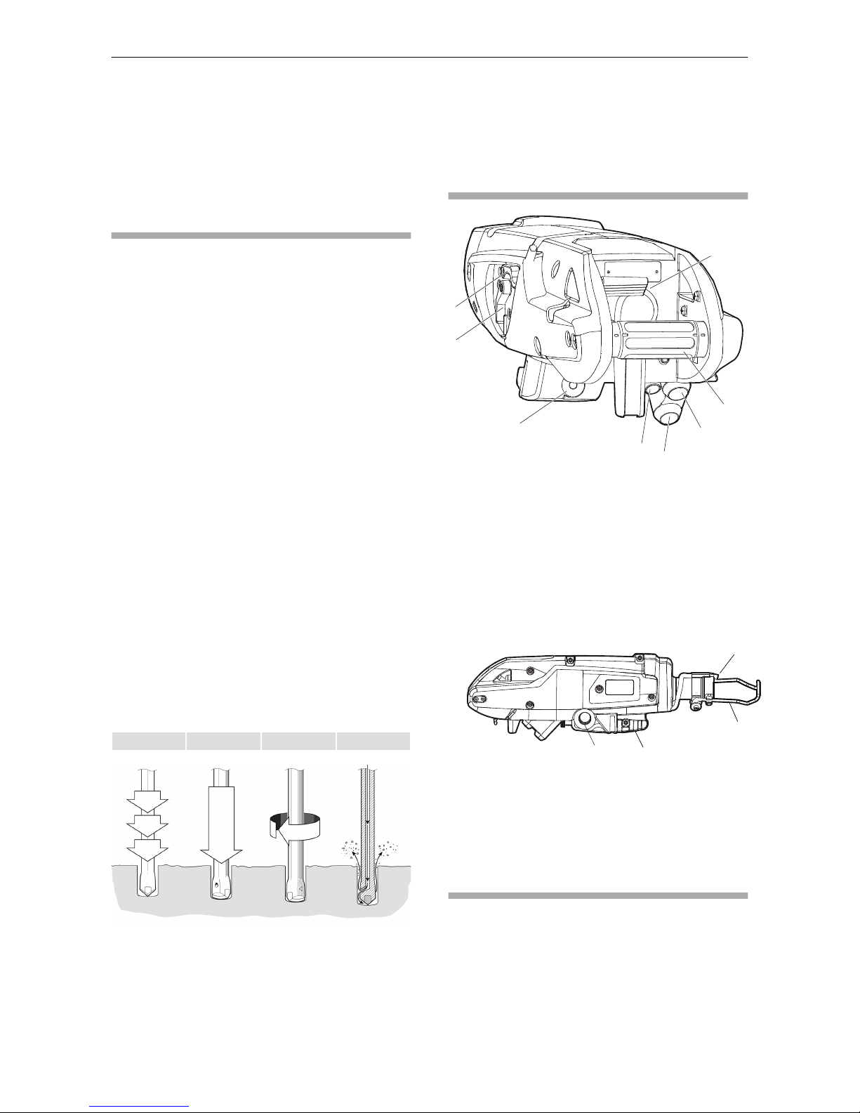
Working principle of a rock drill
Impact Feed force Rotation Flushing
Water flushing
Water flushing is ducted through the anvil to the
drilling steel. The water flushing engages as soon
as the rock drill is turned on. It is also possible to
manually adjust the water flushing with a lever.
Use of water flushing has also a reducing effect of
dust and fumes.
The water hose is connected via the power pack to
the rock drill and the pusher leg.
Main parts
A
B
C
D
E
F
G
H
A. Manually water flushing
B. Water flushing adjust
C. Pusher leg locking lever
D. Throttle lever
E. Water inlet
F. Oil return line
G. Oil pressure line
H. Twist handle, feed control lever
IJ
K
L
I. Machine attachment
J. Front support handle
K. Outlet water from the pusher leg
L. Drill steel retainer
Labels
The machine is fitted with labels containing
important information about personal safety and
machine maintenance. The labels must be in such
condition that they are easy to read. New labels
can be ordered from the spare parts list.
Safety and operating instructions RD 100
12 © Construction Tools PC AB | 9800 1365 01 | 2018-01-01
Original instructions
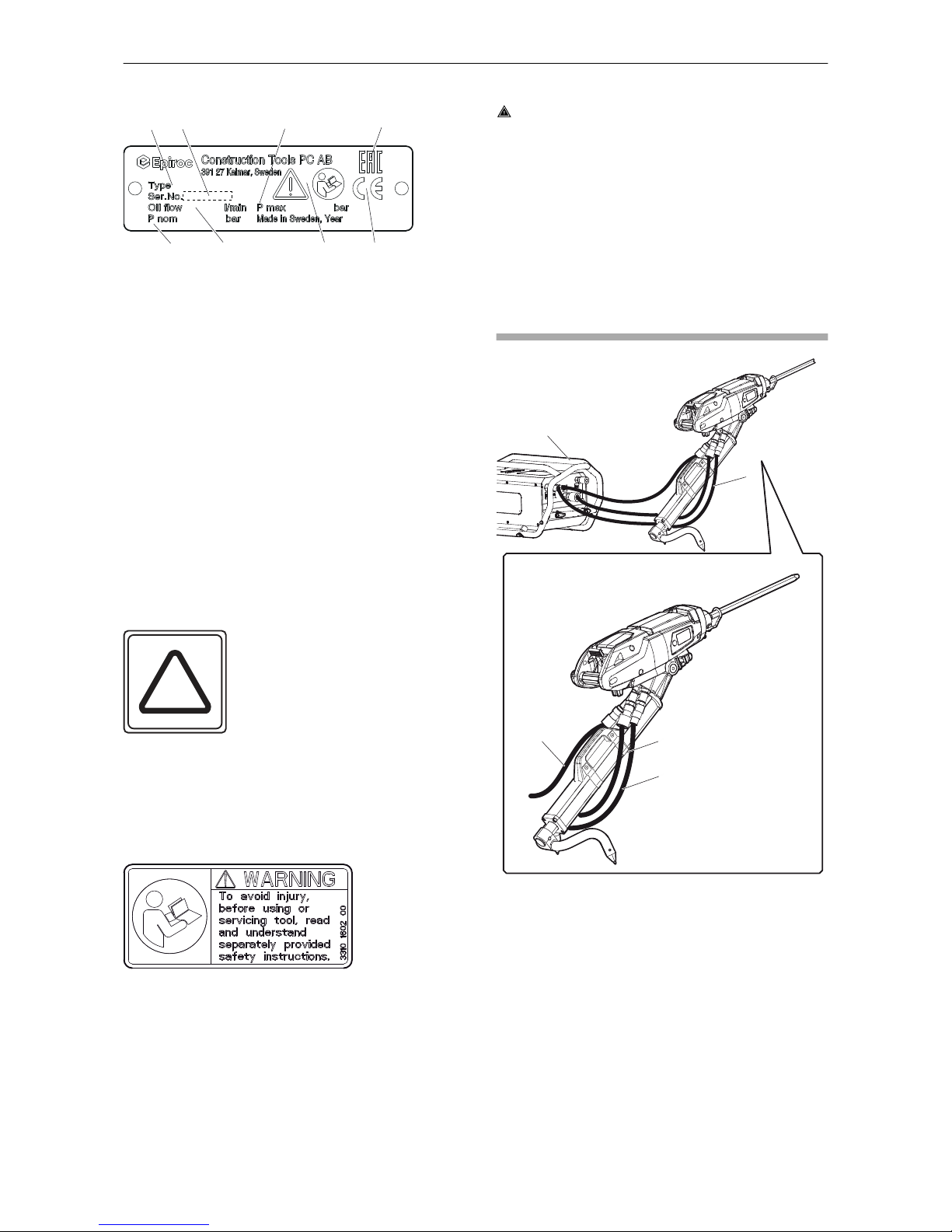
Data plate
ABC
DEFG
H
A. Machine type
B. Serial number
C. Maximum permitted hydraulic pressure
D. Maximum nominal operating pressure
E. Oil consumption
F. The warning symbol together with the book
symbol means that the user must read the
safety and operating instructions before the
machine is used for the first time.
G. The CE symbol means that the machine is EC-
approved. See the EC declaration which is
delivered with the machine for more
information. If the CE symbol is missing, it
means that the machine is not EC-approved.
H. The EAC symbol means that the machine is
EAC approved.
Labels on the accumulator
2
N
The accumulator must only be charged with
Nitrogen.
NOTICE Only certified personnel are allowed to
work with the accumulator.
Safety label
To avoid injury, before using or servicing tool, read
and understand separately provided safety
instructions.
Installation
WARNING Whipping hose
Hoses under pressure can whip uncontrollably if
the hose connection becomes loose. A whipping
hose can cause severe injuries. To reduce this risk:
►Turn of the power pack before loosening the
connection of a hose.
►Check that the hose and the connections are
not damaged.
►Never carry or drag the machine by the hoses.
Hoses and connections
CD
E
A
B
A. Power pack, PP 100.
B. Maximum 10 meter (33 ft) hydraulic hose
between the power pack and the rock drill.
C. Water hose connected to the power pack.
D. Oil pressure line.
E. Oil return line.
◆Check that the correct recommended operating
pressure is used, 120 bar (1,740 psi).
◆Wipe all couplings clean before connecting to
the machine.
◆Check that the rock drill is in stop mode before
starting the power pack.
RD 100 Safety and operating instructions
© Construction Tools PC AB | 9800 1365 01 | 2018-01-01
Original instructions
13

Hoses
The hydraulic hose must be approved for a
working pressure of at least 240 bar (3,480 psi), for
connection to the machine.
Choose the correct dimension and length for the
hydraulic hose. For hose lengths up to 10 meters,
a hose with a minimum internal diameter of 16 mm
(5⁄8 in.) must be used. To choose the correct hose,
see the spare parts list.
To resist exterior wear and tear, we recommend
using a 2-layer hydraulic hose. The machine
connection marked P (pump) is the oil inlet, and
the connection marked T (tank) is the oil outlet.
Always fill up the hydraulic hoses with oil and
circulate it before connecting the rock drill. Use a
pump to circulate the oil, see the spare parts list.
Connect both hoses and make sure that all hose
connections are tight. Never carry the machine by
the hose.
NOTICE Attach the return line hose and the
pressure line hose according to matching colors.
The red color is for the pressure line, the blue color
is for the return line.
Quick-release couplings
The original hydraulic hoses are fitted with Flat-
Face quick-release couplings that are strong and
easy to clean. The quick-release couplings are
fitted so that the male connection supplies oil and
the female connection receives oil.
NOTICE Wipe all couplings clean before
connecting. Ensure that couplings are clean and
correctly engaged before operation. Failure to do
so may result in damage to the quick couplings
and cause overheating and cause foreign matter to
enter the hydraulic system.
Hydraulic oil
In order to protect the environment, use of
biologically degradable and flame proof hydraulic
oil (HFD-U) is recommended. No other fluids must
be used.
◆Viscosity (preferred) 40-60 cSt. at working
temperature.
Make sure to only use clean oil and filling
equipment.
When the machine is used continuously, the oil
temperature will stabilise at a level which is called
the working temperature. This will, depending on
the type of work and the cooling capacity of the
hydraulic system, be between 20-40°C (68-104°F)
above the ambient temperature. At working
temperature, the oil viscosity must be within the
preferred limits. The viscosity index indicates the
connection between viscosity and temperature. A
high viscosity is therefore preferred, because the
oil can then be used within a wider temperature
range. The machine must not be used, if oil
viscosity fails to remain within the permitted area,
or if the working temperature of the oil does not fall
between 20°C (68°F) and 70°C (158°F).
Methods to prevent freezing
If the rock drill freeze, never heat it to melt the ice.
Always let the ice melt at room temperature.
Never pour methylated spirits or similar substances
into the rock drill, as they will interfere with the
lubrication and lead to increased wear.
If the temperature is below 0 °C, blow out the
water hose with compressed air before storage to
avoid frost expansion.
NOTICE Maximum allowable air pressure is 7
Bar.
Pressure adjustment
Hydraulic oil pressure
The hydraulic oil pressure is regulated by the PP
100. Ensure that it can deliver the required oil
pressure of 100-120 bar (1,450 – 1,740 psi) to the
machine.
◆Too high pressure causes rough operation and
excessive wear.
◆Too low pressure results in a slow drilling
speed.
Water pressure
The water pressure is regulated by the PP 100.
The incoming pressure to the PP 100 must be
between 5-13 bar (73-189 psi) at a flow rate of 12
l.p.m (2.6 UK gal/min) to obtain good water
flushing and good functionality on the pusher leg.
Drill steel
WARNING Running power pack
Changing the drill steel or accessories while the
power pack is running can cause serious injury.
►Shut off the power pack and disconnect the
hydraulic hoses during mounting or dismounting
of the drill steel.
Safety and operating instructions RD 100
14 © Construction Tools PC AB | 9800 1365 01 | 2018-01-01
Original instructions

►Secure the power pack against involuntary
activation.
Before fitting the drill steel
Check that the tool shank is of the correct size and
length for the chuck used. The tool shank must be
clean and the drill steel must be in good condition.
Tool shanks which are chipped, rounded, out of
square, or too hard on the striking end will operate
inefficiently and cause premature piston failure.
Inspect the drill steel:
A dull drill steel will slow down the drilling speed
and overstrain the drill mechanism. When
changing drill steel make sure that the new one is
of the correct size to follow the previous bore.
Before drilling, check that the flushing hole in the
drill steel is not blocked.
WARNING Ejected drill steel
If the tool retainer on the machine is not in a locked
position, the drill steel can be ejected with force,
which can cause personal injury.
►Never start the machine while changing the drill
steel.
►Before changing the drill steel or accessories,
stop the machine and turn off the power source.
►Never point the drill steel at yourself or anyone
else.
►Make sure that the drill steel is fully inserted
and the tool retainer is in a locked position
before the machine is started.
►Check the locking function by pulling the drill
steel outwards forcefully.
WARNING Vibration hazard
Using inserted tools that do not fulfil the criteria
mentioned below, will result in a longer time to
complete a task, and may result in higher levels of
vibration exposure. A worn tool will also cause
increased working time.
►Make sure that the inserted tool is well-
maintained, not worn out and of the proper size.
►Always use a sharp tool in order to work
efficiently.
WARNING Injured hands
There is a risk of crushing fingers when changing
the drill steel. To recuce this risk:
►Never inspect, clean, install, or remove the
working tool while the power source is
connected.
►Never put the fingers between the drill steel
retainer and the chuck.
CAUTION Hot drill steel
The tip of the drill steel can become hot and sharp
when used. Touching it can lead to burns and cuts.
►Never touch a hot or sharp drill steel.
►Wait until the drill steel has cooled down before
carrying out maintenance work.
NOTICE Never cool a hot insertion tool in water,
it can result in brittleness and early failure.
Changing drill steel
Whenever changing a drill steel the following
instructions must be observed. Also, make sure
that the tool retainer is of the proper size.
1. When removing the drill steel. Push the tool
retainer outwards, ensure that the tool retainer
is fully up.
2. Insert the drill steel in the chuck.
RD 100 Safety and operating instructions
© Construction Tools PC AB | 9800 1365 01 | 2018-01-01
Original instructions
15
3. When the drill steel bottoms, push back the tool
retainer to lock it.
Operation
WARNING Involuntary start
Involuntary start of the machine may cause injury.
►Keep your hands away from the start and stop
device until you are ready to start the machine.
►Learn how the machine is switched off in the
event of an emergency.
►Stop the machine immediately in all cases of
power supply interruption.
Preparations before starting
Check the drilling equipment
The following checks must be made before start
using the rock drill. All these checks concern the
serviceability of the rock drill. Some concerns
safety:
◆Clean all labels. Replace any that are missing
or cannot be read.
◆Inspect the hoses generally for signs of
damage.
◆Inspect the drill steel and drill bit for wear and
damage. Do not use an excessively worn or
damaged drill steel.
◆Inspect the tool retainer for wear and function.
◆Close the tool retainer.
◆Check that the flushing holes in the drill steel
and drill bit are not blocked, and that the
flushing water flows through without
obstruction.
◆The drill steels must be from the same ISO-
series, if different lengths are used in the same
drill hole.
◆Remove the protective caps from the
quickrelease couplings.
◆Ensure that the hydraulic couplings are clean
and fully serviceable.
◆Ensure that the hydraulic hoses are filled with
oil.
◆Connect the machine.
◆Ensure that any power source that are planned
to use is compatible with the rock drill, see
section "Technical data".
◆Check that the rock drill is in stop mode before
starting the power source.
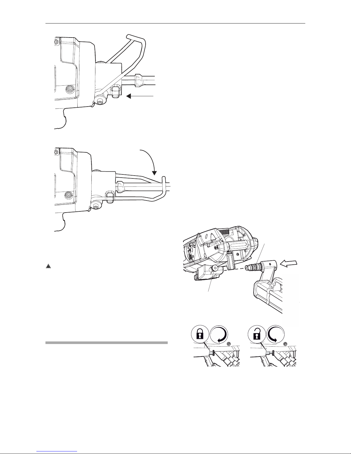
Attaching pusher leg to rock drill
A
B
1. Make sure that the pin (A) and the machine
attachment are clean.
2. Pull out the locking lever (B) and turn
counterclockwise to lock it in the open position.
3. Mount the pusher leg to the rock drill.
Safety and operating instructions RD 100
16 © Construction Tools PC AB | 9800 1365 01 | 2018-01-01
Original instructions
4. Turn the locking lever (B) clockwise to secure
the pusher leg. Make sure that the lever gets
pushed all the way in.
5. Fill the pusher leg with water by extracting and
retracting it a few times.
Controls
Water flushing lever
A
B
+
-1
0
The rock drill is equipped with throttle levers for
regulating the water flushing.
A. Water flushing adjust.
B. Manual water flushing.
Throttle lever
A
A
Adjust the throttle by using the throttle lever as
follows:
1. Pull the throttle lever (A) to start and increase
the throttle.
2. Press the throttle lever (A) to decrease the
throttle and for stopping the machine.
Twist handle
B
C
A
Adjust the pusher leg by using the twist handle as
follows:
1. Make sure that the twist handle is in neutral
position (A) when starting the power pack.
2. Turn the twist handle backwards (B) to extract
the pusher leg.
3. Turn the twist handle forwards (C) to retract the
pusher leg.
Start and stop
Drilling
◆Use protective shoes, gloves, helmet, ear
protectors and impact resistant eye protection
with side protection.
◆Stand firmly and always hold the machine with
both hands. Hold one hand on the twist handle
(A) and the other on the front support handle
(C).
◆Hold the inserted tool firmly against the work
surface before starting the machine.
RD 100 Safety and operating instructions
© Construction Tools PC AB | 9800 1365 01 | 2018-01-01
Original instructions
17
Starting the rock drill
B
AC
1. Check that the drill steel and drill bit are in good
condition and properly attached to the rock drill.
2. Check that the tool retainer is locked, so that
the drill steel does not fall out.
3. Start the power source.
4. Adjust the twist handle (A) to give a suitable
feed force for collaring the hole.
5. Align the rock drill so that the drill steel touches
the required collaring point. Avoid small
irregularities on the surface, since they break
easily and cause either a wrong working angle
or blank firing.
6. Move the throttle lever (B) forward a little,
which starts the water flushing, the percussion
and rotation.
7. Press the rock drill firmly against the material to
be drilled. Turn the twist handle to push the
rock drill forward by means of the pusher leg.
Increase to full throttle when collaring is under
control.
8. Adjust the feed force to ensure that the rock
drill runs regularly.
Stopping the rock drill
B
AC
◆Pull the throttle lever (B) backwards. This stops
the percussion, rotation, and flushing water.
Operating
Re-position of the pusher leg
B
A
B
A
1. Switch off the rock drill percussion, rotation and
flushing by means of the throttle lever (B).
Safety and operating instructions RD 100
18 © Construction Tools PC AB | 9800 1365 01 | 2018-01-01
Original instructions

2. Retract the pusher leg, by turning the twist
handle (A).
3. Re-position the pusher leg. Ensure that the
pusher leg stands securely on the gound.
4. Follow the start procedures , see section
"Starting the rock drill".
Flush-cleaning the drill hole
If flush-cleaning of the drill hole is required:
1. Start the manual water flushing, see section
"Water flushing lever".
2. When the drill hole is clean, push the throttle
lever forwards again to re-start the rock drill.
When taking a break
◆Place the machine in such a way that there is
no risk for it to be unintentionally started. Make
sure to place the machine on the ground, so
that it can not fall.
◆In the event of a longer break or when leaving
the workplace: Switch off the power source and
shut off the incoming water supply.
Maintenance
Regular maintenance is a basic requirement for
the continued safe and efficient use of the
machine. Follow the maintenance instructions
carefully.
◆Before starting maintenance on the machine,
clean it in order to avoid exposure to hazardous
substances. See “Dust and fume hazard”.
◆Use only authorised parts. Any damage or
malfunction caused by the use of unauthorised
parts is not covered by warranty or product
liability.
◆When cleaning mechanical parts with solvent,
comply with appropriate health and safety
regulations and ensure there is satisfactory
ventilation.
◆For major service of the machine, contact the
nearest authorised workshop.
◆After each service, check that the machine's
vibration level is normal. If not, contact the
nearest authorised workshop.
◆Use the right type, and amount of greases and
oils.
Every day
Before undertaking any maintenance or changing
the drill steel on rock drills, always turn off and
disconnnect the power source.
◆Clean and inspect the drilling equipment and its
functions each day before start working.
◆Check the tool retainer and bushing for wear
and function.
◆Conduct a general inspection for leaks,
damage, and wear.
◆Make sure that all the attached and related
equipment, such as hoses and couplings are
properly maintained.
◆Check the function of the throttle lever. Make
sure that it moves freely up and down.
◆Check the covers for wear and function.
◆Change damaged parts immediately.
◆Replace worn components in good time.
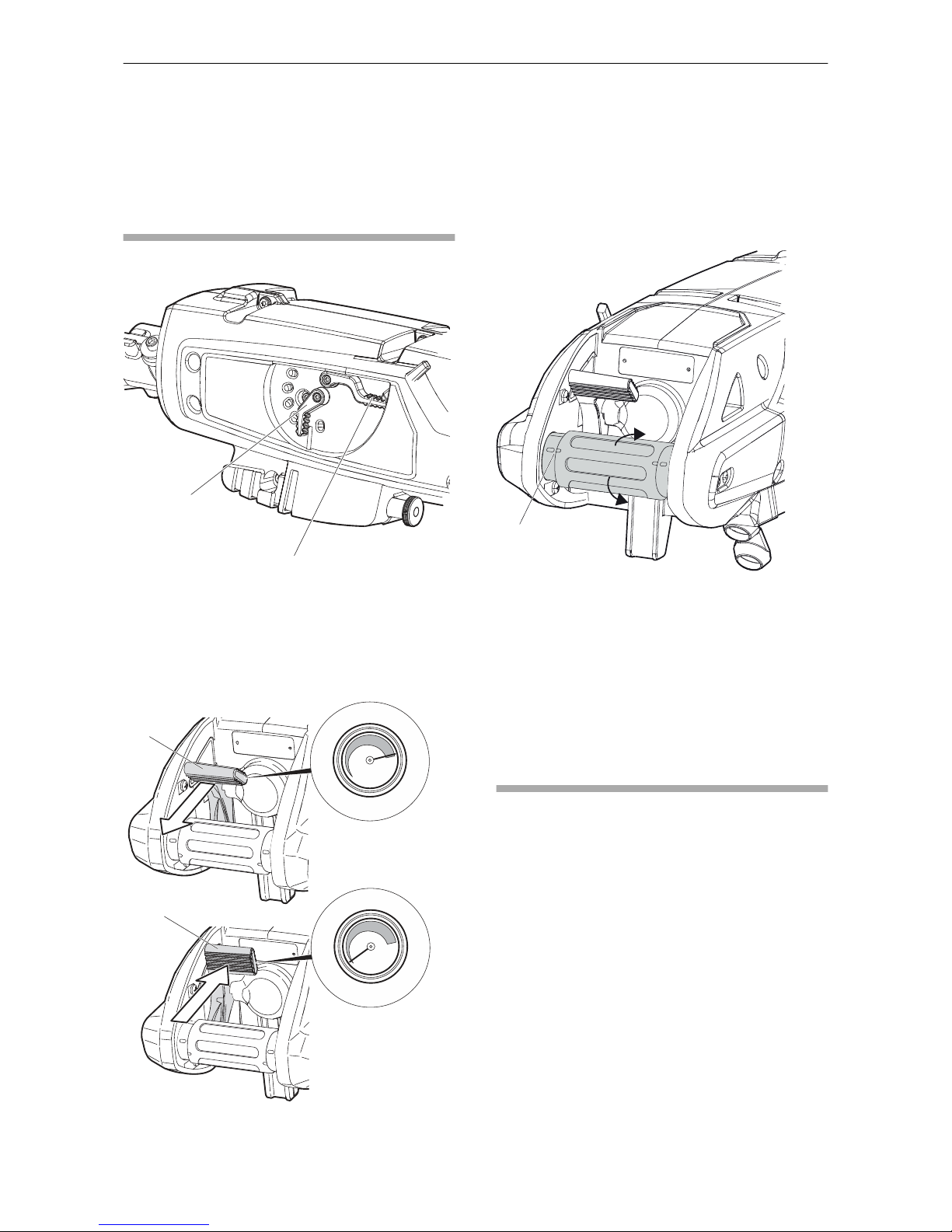
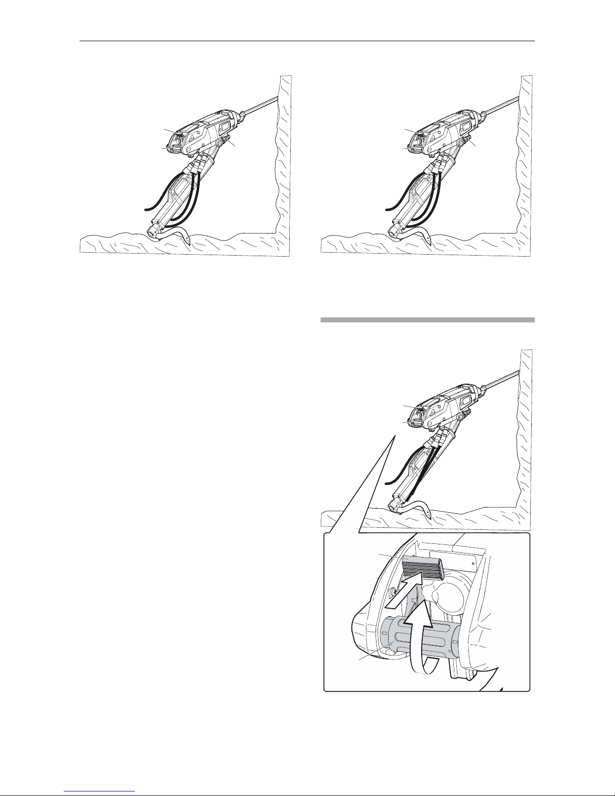
Checking for wear
Check the wear in the drill bushings using the
Epiroc gauge (part number 3121 5690 00). Insert
the gauge diagonally. To check the wear, twist the
gauge. If the wear gauge can be rotated the
bushings needs to be replaced. Check wear in
both the inner and outer bushings at the
highlighted positions in the image below. The wear
will be largest at these positions.
If the wear limit has been exceeded, the drill steel
shank will wear more quickly, or become deformed.
This will lead to stoppages and increased drill-steel
consumption. There is also a risk for high stresses
on the rockdrill and possible breakdown due to
miss alignment between the drill chuck and the drill
steel.
RD 100 Safety and operating instructions
© Construction Tools PC AB | 9800 1365 01 | 2018-01-01
Original instructions
19
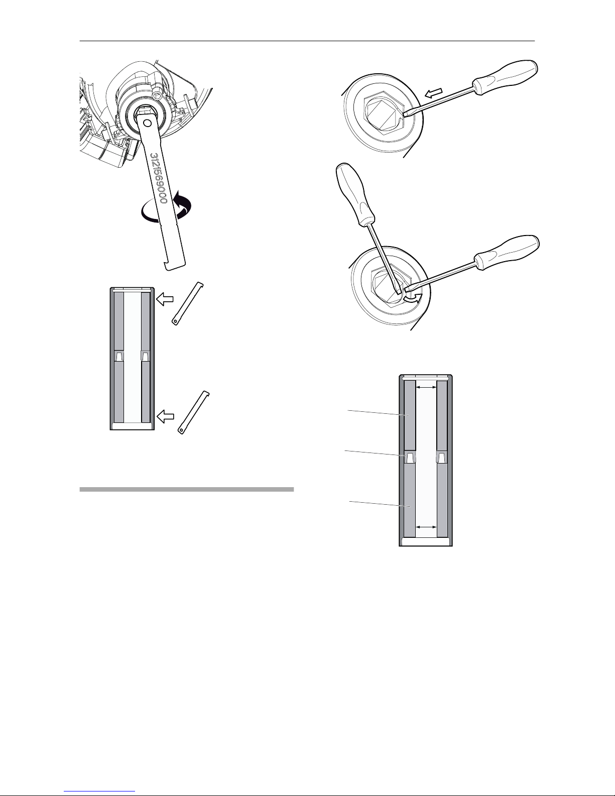
Replace the drill steel
bushings
The bushings must be replaced if they show signs
of wear.
1. Remove the lock ring from the front of the
RD100. Use a wide flat-head screwdriver and
put it into the groove and gently turn it so it is
possible to lift the lock ring from the groove.
Insert another screw driver under the ring and
lift it out from the groove. The lock ring must be
replaced together with the bushings.
2. Use the Epiroc wear gauge to remove the outer
bushing (A) sealing ring (B) and inner bushing
(C).
A
B
C
3. Insert the the wear gauge in one of the
bushings corners and push it in against the
anvil so the hook grabs at the inner edge of the
bushing. Slightly twist the tool so it grabs the
flat area were it will get best grip. Use a screw
driver as a handle and pull both bushings and
seal out.
Safety and operating instructions RD 100
20 © Construction Tools PC AB | 9800 1365 01 | 2018-01-01
Original instructions
Other manuals for RD 100
1
Table of contents
Other Epiroc Drill manuals


