EpiSensor ZDR-10 User manual

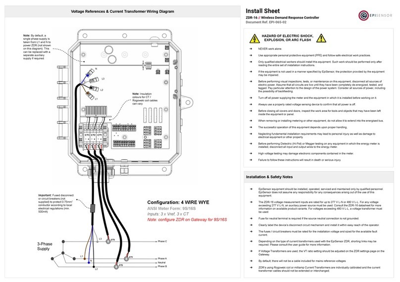
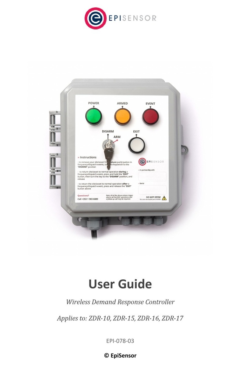
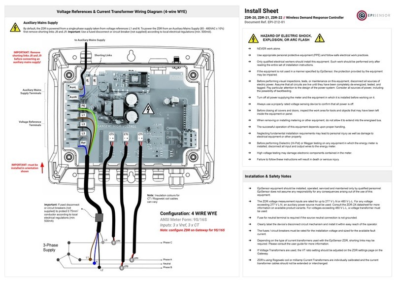
User Guide
Wireless Demand Response Controller
Applies to: ZDR-10, ZDR-15, ZDR-16
EPI-078-02
© EpiSensor

Table of Contents
Safety Information 4
Electrical Installation 4
Intended Use 6
Related Documents 6
Introduction 7
Benefits 7
Features 7
Data Feeds & Settings 8
Frequency Response Settings 8
Meter Configuration, Property 6036 9
System State Sensors 9
Event Response Sensors 9
User Interface Sensors 10
Electricity Metering Sensors 10
Analogue & Digital Inputs 12
Frequency Response Specification 12
Reaction Time 13
User Interface 13
Status LED 13
Mode Button 14
Install Mode 15
Front Panel 15
Demand Response Logic 16
Rules Engine 17
Remote Management 17
Gateway API 17
Page 2
of 37

Firmware Updates 18
Hardware Features 18
Power Supply 20
Communications 21
Wireless Communications 22
Electricity Metering 23
Electricity Metering 23
Current Transformers 23
Rogowski Coils 24
Supported 3-phase configurations 25
Voltage Reference 26
Switch Output 27
Analogue Inputs 27
Digital Inputs 28
Pulse Info 28
Pulse Operation 29
Dry Pulse 29
Open Collector Pulse 29
Active Pulse 30
Mechanical 30
Enclosure & Label Material 30
Mounting Instructions 30
Opening the Enclosure 31
Tamper Evident Seals 32
Compliance Label 33
Ordering Information 35
Troubleshooting & Support 36
Warranty 36
Glossary 36
Page 3
of 37

Safety Information
Please read these instructions carefully before trying to install, operate, service or maintain the ZDR. The
following special notes may appear throughout the user guide (or on the equipment labels) to warn of potential
hazards or to call attention information that clarifies or simplifies a procedure for users.
Symbol
Description
The addition of either symbol to a “Danger” or “Warning” safety label indicates that an
electrical hazard exists which will result in personal injury if the instructions are not
followed.
This is the safety alert symbol. It is used to alert you to potential personal injury hazards.
Obey all safety messages that follow this symbol to avoid possible injury or death.
This symbol notes that Electrostatic discharge (ESD) events can harm electronic components
inside this product. Protect against ESD and discharge static electricity from your body
before you interact with this product.
Electrical Installation
Electrical equipment should be installed, operated, serviced and maintained only by qualified personnel. No
responsibility is assumed by EpiSensor for any consequences arising out of the use of this material.
A qualified person is one who has skills and knowledge related to the construction, installation, and operation of
electrical equipment and has received safety training to recognize and avoid the hazards involved.
Installation, wiring, testing and service must be performed in accordance with all local and national electrical
codes.
HAZARD OF ELECTRIC SHOCK, EXPLOSION, OR ARC FLASH
➔NEVER work alone.
➔Use appropriate personal protective equipment (PPE) and follow safe electrical work practices.
➔Only qualified electrical workers should install this equipment. Such work should be performed only
after reading the entire set of installation instructions.
Page 4
of 37

➔If the equipment is not used in a manner specified by EpiSensor, the protection provided by the
equipment may be impaired.
➔Before performing visual inspections, tests, or maintenance on this equipment, disconnect all sources
of electric power. Assume that all circuits are live until they have been completely de-energized,
tested, and tagged. Pay particular attention to the design of the power system. Consider all sources of
power, including the possibility of backfeeding.
➔Turn off all power supplying the meter and the equipment in which it is installed before working on it.
➔Always use a properly rated voltage sensing device to confirm that all power is off.
➔Before closing all covers and doors, inspect the work area for tools and objects that may have been
left inside the equipment or panel.
➔When removing or installing metering or other equipment, do not allow it to extend into the
energised bus.
➔The successful operation of this equipment depends upon proper handling,
➔Neglecting fundamental installation requirements may lead to personal injury as well as damage to
electrical equipment or other property.
➔Before performing Dielectric (Hi-Pot) or Megger testing on any equipment in which the energy meter
is installed, disconnect all input and output wires to the energy meter.
➔High voltage testing may damage electronic components contained in the meter.
➔Failure to follow these instructions will result in death or serious injury.
Installation & Safety Notes
➔EpiSensor equipment should be installed, operated, serviced and maintained only by qualified
personnel. EpiSensor does not assume any responsibility for any consequences arising out of the use
of this equipment.
➔The ZDR voltage measurement inputs are rated for up to 250 V L-N or 433 V L-L. For any voltage
exceeding 250 V L-N, an auxiliary power source must be used. Consult the ZDR datasheet for more
information on available product variants. For voltages exceeding 433 V L-L, a voltage transformer
must be used.
Page 5
of 37

➔Fuse for neutral terminal is required if the source neutral connection is not grounded.
➔Clearly label the device’s disconnect circuit mechanism and install it within easy reach of the operator.
➔The fuses / circuit breakers must be rated for the installation voltage and sized for the available fault
current.
➔If Voltage Transformers are used, the power consumption values must be adjusted in ZDR settings
accordingly.
➔Each ZDR meter is individually calibrated and the current transformer cables should not be extended
or interchanged.
Intended Use
Do not use this device for critical control or protection applications where human or equipment safety relies on
the operation of the control circuit. Failure to follow these instructions can result in death, serious injury, or
equipment damage.
Related Documents
Related installation and configuration documents are listed in the following table:
Document
Reference No.
EpiSensor ZDR Datasheet
EPI-066-00
Install Sheet for ZDR
EPI-065-00
Gateway API User Guide
ESE-009-08
Bootloading on a live Gateway
EPI-064-00
Configuring the High Speed Data Module on ZDR
EPI-131-02
Application Note - Demand Response Event Data
EPI-124-01
Page 6
of 37

Introduction
EpiSensor’s ZDR enables customers to participate in multiple Demand and Frequency response programs. It
includes best-in-class functionality to accurately monitor electrical load (via CT’s or pulse inputs), frequency and
can take action to shed load or engage backup generators based on frequency set points or commands sent
from a remote network operations centre.
The system is capable of streaming data securely to a Network Operations Centre (NOC) to arm the system,
detect low frequency events, override the system remotely, and switch loads both automatically and manually.
With a wide range of additional sensors available, EpiSensor’s platform can also be used for energy
management, environmental monitoring and many other applications.
This guide discusses features of the EpiSensor ZDR series demand response controller and provides installation
and configuration instructions.
For the most up-to-date version of this document and others, please visit www.episensor.com
Benefits
●Significantly lower cost and physical size than other solutions
●Can be expanded to multiple ‘apps’ with additional sensors available
●Multiple ZDR’s can communicate to a single Gateway
Features
●4 relays for asset control
●2-channel high frequency pulse inputs
●2-channel 4-20mA analog inputs
●100ms reaction time for under frequency events
●Live stream (1-second) data for 3-phase power consumption, current and frequency
●Modbus (RS-485) communications capability
Page 7
of 37

Data Feeds & Settings
The list of parameters that are available to monitor on the ZDR are listed below. Data reporting can be enabled
or disabled as required for each of the ‘sensors’ below.
Frequency Response Settings
The following table lists the settings on the ZDR that related to frequency response. They define how the ZDR
should respond to under-frequency events and how the current state of the hardware. These items are
configured as properties on the ZDR rather than sensors.
Property ID
Setting
Description
Unit
Resolution
Reporting
Default
Read/Write
6500
Event Sensor
The sensor ID for which the system
is monitoring to generate events.
Initially this is only configurable for
“none” indicating no events are
generated locally, or “Line
Frequency - 342” for frequency
monitoring.
-
-
-
none
Read/Write
6501
Enter Event Value
The value at which the system will
trigger the start of an event.
Raw Sensor
Units
1
-
49700
Read/Write
6502
Exit Event Value
The value at which the system will
exit the event.
Raw Sensor
Units
1
-
49800
Read/Write
6503
Auto Exit
Defines whether the site will exit a
trip state automatically after an
event, or if it should waits for a ‘soft
reset’ from a user via the
pushbutton.
TRUE
/FALSE
1
-
0
Read/Write
6504
Minimum Event
Time
The minimum amount of time the
unit must remain in an event.
Sec
1
-
0
Read/Write
6505
Event Reset Time
After an event, this is the minimum
amount of time the unit must
remain in the non-event state before
another event will trigger
Sec
1
-
0
Read/Write
6550
CT Ratio
A multiplier on the CT input channel
which is applied to the calibration
constants within the metering
section of the ZDR System. It allows
for 100:1 or 100:5 (20:1) type Ratios
to be applied to the CTs
-
-
-
1
Read/Write
6551
VT Ratio
A multiplier on the VT input channel
which is applied to the calibration
constants within the metering
section of the ZDR System. It allows
the ZDR be connected to MV
systems with (for example) 11kV
inputs using VTs that output 110V.
-
-
-
1
Read/Write
6036
Configuration
The American ANSI C12.10 standard
defines the different configurations
of the meter. This defines how the
active power accumulated in each
watt-hour register is calculated.
-
-
-
9S/16S
4-wire
Wye
Read/Write
Page 8
of 37

Meter Configuration, Property 6036
The active power accumulated in each watt-hour sensor depends on the configuration of the Meter. Choose the
appropriate value from the table below depending on how the ZDR is connected to a 3-phase system. This is
based on the ANSI C12.10 standard.
Ansi Meter Form
Configuration
Phase A Watt Hours
Phase B Watt Hours
Phase C Watt Hours
9S/16S
4-wire wye
VA x IA
VB x IB
VC x IC
5S/13S
3-wire delta
VA x IA
0
VC x IC
6S/14S
4-wire wye
VA x IA
VB × IB
Where VB = −VA − VC
VC x IC
8S/15S
4-wire delta
VA x IA
VB × IB
Where VB = −VA
VC x IC
System State Sensors
These sensors provide data on the state of the ZDR State Variables and can be used to trigger state changes at
the NOC or for audit/compliance purposes.
Sensor ID
Data Feed
Description
Unit
Resolution
Reporting
Default
Read/Writ
e
24
Armed
Set to 1 when the Key Switch is in
the Armed position AND the ZDR
system is actively monitoring an
Event Sensor. Set to 0 otherwise.
1/0
1
Interval
and Delta
-
Read Only
25
Opt Out
Set to 1 when the Gateway or API
removes a device from an active
event with the Opt Out command
OR when a user on site has removed
the site from an event by the Opt
Out key sequence on the front panel
- Press and hold the Exit button and
turn the key switch to Disarm.
1/0
1
Interval
and Delta
-
Read Only
Event Response Sensors
The following sensors produce data on the state of the ZDR showing whether an event is currently in progress,
or if the ZDR has been triggered remotely by the NOC.
Sensor ID
Data Feed
Description
Unit
Resolution
Reporting
Default
Read/Writ
e
27
Event Response
Notifies that an event is currently in
progress. Will be reset if a user takes
the site out of trip with the
pushbutton and keylock, or with
1/0
1
Interval
and Delta
-
Read Only
Page 9
of 37

remote override. Or if the event
ends and the system is configured to
Auto Exit
26
Demand Response
Notifies that a demand response
event is currently in progress. Will be
reset either by the manual override
push button, or remote override. Or
if the event ends and the system is
configured to Auto Exit
1/0
1
Interval
and Delta
-
Read Only
359
Switch
The position of the switch. Writing 1
to the switch initiates a DR Event,
while writing 0 to the switch ends a
DR Event. Note that the switch could
be ON, when no event is in progress
if the system is waiting for a manual
Exit.
1/0
1
Interval
and Delta
-
Read/Write
User Interface Sensors
These sensors provide data on the state of the user interface and can be used to trigger state changes at the
NOC or for audit/compliance purposes.
Sensor ID
Data Feed
Description
Unit
Resolution
Reporting
Default
Read/Writ
e
41
Key Switch
The position of the key switch. 1 =
Armed, 0 = Not Armed
-
1
Interval
and Delta
-
Read Only
42
Exit Button
The position of the Exit Button, 1 =
pressed, 0 = released
-
1
Interval
and Delta
-
Read Only
250
Enter Event Value
An Echo of the Enter Event Value
Property 6501 which allows this to
be exported as a Sensor in the
normal fashion
-
1
Snap to
Clock
-
Read Only
251
Exit Event Value
An Echo of the Exit Event Value
Property 6502 which allows this to
be exported as a Sensor in the
normal fashion
-
1
Snap to
Clock
-
Read Only
Electricity Metering Sensors
These read-only ‘sensors’ provide data on the power consumption and frequency of the 3-phase system that the
ZDR is monitoring.
Sensor ID
Data Feed
Description
Unit
Resolution
Reporting
Default
Read/Writ
e
300
Phase A kWh
Phase A kWh value. This is a
continually increasing kWh reading.
kWh
0.01
Off
-
Read/Write
301
Phase B kWh
Phase B kWh value. This is a
continually increasing kWh reading.
kWh
0.01
Off
-
Read/Write
Page 10
of 37

302
Phase C kWh
Phase C kWh value. This is a
continually increasing kWh reading.
kWh
0.01
Off
-
Read/Write
303
Phase A RMS
Current
Instantaneous Phase A RMS Current.
A
0.1
Off
-
Read Only
304
Phase B RMS
Current
Instantaneous Phase B RMS Current.
A
0.1
Off
-
Read Only
305
Phase C RMS
Current
Instantaneous Phase C RMS Current.
A
0.1
Off
-
Read Only
306
Phase A RMS
Voltage
Instantaneous Phase A RMS Voltage.
V
0.1
Off
-
Read Only
307
Phase B RMS
Voltage
Instantaneous Phase B RMS Voltage.
V
0.1
Off
-
Read Only
308
Phase C RMS
Voltage
Instantaneous Phase C RMS Voltage.
V
0.1
Off
-
Read Only
324
Phase A Active
Power
Instantaneous Active Power on
Phase A
W
1
Off
-
Read Only
325
Phase B Active
Power
Instantaneous Active Power on
Phase B
W
1
Off
-
Read Only
326
Phase C Active
Power
Instantaneous Active Power on
Phase C
W
1
Off
-
Read Only
330
Phase A Power
Factor
Power Factor on Phase A
%
1%
Off
-
Read Only
331
Phase B Power
Factor
Power Factor on Phase B
%
1%
Off
-
Read Only
332
Phase C Power
Factor
Power Factor on Phase C
%
1%
Off
-
Read Only
333
Total kWh
The sum of Phase A, B and C kWh,
sensors 300, 301 and 302
kWh
0.1
Off
-
Read/Write
335
Total Active Power
The instantaneous sum of Phase A, B
and C Active Power, sensors 324,
325 and 326
KW
0.001
Off
-
Read Only
338
Interval Phase A
kWh
The kWh on Phase A since the
previous data point.
kWh
0.01
Off
-
Read/Write
339
Interval Phase B
kWh
The kWh on Phase A since the
previous data point.
kWh
0.01
Off
-
Read/Write
340
Interval Phase C
kWh
The kWh on Phase A since the
previous data point.
kWh
0.01
Off
-
Read/Write
341
Interval Total kWh
The total kWh on all phases since
the previous data point.
kWh
0.1
Off
-
Read/Write
342
Line Frequency
The Line Frequency of the 3 Phase
system. This is read from the Phase
A voltage channel
Hz
0.001
Live
Stream
-
Read Only
Page 11
of 37

Analogue & Digital Inputs
These data feeds show the number of pulses counted by the ZDR and average 4-20mA analogue input readings.
Sensor ID
Data Feed
Description
Unit
Resolution
Reporting
Default
Read/Writ
e
394
4-20 MilliAmps
Now 1
The Instantaneous Milli Amp value
on channel 1 of the 4-20 Milliamp
input.
mA
0.001
Off
-
Read Only
396
4-20 MilliAmps
MIn 1
The number of pulses recorded on
channel 2 during the previous
reporting interval.
Ma
0.001
Off
-
Read Only
397
4-20 MilliAmps
Max 1
The average 4-20mA value of
channel 1.
mA
0.001
Off
-
Read Only
494
4-20 MilliAmps
Now 2
The Instantaneous Milli Amp value
on channel 1 of the 4-20 Milliamp
input.
mA
0.001
Off
-
Read Only
496
4-20 MilliAmps
MIn 2
The number of pulses recorded on
channel 2 during the previous
reporting interval.
Ma
0.001
Off
-
Read Only
497
4-20 MilliAmps
Max 2
The average 4-20mA value of
channel 1.
mA
0.001
Off
-
Read Only
450
Pulse Count
The total Pulse Count on Channel 1
of the Pulse Input
pulses
1
Off
-
Read/Write
462
Interval Pulse
Count
The total number of Pulses on
channel 1 during the previous
reporting interval
pulses
1
Off
-
Read Only
444
Pulse Rate 1
The instantaneous Pulse Rate on
Channel 1
Hz
0.001
Off
-
Read Only
463
Pulse Count 2
The total Pulse Count on Channel 2
of the Pulse Input
pulses
1
Off
-
Read/Write
464
Interval Pulse
Count 2
The total number of Pulses on
channel 2 during the previous
reporting interval
pulses
1
Off
-
Read Only
447
Pulse Rate 2
The instantaneous Pulse Rate on
Channel 2
Hz
0.001
Off
-
Read Only
Frequency Response Specification
This section describes the parameters of the ZDR that are particularly important for fast frequency response
programs.
Page 12
of 37

Reaction Time
The reaction time for frequency response programs is defined as the amount of time between an
under-frequency event, and when a relay is latched / asserted.
Some frequency response programs (or the certification for some programs) will require sub-second response
times. The metering chip used in the ZDR samples the voltage waveform regularly to determine the frequency.
The frequency register on the metering chip is polled directly from the ZigBee SoC every 2-3 cycles, which at
50Hz would be every 40ms to 60ms. The main processor then compares the value to the frequency set point,
checks the armed state, and if the ZDR is in fact armed, takes an action to latch a relay.
The overall reaction time for the ZDR is 100 milliseconds.
User Interface
There are two user interfaces on the ZDR - the front panel, and
the mode button & LED. The front panel user interface is
intended to inform local users about the state of the ZDR,
whether it is armed / participating in DR programs, and if an
event is currently in progress. The status button and LED are
located on the top of the ZDR enclosure, as shown on the
diagram to the right. This section describes the user interface
of the ZDR and what each state means.
A node must be in “command mode” before users can interact
with the product. To put the node in Command Mode, press
and hold the “MODE” button for 2 seconds, then release. At
this point the ZDR Status LED will flicker then switch the LED
On Solid, then transition into showing a node’s status.
Status LED
The red status LED will flash in different sequences depending on the current state of the ZDR. This table below
lists all possible LED flash sequences and their meaning.
Flash Sequence
Description
Diagram
Heartbeat
The node is operating correctly and has
successfully joined a wireless network.
Page 13
of 37

Inverse Heartbeat
The node is has received valid security keys, but
is not connected to a Gateway.
Square Wave
The node is operating correctly but has lost
contact with the Gateway.
On Solid, or Off
If the LED is On Solid, the node is searching for a
Gateway to join. If it is Off, the node may not be
powered, or there is a problem with the node.
Check the power supply, and if the problem
persists, contact EpiSensor support.
Mode Button
The following options are available with Command Mode. The button should be pressed and then released to
register a valid button press. If no further button presses are made, the device will terminate “command mode”
4 seconds after the last button press.
Press
Description
0
Send a PING message disable any active Install Mode or Range Test Mode. If the node is not joined,
try and join a network.
1
Send a DATA message to the Gateway for any enabled sensors that are not reporting in
‘snap-to-clock’ mode.
2
Leave the current network. Mains powered Nodes will automatically try and join a new network
once they have left and will periodically retry the join. Battery powered nodes will go to sleep.
4
Start “Install Mode”. Node sends a PING message every 15 seconds, with the LED pulse speed
indicating the wireless signal strength of the reply. Automatically expires after 5 minutes.
6
Reboot the node. Security keys for the wireless network the node is joined to will not be erased, and
all other settings will remain the same.
8
Factory-reset the node and perform a reboot. All settings and security keys will be lost. The node
will be returned to its factory default state.
12
Start “Range Test” mode. Node will send a PING message every 5 seconds. The LED pulse speed
indicates the wireless signal strength of the reply. Automatically expires after 5 minutes.
Page 14
of 37

Install Mode
Issuing a press sequence on the Mode button of a powered node can enable either “Install Mode” or “Site
Survey Mode” on that node. In this mode, the LED will flash at a rate that indicates the wireless signal strength
(Link Quality Indicator) of that node, based on the following table:
Flash Rate
Flashes per Second
Wireless Signal Strength
LQI
Very Fast
10 flashes / second (Light on 50ms, off 50ms)
Very good Signal
> 200
Fast
2 flashes / second (LED on 250 ms, off 250 ms)
Good Signal
> 150
Slow
1 flash / 2 seconds (LED on 1 sec, off 1 sec)
OK Signal
> 100
Very Slow
1 flash / 6 seconds (LED on 3 sec, off 3 sec)
Poor Signal
< 100
This mode expires after 15 minutes for Install Mode and 5 minutes for Site Survey Mode.
Front Panel
The ZDR has a simple user interface consisting of a Key Lock, an Exit button, and three LED indicators for
‘Power’, ‘Armed’ and ‘Event’.
The ‘POWER’ light is connected to the panel’s power supply, and will show that the panel is powered on.
The ‘ARMED’ light indicates that the system is armed for a sensor event OR demand response event. Once the
Key Switch is in the ARM position, the ZDR is always available for a Demand Response Event. This ‘ARMED’ light
will be ON solid if the key switch is set to the ‘ARM’ position, and the ZDR is monitoring a sensor. The light will
PULSE once every 2 seconds when the key switch is set to the ‘ARM’ position, but the ZDR is not monitoring a
sensor. When an event ends, and a Manual Reset is required to restore the ZDR, the ‘ARMED’ light will PULSE
every 1 second while the ‘EVENT’ light remains on. Pressing the ‘EXIT’ button executes the Manual Reset,
restoring the unit to a state determined by the Key Switch.
The ‘EVENT’ light indicates that a sensor or DR event is in progress. It will switch off when the relays switch off at
the end of an event. When an event ends, and a Manual Reset is required to restore the ZDR, the armed light
will PULSE every 1 second while the Event light remains on. Pressing the EXIT button executes the Manual Reset.
To “Opt Out” of any event, Press the EXIT button and switch the key to the DISARM position. This forces the
relays back to the reset position. Alternatively, use the remote Opt Out function available through the gateway
to achieve the same thing. Both the Armed and Event lights will FLASH every second until there are no events
active on the ZDR.
Page 15
of 37

Amber LED
Red LED
Description
Diagram
Off
Off
The system is disarmed with the
Key Switch and is not available for
either Event Or Demand Response
programs
Off
Flashing
The system is disarmed, but
would trigger an Event Response
if Armed. The system must have a
Sensor configured for Event
Monitoring for this status to arise.
Flash every 2
seconds
Off
The system is armed but is only
available for Demand Response
Programs, No Sensor is configured
for Event Monitoring
On
Off
The system is fully armed and is
monitoring a sensor for an Event
program and is available for
Demand Response.
On
On
The system has triggered either
an Event Response and/or
Demand Response
Flashing
On
All Event Response and Demand
Response events have ended, but
a manual Exit is required. Press
the EXIT button.
Flashing
Flashing
The system has been Opted Out
of an event. The system waits for
the Event to end before returning
to a state specified by the key
switch and other internal settings.
Demand Response Logic
This section describes the various states the ZDR can be in, and how it moves between them taking the various
inputs and outputs into account.
Page 16
of 37

Rules Engine
The table below lists all the states the ZDR can be in. Having the relay in the ‘ON’ position means that it’s in an
asserted position, as would happen during a sensor or demand response event.
Key
Switch
DR In
Progress
Event
Monitoring
Event In
Progress
Event
Over
Opt
Out
Manual
Exit
ARMED
light
EVENT
Light
Relay
DISARM
-
No
No
-
-
-
OFF
OFF
OFF
DISARM
-
No
Yes
-
-
-
OFF
PULSING
OFF
ARM
No
No
-
-
-
-
PULSING
OFF
OFF
ARM
Yes
No
-
-
-
-
OFF
ON
ON
ARM
Yes
No
-
-
Yes
-
PULSING
PULSING
OFF
ARM
-
Yes
No
No
-
-
ON
OFF
OFF
ARM
-
Yes
Yes
No
-
-
ON
ON
ON
ARM
-
Yes
No
Yes
-
No
ON
OFF
OFF
ARM
-
Yes
No
Yes
-
Yes
PULSING
ON
ON
ARM
-
Yes
-
-
Yes
-
PULSING
PULSING
OFF
Remote Management
It is possible to manage all aspects of the ZDR remotely from a Network Operations Centre, for initial setup,
ongoing operation, maintenance and troubleshooting. The following section describes the features available for
remotely managing ZDR installations.
Gateway API
EpiSensor’s Gateway has a RESTful API which can be used to send commands to the ZDR node, change settings
and query data.
For more detailed information on the Gateway API, and the functional available, please refer to the Gateway API
User Guide (EpiSensor Document Ref. No. ESE-008-08)
Page 17
of 37

Firmware Updates
The firmware of the ZDR can be updated both locally (via a serial communications cable) and over-the-air via the
ZigBee wireless network.
Important Note
All parts of the circuit within the enclosure must be considered to be at dangerously high
mains voltage when the unit is connected to a mains voltage source.
For detailed instructions on updating the ZDR (and other EpiSensor nodes) over-the-air please refer to the
document “How to Bootload on a Live Gateway” (EpiSensor Document Ref. EPI-064-00).
For additional advice and support, please email [email protected]
Hardware Features
This section has an overview of the various features / components of the ZDR. For more detailed information on
any part, please email [email protected]
Page 18
of 37

Function
Description
A
Mains power supply
B
Voltage Reference Terminals
C
Front Panel Interface (Indicator LED’s)
D
Current Transformer Terminals
E
Modbus Terminals
F
Front Panel Interface (Key Switch and Push Button)
G
Dual Pulse Input Terminals
H
Relay Terminals
I
Dual 4-20mA Terminals
J
ZigBee Wireless Module
K
Mode Button & Status LED
Page 19
of 37

Power Supply
There is an on-board mains power supply in the ZDR that provides 12V, 5V and 3.3V DC to various parts of the
product. This section describes how to connect an AC supply to the ZDR safely, and how to protect the cable and
the product.
Power Supply Wiring
The on-board mains power supply in the ZDR is designed to accept a single phase voltage from 85 VAC to 265
VAC at either 50Hz or 60Hz.
Important Safety Note
The ZDR should be connected via a switched junction box and breaker to protect the cable.
Also, please ensure that the live connection is made on the same circuit as the neutral
connection where residual-current devices (RCD’s) are used.
Installation should only be carried out only by personnel qualified in the installation of
electrical equipment. All parts of the circuit within the enclosure must be considered to be
at dangerously high mains voltage when the unit is connected to a mains voltage source.
The power consumption of the ZDR at full load is less than 10 Watts. 1.5mm2 single phase mains cable rated at
600 Volts should be used to make the connection.
Please refer to the document “Mains Power Supply, Voltage References & Current Transformers” (EpiSensor
Document Ref. No. EPI-065-00) for detailed wiring instructions.
It is possible to use the same mains supply for the voltage reference and to power the ZDR by looping one phase
of the 3-phase supply between the voltage reference terminals (Function “B” above) and the mains power
supply terminals (Function “A”).
However, care should be taken, particularly for Demand Response applications, that the power supply is
constant and won’t be interrupted during a DR event - as this would affect the operation of the ZDR.
For more information on the technical specification of the ZDR power supply, please refer to EpiSensor ZDR
Datasheet.
Protection
This section will be completed in a future release of the user guide. Information to be included:
Page 20
of 37
This manual suits for next models
2
Table of contents
Other EpiSensor Controllers manuals
Popular Controllers manuals by other brands
KiWi Lighting
KiWi Lighting TopLedLight BY-CON-DR1903B manual

Sferalabs
Sferalabs Strato Pi UPS Advanced configuration guide
Ebmpapst
Ebmpapst CN1090 Operating and maintenance instructions
ICON
ICON P1-NANO quick start guide
Zero88
Zero88 Chilli Master operating manual
Data Video
Data Video RMC-300C instruction manual
