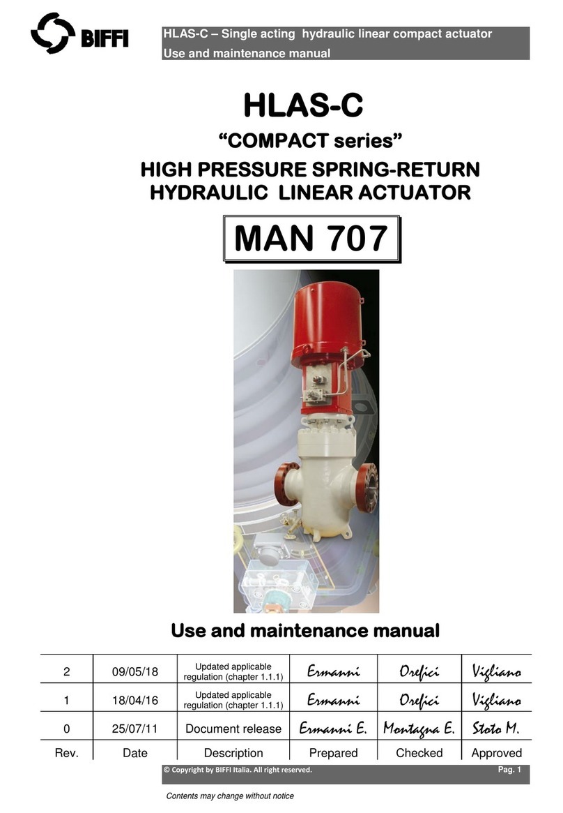
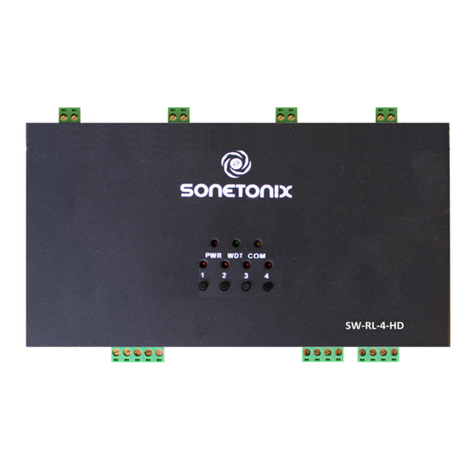
Tracer Profiler T229-2 User manual

OPERATION & MAINTENANCE MANUAL FOR TRACERCO
TM
T229 PROFILER Page 1 of 117
Tracerco Profiler
Tracerco Profiler Tracerco Profiler
Tracerco Profiler
Operation an
Operation an Operation an
Operation an
Maintenance Manual for
Maintenance Manual for Maintenance Manual for
Maintenance Manual for
T229
T229T229
T229-
--
-2
22
2
Controller
ControllerController
Controller
Document Number:
MI0027
Revision:
B
Date:
30th January 2017
REVISION STATUS
REVISION STATUSREVISION STATUS
REVISION STATUS
SIGNED / DATED
SIGNED / DATEDSIGNED / DATED
SIGNED / DATED
B
Up ate for T229-2 P.Chow
30/01/2017
S.Rowe
07/03/2017
C.Hart
07/03/2017
A
Original Issue D.Swalwell
28/06/2016
P.Chow
28/06/2016
S.Rowe
31/08/2016
REV
REVREV
REV
REVISION DESCRIPTION
REVISION DESCRIPTIONREVISION DESCRIPTION
REVISION DESCRIPTION
AUTHOR
AUTHORAUTHOR
AUTHOR
CHECKED
CHECKEDCHECKED
CHECKED
APPROVED
APPROVEDAPPROVED
APPROVED
Measurement Technology Centre,
The Moat,
Belasis Hall Technology Park,
Billingham,
Clevelan .
TS23 4ED
Tel: +44 (0) 1642 375500
Fax: +44 (0) 1642 370704
URL: www.tracerco.com
Functional Safety Relate
Functional Safety RelateFunctional Safety Relate
Functional Safety Relate
Pro uct
Pro uctPro uct
Pro uct
No mo ifications permitte without the
approval of an authorise person

OPERATION & MAINTENANCE MANUAL FOR TRACERCO
TM
T229 PROFILER Page 2 of 117
TABLE OF CONTENTS
1.
1.1.
1.
DOCUMENT CONTROL
DOCUMENT CONTROLDOCUMENT CONTROL
DOCUMENT CONTROL
................................
................................................................
................................................................
................................................................
..................................................
....................................
..................
7
77
7
1.1.
Notification List ............................................................................................................................................................... 7
1.2.
Contact Information ........................................................................................................................................................ 7
1.3.
24 Hours Emergency Callout Numbers ......................................................................................................................... 7
2.
2.2.
2.
INTRODUCTION
INTRODUCTIONINTRODUCTION
INTRODUCTION
................................
................................................................
................................................................
................................................................
.............................................................
..........................................................
.............................
8
88
8
2.1.
Principle of Operation for a T240 Profiler ...................................................................................................................... 8
2.2.
A Typical Instrument General Arrangement ................................................................................................................ 10
2.3.
Detector Configuration ................................................................................................................................................. 10
3.
3.3.
3.
INSTALLATION
INSTALLATIONINSTALLATION
INSTALLATION
................................
................................................................
................................................................
................................................................
.............................................................
..........................................................
.............................
11
1111
11
3.1.
Installation of Support Bracket (Optional) ................................................................................................................... 11
3.2.
Mechanical Installation (By Site) .................................................................................................................................. 11
3.3.
Bolt Torqueing Proce ure: ........................................................................................................................................... 11
4.
4.4.
4.
RADIOLOGICAL SAFETY
RADIOLOGICAL SAFETYRADIOLOGICAL SAFETY
RADIOLOGICAL SAFETY
................................
................................................................
................................................................
................................................................
..............................................
............................
..............
12
1212
12
4.1.
Source Isolation, Vessel Entry an Controlle Areas ................................................................................................. 12
4.2.
Cesium Profiler Variant ................................................................................................................................................. 12
5.
5.5.
5.
T229 HARDWARE
T229 HARDWARET229 HARDWARE
T229 HARDWARE
................................
................................................................
................................................................
................................................................
.........................................................
..................................................
.........................
13
1313
13
5.1.
Connection Details ........................................................................................................................................................ 13
5.1.1.
Connectors ............................................................................................................................................................ 13
5.1.2.
Terminal List .......................................................................................................................................................... 13
5.2.
Status In icators ........................................................................................................................................................... 14
6.
6.6.
6.
TRACERCO TOOLBOX SOF
TRACERCO TOOLBOX SOFTRACERCO TOOLBOX SOF
TRACERCO TOOLBOX SOFTWARE
TWARETWARE
TWARE
................................
................................................................
..............................................................
............................................................
..............................
15
1515
15
6.1.
Log in to Toolbox Software .......................................................................................................................................... 20
6.2.
Loa a Backup Configuration File ............................................................................................................................... 21
6.3.
The Calibrator Tool ....................................................................................................................................................... 22
6.3.1.
Instrument Configuration ..................................................................................................................................... 25
6.3.1.1.
TCP/IP Settings ............................................................................................................................................................26
6.3.1.2.
Engineering Units ........................................................................................................................................................26
6.3.1.3.
Set the Date and Time .................................................................................................................................................27
6.3.1.4.
Set the Instrument Tag ................................................................................................................................................28
6.3.1.5.
erify Modbus Master/Slave Settings .........................................................................................................................29
6.3.1.6.
Configure Source Type ................................................................................................................................................31
6.3.1.7.
Configure Measurement Range ..................................................................................................................................32
6.3.1.8.
Output Smoothing .......................................................................................................................................................33
6.3.1.9.
Pressure Correction .....................................................................................................................................................34
6.3.1.10.
Density Linearisation ..............................................................................................................................................35
6.3.1.11.
Phase Transition Densities ......................................................................................................................................36
6.3.1.12.
System Configuration ..............................................................................................................................................38
6.3.1.12.1.
Build Device List ..................................................................................................................................................39
6.3.1.12.2.
Fault Configuration .............................................................................................................................................40
6.3.1.12.3.
Temperature Limits ............................................................................................................................................42
6.3.1.13.
Device Configuration ..............................................................................................................................................43
6.3.1.13.1.
Sensor Arrangement ...........................................................................................................................................44
6.3.1.13.2.
Filtering Incoming Counts ...................................................................................................................................46
6.3.1.13.3.
Dead Time Settings .............................................................................................................................................47
6.3.1.14.
Stage Configuration ................................................................................................................................................48
6.3.1.14.1.
Stage Elevations..................................................................................................................................................49
6.3.1.15.
Save and Download Settings ...................................................................................................................................49

OPERATION & MAINTENANCE MANUAL FOR TRACERCO
TM
T229 PROFILER Page 3 of 117
6.3.2.
Calibration Proce ure .......................................................................................................................................... 49
6.3.2.1.
Define Reference Densities .........................................................................................................................................51
6.3.2.2.
Accumulating Counts ..................................................................................................................................................52
6.3.2.3.
Setting the Calibration Date ........................................................................................................................................55
6.3.2.4.
Save and Download Settings .......................................................................................................................................55
6.3.3.
Configuring Alarms an Fault Reporting ............................................................................................................. 56
6.3.3.1.
Defining Stage Criticality .............................................................................................................................................57
6.3.3.2.
Defining Alarm Criticality ............................................................................................................................................58
6.3.3.3.
Save and Download Settings .......................................................................................................................................58
6.3.4.
Defining I/O Parameters ....................................................................................................................................... 59
6.3.4.1.
Analogue Input Configuration .....................................................................................................................................59
6.3.4.1.1.
Time Constant (Seconds) ......................................................................................................................................59
6.3.4.1.2.
ADC Settings .........................................................................................................................................................59
6.3.4.1.3.
Scaled Engineering Units ......................................................................................................................................59
6.3.4.1.4.
Status Word ..........................................................................................................................................................60
6.3.4.2.
Analogue Output Configuration ..................................................................................................................................61
6.3.4.2.1.
Selecting Active / Passive Outputs ........................................................................................................................62
6.3.4.2.2.
Configuring the Source Register ...........................................................................................................................62
6.3.4.2.3.
Configuring Settings for 4mA and 20mA ..............................................................................................................62
6.3.4.2.4.
Control Mode 0: Source Data is Floating Point .....................................................................................................63
6.3.4.2.5.
Control Mode 1: Source Data is Unsigned 16-bit Integer .....................................................................................64
6.3.4.2.6.
Control Mode 2: Two State Output, Source Data is a Bit .....................................................................................65
6.3.4.2.7.
Control Mode 3: Two State Output, Float Comparison ........................................................................................66
6.3.4.2.8.
Control Mode 4: Two State Output, U16 Comparison..........................................................................................67
6.3.4.2.9.
Primary Fault Indication Bit Mask .........................................................................................................................68
6.3.4.2.10.
Secondary Fault Indication Bit Mask ..................................................................................................................69
6.3.4.2.11.
Range Clipping ....................................................................................................................................................70
6.3.4.2.12.
Slew Rate Limiting ..............................................................................................................................................70
6.3.4.2.13.
Status Word ........................................................................................................................................................70
6.3.4.3.
Digital Output Configuration .......................................................................................................................................71
6.3.4.3.1.
Control Mode 2: Two State Output with Bit Mask ...............................................................................................71
6.3.4.3.2.
Control Mode 3: Two State Output, Float Comparison ........................................................................................72
6.3.4.3.3.
Control Mode 4: Two State Output, U16 Comparison..........................................................................................73
6.3.4.3.4.
Common Fault Indication .....................................................................................................................................74
6.3.4.3.5.
Status Word ..........................................................................................................................................................74
6.3.4.3.6.
Output State .........................................................................................................................................................74
6.3.5.
Defining Mo bus Output Mapping ...................................................................................................................... 75
6.3.6.
Overview of the Comman Tool .......................................................................................................................... 76
6.3.6.1.
Reset to Factory Settings .............................................................................................................................................76
6.3.6.2.
Compatibility Mode.....................................................................................................................................................76
6.3.7.
Dynamic Density Ban Correction ...................................................................................................................... 77
6.3.7.1.
Choosing a Density Band to Correct ............................................................................................................................78
6.3.7.2.
Calculating an Average Reference Density ..................................................................................................................78
6.3.7.3.
Setpoint Offset ............................................................................................................................................................78
6.3.7.4.
Calculated Average Reference Density .......................................................................................................................79
6.3.7.5.
Calculated Setting for Phase Transition Density ..........................................................................................................79
6.3.7.6.
Density Band Correction Status Word .........................................................................................................................79
7.
7.7.
7.
SYSTEM START
SYSTEM STARTSYSTEM START
SYSTEM START-
--
-UP
UPUP
UP
................................
................................................................
................................................................
................................................................
.....................................................
..........................................
.....................
80
8080
80
8.
8.8.
8.
MAINTENANCE
MAINTENANCEMAINTENANCE
MAINTENANCE
................................
................................................................
................................................................
................................................................
............................................................
........................................................
............................
81
8181
81
8.1.
Wiring Connections ....................................................................................................................................................... 81
8.1.1.
Connection in the Safe Area ................................................................................................................................ 81
8.2.
Intrinsic Safety Consi erations .................................................................................................................................... 81
8.2.1.
Safety/Han ling Precautions ............................................................................................................................... 81
8.3.
Replacing a T240 Processor Boar ............................................................................................................................. 82

OPERATION & MAINTENANCE MANUAL FOR TRACERCO
TM
T229 PROFILER Page 4 of 117
8.4.
Routine Maintenance/Inspection ................................................................................................................................. 82
9.
9.9.
9.
TROUBLESHOOTING
TROUBLESHOOTINGTROUBLESHOOTING
TROUBLESHOOTING
................................
................................................................
................................................................
................................................................
...................................................
......................................
...................
83
8383
83
10.
10.10.
10.
APPENDIX A: T240 PRO
APPENDIX A: T240 PROAPPENDIX A: T240 PRO
APPENDIX A: T240 PROFILER VARIANT
FILER VARIANTFILER VARIANT
FILER VARIANT
................................
................................................................
.......................................................
..............................................
.......................
85
8585
85
10.1.
Installation ................................................................................................................................................................. 85
10.1.1.
Electrical Supply ................................................................................................................................................... 85
10.1.2.
Communications Fibre ......................................................................................................................................... 85
10.2.
Component Specifications ....................................................................................................................................... 86
10.2.1.
Performance Specifications ................................................................................................................................. 86
10.2.2.
Dip Pipes ............................................................................................................................................................... 86
10.2.3.
Ra ioactive Sources ............................................................................................................................................ 87
10.2.4.
Detector Assembly ............................................................................................................................................... 87
10.2.5.
Maximum an Minimum Operating Temperatures ............................................................................................. 87
10.2.6.
Storage Temperature ........................................................................................................................................... 87
10.2.7.
IP Rating ................................................................................................................................................................ 87
10.2.8.
Mechanical Dimensions ....................................................................................................................................... 88
10.2.9.
Power Cable an Glan s Specification............................................................................................................... 88
10.2.10.
Fibre Optic Cable Specification ........................................................................................................................... 88
10.2.11.
Electrical Specifications - Supply Details............................................................................................................ 88
10.2.12.
Stan ar s an Accre itation (Approval Certificates) ......................................................................................... 89
11.
11.11.
11.
APPENDIX B: REGISTER
APPENDIX B: REGISTERAPPENDIX B: REGISTER
APPENDIX B: REGISTER
MAP
MAPMAP
MAP
................................
................................................................
................................................................
................................................................
......................................
............
......
90
9090
90
11.1.
T229 Specific Details an settings .......................................................................................................................... 90
11.2.
Register escription ............................................................................................................................................... 100

OPERATION & MAINTENANCE MANUAL FOR TRACERCO
TM
T229 PROFILER Page 5 of 117
TABLE OF FIGURES
Figure 1 – Typical Separation Vessel ......................................................................................................................................... 8
Figure 2 – Typical Mo bus System Representation ................................................................................................................. 9
Figure 3 – Typical Representation ............................................................................................................................................ 10
Figure 4 - T240 Detector Cutaway ........................................................................................................................................... 10
Figure 5 - Opening & isolation of Sources ............................................................................................................................... 12
Figure 6 - Si e Nearest Ethernet Connector ........................................................................................................................... 13
Figure 7 - Si e Furthest from Ethernet Connector .................................................................................................................. 13
Figure 8 – PC to T229 Connection Diagram via Mo bus Slave ............................................................................................. 15
Figure 9 – Toolbox Start-up Screen ......................................................................................................................................... 15
Figure 10 – Toolbox Connection Wizar .................................................................................................................................. 16
Figure 11 – Toolbox Connection Protocol ............................................................................................................................... 16
Figure 12 – Toolbox Mo bus RTU Settings............................................................................................................................. 17
Figure 13 – Toolbox Connection Successful ........................................................................................................................... 18
Figure 14 – Toolbox Connection Wizar Error ........................................................................................................................ 18
Figure 15 – Toolbox Application ............................................................................................................................................... 19
Figure 16 – Toolbox Available Tools ........................................................................................................................................ 20
Figure 17 – Calibrator ................................................................................................................................................................ 21
Figure 18 - Calibrator Icons ...................................................................................................................................................... 21
Figure 19 – Toolbox Calibrator Rea ing Data from T229 ....................................................................................................... 23
Figure 20 – Toolbox Calibrator Writing Data to T229 .............................................................................................................. 24
Figure 21 – FLOWCHART FOR INSTRUMENT CONFIGURATION ........................................................................................ 25
Figure 22 – Mo bus TCP/IP Settings ....................................................................................................................................... 26
Figure 23 – Engineering Units ................................................................................................................................................... 26
Figure 24 – Calibrator: Setting Real-time Clock ...................................................................................................................... 27
Figure 25 – Calibrator: Setting the Instrument Tag ................................................................................................................. 28
Figure 26 – Calibrator: Mo bus Slave Settings ....................................................................................................................... 29
Figure 27 – Calibrator: Source Settings ................................................................................................................................... 31
Figure 28 – Calibrator: Measurement Range ........................................................................................................................... 32
Figure 29 – Calibrator: Output Smoothing ............................................................................................................................... 33
Figure 30 – Calibrator: Pressure Correction ............................................................................................................................ 34
Figure 31 – Calibrator: Density Linearisation ........................................................................................................................... 35
Figure 32 – Calibrator: Phase Densities ................................................................................................................................... 36
Figure 33 – Calibrator: Phase Density Application .................................................................................................................. 37
Figure 34 – FLOWCHART FOR SYSTEM CONFIGURATION ................................................................................................. 38
Figure 35 – Calibrator: Buil ing a Device List .......................................................................................................................... 39
Figure 36 – Calibrator: Mo bus Slave Settings ....................................................................................................................... 40
Figure 37 – Calibrator: Setting Temperature Limits ................................................................................................................ 42
Figure 38 – FLOWCHART FOR DEVICE CONFIGURATION ................................................................................................... 43
Figure 39 – Calibrator: Sensor Arrangement Example Detector A ......................................................................................... 44
Figure 40 – Calibrator: Sensor Arrangement Example Detector B ......................................................................................... 45
Figure 41 – Calibrator: Filtering ................................................................................................................................................ 46
Figure 42 – Calibrator: Dea Time Settings ............................................................................................................................. 47
Figure 43 – FLOWCHART FOR STAGE CONFIGURATION .................................................................................................... 48
Figure 44 – Calibrator: Defining Stage Elevation ..................................................................................................................... 49
Figure 45 – FLOWCHART FOR CALIBRATION PROCESS .................................................................................................... 50
Figure 46 – Calibrator: Defining Reference Densities ............................................................................................................. 51

OPERATION & MAINTENANCE MANUAL FOR TRACERCO
TM
T229 PROFILER Page 6 of 117
Figure 47 – Calibrator: Count Rate Gathering Tool ................................................................................................................. 52
Figure 48 – Calibrator: Count Rates (sample calibration ata) ............................................................................................... 54
Figure 49 – Calibrator: Setting the Calibration Date ............................................................................................................... 55
Figure 50 – FLOWCHART FOR DEFINING ALARM HANDLING ............................................................................................ 56
Figure 51 – Calibrator: Stage Criticality ................................................................................................................................... 57
Figure 52 – Calibrator: Alarm Criticality ................................................................................................................................... 58
Figure 53 – Calibrator: Analogue Input Dialog ......................................................................................................................... 59
Figure 54 – Calibrator: Example Analogue Output Configuration .......................................................................................... 61
Figure 55 – Active T229-2 Analogue Output ........................................................................................................................... 62
Figure 56 – Passive T229-2 Analogue Output ......................................................................................................................... 62
Figure 57 – Calibrator: Analogue Output Control Mo e 0 Dialogue ...................................................................................... 63
Figure 58 – Calibrator: Analogue Output Control Mo e 1 Dialogue ...................................................................................... 64
Figure 59 – Calibrator: Analogue Output Control Mo e 2 Dialogue ...................................................................................... 65
Figure 60 – Calibrator: Analogue Output Control Mo e 3 Dialogue ...................................................................................... 66
Figure 61 – Calibrator: Analogue Output Control Mo e 4 Dialogue ...................................................................................... 67
Figure 62 – Calibrator: Analogue Output Primary Fault In ication Mask............................................................................... 68
Figure 63 – Calibrator: Analogue Output Secon ary Fault In ication Mask ......................................................................... 69
Figure 64 – Calibrator: Digital Output Configuration for Control Mo e 2 .............................................................................. 71
Figure 65 – Calibrator: Digital Output Configuration for Control Mo e 3 .............................................................................. 72
Figure 66 – Calibrator: Digital Output Configuration for Control Mo e 4 .............................................................................. 73
Figure 67 – Calibrator: Output Mapping .................................................................................................................................. 75
Figure 68 – Toolbox: Comman Tool ....................................................................................................................................... 76
Figure 69 – Dynamic Density Ban Correction ....................................................................................................................... 77
Figure 70 - Diagram Showing Profiler Dome an Arming Ro ............................................................................................... 80

OPERATION & MAINTENANCE MANUAL FOR TRACERCO
TM
T229 PROFILER Page 7 of 117
1.
1.1.
1. Document Control
Document ControlDocument Control
Document Control
1.1. Notification List
This section gives etails of those parties who shoul be notifie upon release of each new revision:
Name Organisation Contact Details
Simon Lambert Tracerco (UK) 01642 375500
simon.lambert@tracerco.com
Steve Roe Tracerco (UK) 01642 375500
Paul Chow Tracerco (UK) 01642 375567
1.2. Contact Information
In the event of any safety or operational queries please contact Tracerco services for information.
Tracerco
TracercoTracerco
Tracerco
Measurement Technology Centre
The Moat
Belasis Hall Business Park
Billingham
Clevelan , UK
TS23 4ED
Tel: +44 (0)1642 375500
Fax: +44 (0)1642 370704
Email:
URL: www.tracerco.com
1.3. 24 Hours Emergency Callout Numbers
Instrument relate problem: Tel: +44 (0) 7885 667494
Ra iological Protection A visor: Fax: +44 (0) 7889 828968
This ocument is a private an confi ential communication an the property of Tracerco Lt , it must not be loane or
copie without the prior consent of Tracerco Lt an must be returne .

OPERATION & MAINTENANCE MANUAL FOR TRACERCO
TM
T229 PROFILER Page 8 of 117
2.
2.2.
2. Intro uction
Intro uctionIntro uction
Intro uction
Separation vessels contain pro ucts such as Gas, Foam, Oil, Emulsion, Water, an San which naturally gravitate into
ifferent phases as shown in Figure 1. Each phase has a ifferent ensity.
The Tracerco Profiler
TM
is an a vance Specialist Measurement instrument use to i entify ifferent phases within
multiphase systems. Employing awar winning an patente techniques it measures the gamma absorption of the
process material. This enables a meaningful an accurate measurement of the vertical ensity istribution within vessels
to be ma e.
The instrument uses a vertical array of sources an
etectors (Geiger Müller Tubes), to measure an map the
ifferent process phases with respect to vessel height.
Reliable assessment of both the interface quality an the
level of the interfaces present within the vessel are
achievable.
Measurements can be separate into a maximum of up
to ten ifferent ensity ban s or phases. The elevation of
the various phases can be calculate an outputs given
with respect to the instrument height.
The information provi e can then be use to give
outputs to control oil an water interface levels, control
an monitor the effects of chemical a itives or establish
effective san washing regimes.
Figure
Figure Figure
Figure 1
11
1
–
––
–
Typical Separation Vessel
Typical Separation VesselTypical Separation Vessel
Typical Separation Vessel
2.1. Principle of Operation for a T240 Profiler
The T240 Profiler can support either 1 or 2 separate etector arrays epen ing upon the application. On occasion 2
etectors are require so that the power level in each is low enough to meet the requirements of intrinsic safety over
longer measurement ranges.
Each etector may contain up to 75 Geiger Müller tubes giving a maximum of 150 for this instrument although again, the
number of actual tubes specifie an their configuration epen s upon the application.
With sources loa e an the arming ro in the open position the process material present between the source an
etector will attenuate the ra iation. The amount of attenuation measure by the Geiger Muller is then use to calculate
the ensity of the intervening material.
The T229 controller collects information from each in ivi ual GM tube, an through a series of calculations etermines
the ensity of the material. This enables a ensity or interface profile of the vessel to be constructe . Density ban s are
allocate for each of the phases (typically Gas, Foam, Oil, Emulsion, Water an San ). Up to 6 interfaces may be
configure . The top level of these phases can then be calculate with respect to instrument height.
.

OPERATION & MAINTENANCE MANUAL FOR TRACERCO
TM
T229 PROFILER Page 9 of 117
Figure
Figure Figure
Figure 2
22
2
–
––
–
Typical Mo bus System Representation
Typical Mo bus System RepresentationTypical Mo bus System Representation
Typical Mo bus System Representation

OPERATION & MAINTENANCE MANUAL FOR TRACERCO
TM
T229 PROFILER Page 10 of 117
2.2. A Typical Instrument General Arrangement
A iagram of a single etector system is shown below. The Profiler is typically locate on a flange at the top of a vessel
an consists of 3 main components that make up the outer instrument housing. These are the ip-pipes, neck an ome.
Figure
Figure Figure
Figure 3
33
3
–
––
–
Typical Representation
Typical RepresentationTypical Representation
Typical Representation
The ip-pipes project into the separator through the vessel flange an consist of a source assembly an etector probe(s).
The source assembly hol s the source ro in the collimator. This source ro contains a series of sources istribute
along its length. The ro is attache to an arming mechanism allowing the user to isolate the sources within the evice.
The collimator has a series of small holes, which align with each source position when the ro is in the open position.
This allows narrow beams of ra iation to be irecte towar s the etectors in the a jacent etector tube(s). When the
arming mechanism is locke in the shut position the alignment of the sources an the collimator is such that the sources
are isolate an the ra iation from the gauge is at a safe level.
The ip-pipes are effectively a sleeve an atum for the instrument components an provi e the pressure seal with the
vessel flange.
2.3. Detector Configuration
Each etector probe is populate with Geiger Müller tubes positione along its length an encase within a protective
sleeve. Each probe assembly is house within the etector ip pipe(s).
A pulse-shaping amplifier, mounte on the etector probe circuit boar , is
use to pro uce a useable pulse signal for each Geiger tube output. The
output of these amplifiers is connecte to the signal processing boar via a
multi-way cable.
The number an spacing of sources an etectors is configurable an
governs the range an resolution of the instrument.
The tubes are istribute over the range of the instrument to provi e the
require range an resolution of the application. On multi- etector systems
the tubes may be offset such that a better resolution is achieve .
Figure
Figure Figure
Figure 4
44
4
-
--
-
T240 Detector Cutaway
T240 Detector CutawayT240 Detector Cutaway
T240 Detector Cutaway
DOME HEIGHT
DOME HEIGHTDOME HEIGHT
DOME HEIGHT
FLANGE
FLANGE FLANGE
FLANGE
DIP PIPE

OPERATION & MAINTENANCE MANUAL FOR TRACERCO
TM
T229 PROFILER Page 11 of 117
3.
3.3.
3. Installation
InstallationInstallation
Installation
There are two main aspects of the profiler installation:
1.
Mechanical
2.
Electrical an Communications
The mechanical components are generally shippe as the following components:
1.
Assemble Profiler unit consisting of probes, ip pipes, neck, ome, collimator
2.
Support bracket
3.
Communications breakout boxes.
4.
Source, in arming ro s an A type container
3.1. Installation of Support Bracket (Optional)
The support bracket is not use in all profiler applications. Where require the project will be issue with job specific
mechanical rawings that inclu e a general arrangement rawing an a lower support arrangement rawing (if require ).
Affix bottom support to suitable internal clips or local internal support at the height shown on general arrangement
rawing. Ensuring the arrows on the base are positione in the irection of liqui flow.
Insert the ip-pipe(s) in to the vessel following review of installation information below. Pass the ip-pipe(s) through the
annulus of the bottom support, tightening the bolts fix the ip pipe in place.
Torque the ip-pipe flange to correct settings. Please refer to project specific pressure vessel calculations for suggeste
gasket type an bolt torque settings.
3.2. Mechanical Installation (By Site)
All ip-pipe assemblies will be ispatche packe into a woo en crate(s). Each woo en crate containing a ip-pipe
assembly will be suitable for han ling by fork-lift truck an slings an can be store in a normal store. It is essential the
ip pipes are kept ry. If the crate is opene uring storage for inspection then Tracerco recommen the crate is re-
seale to prevent moisture ingress.
To install carefully remove the li of the crate, where lifting equipment is require an fix lifting shackles through the lifting
lugs fitte to the titanium flange. It is recommen e that the lifting shackle is a 2te rate large 'D' shackle (BS 3032 1958).
For internally mounte ip-pipes, ensure that the flange face of vessel nozzle is clean an place the joint gasket on the
nozzle flange. Using a suitable hoist lift the ip-pipe assembly out of its crate an into position above the vessel nozzle.
Carefully lower the ip-pipe assembly through the nozzle an into the vessel. When the ip-pipe is approximately 200mm
from the vessel nozzle carefully remove the fixing bolts that hol the profiler neck an ome to the titanium flange. With
the neck an ome supporte continue to lower the ip-pipe assembly until it mates with the vessel nozzle, ensuring that
the ip-pipe passes through the bottom support bracket as above, if fitte .
The integrity of the titanium ip-pipe assembly must be protecte by a suitable size relief valve fitte to the vessel.
3.3. Bolt Torqueing Proce ure:
Please refer to project specific pressure vessel calculations for suggeste gasket type an bolt torque settings.
1.
All nuts to be capable of being run own their respective bolts by han .
2.
Ensure threa s are suitably lubricate .
3.
Assemble the joint an secure all nuts by han .

OPERATION & MAINTENANCE MANUAL FOR TRACERCO
TM
T229 PROFILER Page 12 of 117
4.
4.4.
4. Ra iological Safety
Ra iological SafetyRa iological Safety
Ra iological Safety
It is our normal practice to supply all equipment as specifie except the ra ioactive sources. These will normally be
shippe to site prior to commissioning by Tracerco Services engineers. The sources will be shippe in a suitable type
“A” container. This ensures that the sources are safely packe an shiel e for transport. When shippe to site, the
sources shoul be kept in a safe area (e.g. Ra iographer’s store) until the arrival of Tracerco Services commissioning
engineers, who will install the source array into its ip-pipe. Prior to arrival of the sources, the site registration shoul be
amen e to inclu e the a itional sources. Tracerco’s Ra iation Protection A visor (RPA) may be contacte for a vice
with regar to licenses, registration, etc.
4.1. Source Isolation, Vessel Entry an Controlle Areas
The sources are containe within a single arming ro which can be locke with the sources in place. The lock must not
be remove by unauthorise persons.
For vessel entry uring shut own the arming ro must be locke shut to isolate the sources. This is achieve by pushing
own on the lever at the neck of the profiler (as shown in Figure 5) an inserting a pa lock into the hole provi e .
For UK applications a controlle area is man atory aroun the Profiler, vessel or any area where a ose of ose > 7.5
micro-Sieverts/hr is measure . For non UK applications limits may iffer epen ing on local regulations.
4.2. Cesium Profiler Variant
These sources emit a high energy (662keV) gamma ray. When entering the vessel a controlle area is require even when
isolate . The application specific ra iological operating proce ures must be use when ealing with this type of profiler.
Figure
Figure Figure
Figure 5
55
5
-
--
-
Opening & isolation of Sources
Opening & isolation of SourcesOpening & isolation of Sources
Opening & isolation of Sources
OPEN
OPENOPEN
OPEN
SHUT
SHUTSHUT
SHUT

OPERATION & MAINTENANCE MANUAL FOR TRACERCO
TM
T229 PROFILER Page 13 of 117
5.
5.5.
5. T229
T229 T229
T229 Har ware
Har wareHar ware
Har ware
The information containe within this section etails how to configure an maintain the functionality of the Tracerco
Profiler
TM
through the Tracerco Toolbox software.
5.1. Connection Details
The T229 mo ule is house in a polyami e DIN rail mounting enclosure, 22.5 mm x 99 mmm x 114.5 mm. Connections
are ma e using 4 way 5mm pitch plug in terminals. The terminals will accommo ate wires up to 2.5 mm².
5.1.1. Connectors
1 2 3 4
5 6 7 8
9 10 11 12
13
14 15 16
17
18 19 20
21
22 23 24
Figure
Figure Figure
Figure 6
66
6
-
--
-
Si e Nearest Ethernet Connector
Si e Nearest Ethernet ConnectorSi e Nearest Ethernet Connector
Si e Nearest Ethernet Connector
Figure
Figure Figure
Figure 7
77
7
-
--
-
Si e Furthest from Ethernet Connector
Si e Furthest from Ethernet ConnectorSi e Furthest from Ethernet Connector
Si e Furthest from Ethernet Connector
5.1.2. Terminal List
Terminal
TerminalTerminal
Terminal
Function
FunctionFunction
Function
1
11
1
Analogue Output Channel 1
(active+ or passive
-
)
2
22
2
Analogue Output Channel 1 (active- or passive+)
3
33
3
Analogue Output Channel 2 (active+ or passive-)
4
44
4
Analogue Output Channel 2 (active- or passive+)
5
55
5
Analogue Output Channel 3 (active+ or passive-)
6
66
6
Analogue Output Channel 3
(active
-
or passive+)
7
77
7
Analogue Output Channel 4 (active+ or passive-)
8
88
8
Analogue Output Channel 4 (active- or passive+)
9
99
9
Analogue Output Channel 5 (active+ or passive-)
10
1010
10
Analogue Output Channel 5 (active
-
or passive+)
11
1111
11
DC Power input 24 Volts ±10%
12
1212
12
DC Power input 0 Volts
13
1313
13
4-20mA Analogue Input +
14
1414
14
Mo bus RTU Slave (RS485) - B
15
1515
15
Mo bus RTU Slave (RS485)
–
A
16
1616
16
Mo bus RTU Slave (RS485) - GND
17
1717
17
4-20mA Analogue Input – OR Volt Free Contact A
18
1818
18
Mo bus RTU Master 1 (RS485) – B
19
1919
19
Mo bus RTU Master
1
(RS485)
–
A
20
2020
20
Mo bus RTU Master 1 (RS485) – GND
21
2121
21
Volt Free Contact B
22
2222
22
Mo bus RTU Master 2 (RS485) – B
23
2323
23
Mo bus RTU Master
2
(RS485)
–
A
24
2424
24
Mo bus RTU Master 2 (RS485) – GND

OPERATION & MAINTENANCE MANUAL FOR TRACERCO
TM
T229 PROFILER Page 14 of 117
5.2. Status In icators
Four LEDs are provi e to in icate the instrument status, an are visible on the front panel of the mo ule. The functions
of the LEDs are as follows:
Label
LabelLabel
Label
State
StateState
State
Meaning
MeaningMeaning
Meaning
M1
Green / black flash
Green / re flash
Stea y re
Off
Vali message exchange
Invali message / message exchange
Communications error, port not operating
Port not enable
M2
Green / black flash
Green / re flash
Stea y re
Off
Vali message exchange
Invali message / message exchange
Communications error, port not operating
Port not enable
Host
Green flash
Blue flash
Re flash
Off
Vali message receive (Mo bus RS485)
Vali message receive (Mo bus over TCP/IP)
Invali message receive
Port not being polle
Status
Green
Yellow
Re
All evices communicating, instrument OK
Instrument running but a warning reporte
Instrument not running, error reporte

OPERATION & MAINTENANCE MANUAL FOR TRACERCO
TM
T229 PROFILER Page 15 of 117
6.
6.6.
6. Tracerco Toolbox Software
Tracerco Toolbox SoftwareTracerco Toolbox Software
Tracerco Toolbox Software
Tracerco provi e the ToolBox Software application for the setup, configuration an monitoring of their instrumentation.
Connection to the T229 Controller is achieve using either the Mo Bus slave port or via one of the two Ethernet TCP/IP
ports on the front of the unit. The Mo Bus slave port communicates using RS485 so a convertor is require between the
PC an the T229.
USB to RS485
Convertor
Laptop
15(B)
14(A)
16(G) T229 Controller
Modbus Slave 1
(B)
(A)
(G)
Figure
Figure Figure
Figure 8
88
8
–
––
–
PC to T229 Connection Diagram
PC to T229 Connection DiagramPC to T229 Connection Diagram
PC to T229 Connection Diagram
via Mo bus Slave
via Mo bus Slavevia Mo bus Slave
via Mo bus Slave
NOTE
NOTENOTE
NOTE
THE PC/LAPTOP MUST USE WINDOWS 7 OR HIGHER FOR COMPATIBILITY PURPOSES.
THE PC/LAPTOP MUST USE WINDOWS 7 OR HIGHER FOR COMPATIBILITY PURPOSES. THE PC/LAPTOP MUST USE WINDOWS 7 OR HIGHER FOR COMPATIBILITY PURPOSES.
THE PC/LAPTOP MUST USE WINDOWS 7 OR HIGHER FOR COMPATIBILITY PURPOSES.
TO CONNECT VIA
TO CONNECT VIA TO CONNECT VIA
TO CONNECT VIA MODBUS TCP/IP
MODBUS TCP/IP MODBUS TCP/IP
MODBUS TCP/IP USE
USE USE
USE THE RJ45 CONNECTIONS ON THE FRONT OF THE UNIT
THE RJ45 CONNECTIONS ON THE FRONT OF THE UNITTHE RJ45 CONNECTIONS ON THE FRONT OF THE UNIT
THE RJ45 CONNECTIONS ON THE FRONT OF THE UNIT
Run the Tracerco Toolbox 2 application from your Win ows start menu. The start-up screen below will be shown for a
short time while initialisation takes place:
Figure
Figure Figure
Figure 9
99
9
–
––
–
Toolbox Start
Toolbox StartToolbox Start
Toolbox Start-
--
-up Screen
up Screenup Screen
up Screen
Once initialisation is complete the following ialogue is isplaye , click Next >
Next >Next >
Next > to continue.

OPERATION & MAINTENANCE MANUAL FOR TRACERCO
TM
T229 PROFILER Page 16 of 117
Figure
Figure Figure
Figure 10
1010
10
–
––
–
Toolbox Connection Wizar
Toolbox Connection WizarToolbox Connection Wizar
Toolbox Connection Wizar
Figure
Figure Figure
Figure 11
1111
11
–
––
–
Toolbox Connection Protocol
Toolbox Connection ProtocolToolbox Connection Protocol
Toolbox Connection Protocol
Click on the Mo bus
Mo busMo bus
Mo bus or Mo bu
Mo buMo bu
Mo bus TCP/IP
s TCP/IPs TCP/IP
s TCP/IP button to continue epen ing on your connection to the T229 unit.

OPERATION & MAINTENANCE MANUAL FOR TRACERCO
TM
T229 PROFILER Page 17 of 117
Figure
Figure Figure
Figure 12
1212
12
–
––
–
Toolbox
Toolbox Toolbox
Toolbox Mo bus
Mo bus Mo bus
Mo bus RTU
RTU RTU
RTU Settings
SettingsSettings
Settings
Using the rop own list provi e select the Serial Port
Serial PortSerial Port
Serial Port which is going to be use to make the connection to the T229.
The Mo e
Mo eMo e
Mo e, Bau Rate
Bau RateBau Rate
Bau Rate, Parity
ParityParity
Parity, Stop Bits
, Stop Bits, Stop Bits
, Stop Bits an Slave A ress
Slave A ressSlave A ress
Slave A ress shoul be set as shown for a mo ule with efault settings.
OR…
Enter the IP A ress
IP A ressIP A ress
IP A ress of the T229 Unit. Note that the IP a ress of your PC must be on the same network. Leave the
P
PP
Port
ort ort
ort setting at 502
502502
502, this is the efault for a Mo Bus connection. Finally, select the correct Slave A ress
Slave A ressSlave A ress
Slave A ress, you can
etermine this by examining the T229 configuration file while offline.
When your selections are complete click Next >
Next >Next >
Next >

OPERATION & MAINTENANCE MANUAL FOR TRACERCO
TM
T229 PROFILER Page 18 of 117
Figure
Figure Figure
Figure 13
1313
13
–
––
–
Toolbox Connection Successful
Toolbox Connection SuccessfulToolbox Connection Successful
Toolbox Connection Successful
If the connection is successful then the serial number is reporte as 229YYNNNN (where YY is the year of manufacture
an NNNN is a unique T229 Serial Number). At this point select Finish
FinishFinish
Finish to continue.
If the serial number is reporte as zero, then the mo ule has lost its factory settings. Contact Tracerco for a vice if this
is the case, contact etails are provi e in section 1.2. Alternatively, if connection to the T229 is not successful then the
following ialogue box will be isplaye .
Figure
Figure Figure
Figure 14
1414
14
–
––
–
Toolbox
ToolboxToolbox
Toolbox
Connection Wizar Error
Connection Wizar ErrorConnection Wizar Error
Connection Wizar Error

OPERATION & MAINTENANCE MANUAL FOR TRACERCO
TM
T229 PROFILER Page 19 of 117
At this point verify:
•
Wiring etails
•
Serial settings
•
Power is applie to the instrument
•
Check the status in icators escribe in section 5.2
The next screen is the main toolbox screen, showing the connection ma e, an the tools available. The range of available
tools shown epen s on the level of access applie to the user logge in to Toolbox.
Figure
Figure Figure
Figure 15
1515
15
–
––
–
Toolbox Application
Toolbox ApplicationToolbox Application
Toolbox Application

OPERATION & MAINTENANCE MANUAL FOR TRACERCO
TM
T229 PROFILER Page 20 of 117
6.1. Log in to Toolbox Software
Click on the Log In
Log InLog In
Log In button locate at the top right han corner of the screen. When the ialogue box appears, click on
the User
UserUser
User rop own list an select the Supervisor
SupervisorSupervisor
Supervisor option (customer login), Passwor – Bar een
Bar eenBar een
Bar een.
When logge in successfully the toolbox software will refresh the overview screen an isplay the list of tools which are
available for selection.
Figure
Figure Figure
Figure 16
1616
16
–
––
–
Toolbox
Toolbox Toolbox
Toolbox Available Tools
Available ToolsAvailable Tools
Available Tools
The screen will show the tools available to the Supervisor for the connecte evice. To launch a tool, click on the
appropriate button in the available tools section. To return to the Toolbox screen from any tool, click on Devices
DevicesDevices
Devices.
