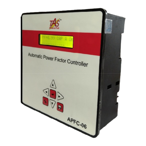
TAS POWERTEK APFC-05 User manual

Automatic Power Factor Controller
APFC-05
User Manual
Version 1.0
TAS POWERTEK PVT.LTD.VERSION 1.0 Updated on: FEB. 18, 2015

NOTE
These instructions do not purport to cover all details or
variations in equipment, nor to provide for every possible
contingency to be met in connection with installation,
operation or maintenance.
Should further information be desired or should particular
problems arise which are not covered sufficiently for the
purchasers purposes, the matter should be referred to our
office.
The contents of this instruction Manual shall not become
part of or modify any prior or existing agreement or
relationship. Any statements contained herein do not create
new warranties or modify the existing warranty.
The reproduction, transmission or use of this document or its contents is not
permitted without express written authority. Offenders will be liable for damages. All
rights are reserved.
Because of continuous improvements efforts by TAS PowerTek in their Product’s Features and
Specifications, the Product as well as the content of the User Manual is likely to get updated.
Therefore, please always refer to the User Manual supplied to the customer along with the
Product, at the time of product dispatch.
CAUTIONS:
High voltage!
APFC may only be used indoor!
Make sure that the discharge time set in the controller matches the capacitor discharge time!
This User Manual for TAS APFC-05/xx Controller refers to the Firmware Version 1.0.0
Dated: 9th Jan. 2015.
Power Factor Controller APFC-05
TAS POWERTEK PVT.LTD. VERSION 1.0 Updated on: FEB. 18, 2015

- 1 -
Index
Index page -- 1
Features -- 2
Specifications -- 3
Mechanical dimensions -- 3
Front fascia -- 4
Back Side Terminals - - 5
PF correction technique -- 6 & 7
Typical wiring scheme -- 8 & 9
Control wiring Scheme -- 10
Rear side terminals -- 11
Front Fascia LCD Screen Details -- 12 & 13
Keyboard details -- 14
Display of various parameters -- 15
Sub menu for display of parameters -- 16
Method of Keyboard / Display usage -- 17 to 19
Keyboard / Display operations -- 20 & 21
Edit Parameters
General & IO -- 22
System -- 22
Fault -- 23 to 25
Steps -- 26 & 27
Step utilization -- 28
Commissioning Instructions -- 29 & 30
Troubleshooting procedure -- 31 & 32
Manufacturer’s Contact Details -- 33
TAS POWERTEK PVT.LTD. VERSION 1.0 Updated on: FEB. 18, 2015

Features
•Totally Micro-processor controlled Digital Signal processing
logic for measurements and control.
•Load V, I, odd harmonic coefficients up to 15th harmonic.
•Various modes for switching, viz:
Binary
Un-equal (user defined)
C-Series (preset series)
E-Series (user defined)
•Output banks control for either 4 , 6 or 8 Capacitor Banks.
•Standard 96x96 mm Plastic Cabinet for panel door flush
mounting.
•Protections provided:
Over/Under Voltage
Over / Under load current
Over Temperature internal to APFC-05 Unit
All these are user settable
- 2 -
TAS POWERTEK PVT.LTD. VERSION 1.0 Updated on: FEB. 18, 2015

Specifications
•Feed-back Voltage: 1-Phase, 2-Wire, 230Volt Ac, (+/- 10%)
•AC Mains Supply Line Frequency: 50/60 Hz.
•Current input: Selectable 1A or 5A for load.
•Auxiliary Supply: 1-Phase, 230V (+/- 10%).
•Correction time:
Selectable in Seconds from 1 Sec. to 65530 Sec.
•Output Commands: 4 (APFC-05/4) or 6 (APFC-05/6)
or 8 (APFC-05/8).
(Isolated ‘NO’ contacts of rating Inductive Load 0.5A/250Vac).
•Operating Temperature: 0 to +55oC.
•Storage temperature: 0 to +70oC.
•Relative Humidity: 10% to 95% (Non Condensing).
•AC Mains Supply frequency: 47Hz to 53Hz,or 57Hz to 63Hz.
- 3 -
Mechanical
dimensions:
Recommended size for cut-out on panel door is 92 x 92 mm.
Max. weight: (with clamps and terminals) = Approx. 0.6 Kgs.
All Dimensions
given are in mm.
100
96
96
91
91
TAS POWERTEK PVT.LTD. VERSION 1.0 Updated on: FEB. 18, 2015

- 4 -
Front fascia
Keyboard, LCD display
LCD Display
Key pad
PF=0.98 IND A OK
LCD Display Contrast Adjustment
Slot for small Allen-Key, at the Top Surface
TAS POWERTEK PVT.LTD. VERSION 1.0 Updated on: FEB. 18, 2015

BACK SIDE TERMINALS
•Auxiliary &
Measurement Voltage Load Current CT
Output Terminals
5
TAS POWERTEK PVT.LTD. VERSION 1.0 Updated on: FEB. 18, 2015

PF correction technique
kW.
kVAr
(Ind)
kVAr
(Cap)
PFLOWER.
PFUPPER.
-kW.
PFLOWER.
PFUPPER.
Case-1: PF-UPPER & PF-LOWER both set as inductive:
smallest
Capacitor bank
kVAr x 2 width.
- 6-
kVAr
(Ind)
kVAr
(Cap)
PFLOWER.
PFUPPER.
-kW
PFLOWER.
PFUPPER.
smallest
Capacitor bank
kVAr x 2 width.
Case-2: PF-UPPER as Capacitive & PF-LOWER set as Inductive:
kW
No change band.
Capacitor addition band.
Capacitor removal band.
TAS POWERTEK PVT.LTD. VERSION 1.0 Updated on: FEB. 18, 2015

There are two PF set points to be set in APFC-05. The UPPER limit and
the LOWER limit. APFC-05 ensures that PF-UPPER is never exceeded.
Additionally, “No change band” to minimum kVAr band size equal to
smallest bank kVAr * 2 ensures no hunting during the low kW loading.
APFC-05 is normally set for PF settings as per first two diagrams shown
where PF LOWER is inductive. This philosophy helps to optimize the
system maximum kVAr to be used as well as reduces the number of
switching operations during higher loading conditions. This ensures better
life expectancies of the switched capacitors as well as the switching
devices.
This methodology of kVAr compensation reduces the complex settings
that are used by conventional PF relays. The settings like C/K ratio and
kVAr offsets/shifts are eliminated which makes APFC-05 user friendly and
thus easy to commission.
- 7 -
kVAr
(Ind)
kVAr
(Cap)
PFLOWER.
PFUPPER.
-kW
PFLOWER.
PFUPPER.
smallest
Capacitor bank
kVAr x 2 width.
kW.
Case-3: PF-UPPER & PF-LOWER both set as Capacitive:
No change band.
Capacitor addition band.
Capacitor removal band.
TAS POWERTEK PVT.LTD. VERSION 1.0 Updated on: FEB. 18, 2015

- 8-
Typical wiring diagram for PF correction
Conventional LT side PF
improvement system
schematic
As per this scheme, the load sensing CT is put between
the source and the PF correction capacitor banks. This is
as per diagram shown above. The voltage feedback is
taken from the LT bus system itself.
This type of scheme is used when user is interested in
maintaining the healthy Power factor on secondary side of
the transformer.
This scheme is preferred with LT consumers of electricity,
where the metering is carried out on LT side.
Scheme - 1
L
O
A
D
HT side LT side
Load CT
TAS POWERTEK PVT.LTD. VERSION 1.0 Updated on: FEB. 18, 2015

- 9 -
Typical wiring diagram for PF correction
LT Power Factor
compensation with HT
side feedback
Scheme - 2
L
O
A
D
HT side LT side
CT/PT on
HT side
As per this scheme, the load sensing CT is put at the input
of the transformer on HT side.
This scheme is preferred with LT consumers of electricity,
where the metering is carried out on HT side.
This scheme gives the compensation against magnetizing
current of the transformer. Thus, for HT metering able to
give more accurate results.
TAS POWERTEK PVT.LTD. VERSION 1.0 Updated on: FEB. 18, 2015

- 10 -
Control wiring diagram
Either of the above specified schemes can be selected by
the user based on the system requirement.
L
O
A
D
L3
N
S1 S2
Load
Current L1 N
APFC-05
P1 P2
L2
L1
TAS POWERTEK PVT.LTD. VERSION 1.0 Updated on: FEB. 18, 2015

Auxiliary & Measurement
voltage Connection
230 V, 1Phase, 2Wire
Load CT Connection
Selectable 1A or 5A
Example: Select either
S1 ( 1A) or S5 (5A)
along with S ( common)
Output commands to capacitor contactors.
APFC 05
COM = common,
C1…… C8 = potential free relays, maximum of up to 8 Stages,
0.5A, 230Vac, Inductive Load. F2 Fast-Blow Fuse Protected.
Rear side terminals –measurement
voltage, measurement current
- 11 -
N
L1
S1
S5
S
C8
C7
C6
C5
C4
C3
C2
C1
COM
TAS POWERTEK PVT.LTD. VERSION 1.0 Updated on: FEB. 18, 2015

Front fascia –
LCD screen, LED indications
- 12 -
First line of display indicates the PF value, inductive / capacitive
PF, mode of operation and fault / OK status:
“PF = 1.00” indicates the overall PF of the system.
“IND” or “CAP” indicates if this PF is inductive or capacitive respectively.
“A” or “M” indicates the Auto and Manual mode of operation respectively.
“OK” (blinking) indicates status of the system, healthy or faulty.
Last two characters represent one of the following status:
PF=1.00 IND A OK
bank is in ON state.
bank is in OFF state.
bank is declared as FIXED & is in ON state.
bank is declared FAULTY & not available for use
output stage is not used in the system.
bank is in DISCHARGE mode (blinking red LED)
Symbol Description
Over frequency
Outputs are disabled
Measurement voltage is absent
Controller status is okay
OF
OD
VA
OK
Second line indicates the status of each capacitor bank by
symbols. The status is also shown by LEDs provided on the front
fascia. Following table gives the description of symbols & LEDs.
Under frequency
Over internal temperature
Over voltage
UF
UT
UV
OV
Under voltage
TAS POWERTEK PVT.LTD. VERSION 1.0 Updated on: FEB. 18, 2015

Example of a typical LCD display screen is show below:
Meaning of this screen contents:
Total no. of banks connected is seven.
Power Factor at Load sensing CT is 0.98 ‘IND’ Inductive.
(‘CAP’ defines Capacitive).
Unit is operating in ‘A’ Auto mode. (‘M’ defines Manual mode)
Total number of banks that are operational are eight.
Bank no. 1 is declared as fixed and is in ON condition.
Bank nos. 2 and 3 are in ON condition.
Bank no. 4 is declared as faulty.
Bank no. 5 is in discharging state.
Bank nos.6 and 7 are in off state. Ready to be switched on.
Bank (output) no. 8 is not used / not connected.
PF=0.98 IND A OK
- 13 -
Front fascia –
LCD screen
TAS POWERTEK PVT.LTD. VERSION 1.0 Updated on: FEB. 18, 2015

Keyboard with soft touch keys are provided on the front facia
of the controller. The various keys are:
- 14 -
Front fascia –
Keyboard
UP key. Used to scroll up the menu screen;
increment values when entering numbers.
Also used for changing the status of banks.
DOWN key. Used to scroll down the menu
screen; decrement values when entering
numbers.Also use to change status of bank.
RIGHT key. Used to shift the cursor to right;
also used to increase the contrast of LCD in
default display screen mode.
LEFT key. Used to shift the cursor to left;
also used to decrease the contrast of LCD in
default display screen mode.
ENTER key. Used for entering a submenu
or for setting up values.
PROGRAM key. Used for selecting modes
of operation and editing of parameters
MEMORY key. Used to save all changes
made in Edit Parameters menu.
TAS POWERTEK PVT.LTD. VERSION 1.0 Updated on: FEB. 18, 2015

This is factory set default display
screen giving information on PF,
mode, bank & controller status.
Overall values gives the average
values of system parameters –V, I,
kW, kVAr, kVA. Load side PF, kVAr,
kVA & frequency.
Displays values of PF, kW, kVA,
kVAr.
Displays average values of THD for
V, I, harmonics up-to 15th.
Displays the measured kVAr value
of each connected output step.
Displays the internal (cabined)
temperature.
Displays the version of software.
- 15 -
Values of various parameters can be viewed by using UP / DN
keys & then pressing ENT key. To exit a sub-menu press MODE.
Display of various parameters
PF=0.98 IND A OK
Display
Overall Values
Display
Power
Display
Harmonics
Display
Step kVAr
Display
Aux-Function
TAS PowerTek India
APFC 05
TAS POWERTEK PVT.LTD. VERSION 1.0 Updated on: FEB. 18, 2015

- 16 -
continued..
Sub menu for display of parameters
TAS POWERTEK PVT.LTD. VERSION 1.0 Updated on: FEB. 18, 2015

Method for keyboard / display usage
Flowchart for entering into different modes:
Enter the 4 digit
Password by using
& keys.
PRESS
Enable If Password
Option is
Enable/Disable.
Disable
IF
PASSWORD
Correct?
NO YES
Continued on next page
*
PRESS
Enter Password:
****
Default
Display
mode
PRESS
-17 –
TAS POWERTEK PVT.LTD. VERSION 1.0 Updated on: FEB. 18, 2015

*
#
1 2 3 4 5 6 7 8 9 10 11 12 13 14 15 16
- 18 -
Continued on next page
Select
1. Edit Parameter
Select
2. Auto Operation
Select
3. Manual Operation
Default
Display
mode
TAS POWERTEK PVT.LTD. VERSION 1.0 Updated on: FEB. 18, 2015
Table of contents
Other TAS Controllers manuals
Popular Controllers manuals by other brands
Unitronics
Unitronics UniStream Built-in Series installation guide
Savant
Savant SmartControl 3 Quick reference guide

Sun Yeh Electrical
Sun Yeh Electrical M Series Operation manual
Nowsonic
Nowsonic AUTARK LED MASTER II user manual

Woodward
Woodward 8272-221 Installation and operation manual
Daihen
Daihen OTC FD19 quick start guide
