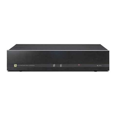
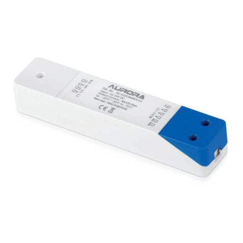
epixsky ADVANCED PRO RS232 Series User manual

page 1
epiXsky - Advanced Pro Product Manual
ADVANCED PRO RS232 SERIAL LED CONTROLLER
Specifications
Power Requirements
Operating Voltage
Input: 12-24VDC
Output: 4 Independent channels @12-24 VDC (same as voltage supplied)
Channel Current
10 A - 12 VDC (120W) per channel
5 A - 24 VDC (120W) per channel
Recommended Wiring
Technical Diagram
Dimensions
Length: 6” - 6" (153 mm)
Width: 4.1875" (6.7 mm)
Height: 1.45”
Weight: 1 lb.
Product Layout
Communication Interface
Test/Stand-Alone Mode
To run the controller in test/stand-alone mode, you will use the two
‘Mode Buttons’ (See pg. 2 for functions).
The controller will respond to the last command given either via RS232
or a button press. When the controller is powered off then on, it will resume the
last command it was given.
18 AWG up to 5 amps total
16 AWG up to 10 amp total
12 AWG up to 20 amp total
10 AWG up to 40 amp total (See Pg. 5 for more details)
TX RX GND
RS 232 5V WiFi
Power Output
WBGR
++
WHIT
OUTPUT
E RGB ADDRESS
LED OUTPUT
L 3 2 1 3 2 1 0
1.125”
28.5 mm
1.125”
mm28.5
FRONT
MODE
1
MODE
2
RS-232 OUT RS-232 IN
12V - 24V
+--
INPUT
BACK
advanced-pro
21
TX RX GND
RS 232
RS 232 OUT RS 232 IN
MODE
5V WiFi
Power Output
OUTPUT
WHITE RGB WBGR
++
+
12V-24V
--
LED OUTPUT INPUT
ADDRESS OPTION LOGO
0 1 2 3 1 2 3 L
6”
153mm
4.1875”
6.7 mm
PRODUCT MANUAL
epiX Hub:
-epiX Star Control App - WiFi or Bluetooth - Available at Apple and Android
App Stores
Serial RS232 from third party control system (Control 4, Crestron, Etc.)
9600 Baud, 8 Data Bits, no parity,
no handshaking, no flow control
2400 Baud, 8 data bits, no parity,
no handshaking, no flow control

page 2
Serial Commands
epiXsky - Advanced Pro Product Manual
Dip Switch Settings
Mode Button Actions - Stand-Alone Operation
Mode Button 1:
Mode Button 1 is used to switch through color modes of the controller. With no
RGB
LED channels on, a quick press of Mode Button 1 quickly (less than 1/2 a second)
will cycle through the solid colors. The color order is: red, green, blue, magenta,
cyan, gold, and
(RGB) white. Color cycling will start after the solid colors. Once color cycling
starts, a quick press of Mode Button 1 will pause the RGB Color Changing Cycle
and the color showing when paused will remain on. A quick press of Mode Button
1 will then start the RGB Color Changing Cycle again.
A long press of Mode Button 1 (more than 1/2 second) will result in the RGB
channels fading to off. This will work for solid colors as well as the color mode.
Mode Button 2:
Mode Button 2 is used for 2 purposes. If the controller is in RGB Color Changing
Cycle mode, this will increase the speed of the RGB Color Changing Cycle. The
RGB Color Changing Cycle has 10 selectable speeds. The default speed is 5. A
quick press of Mode Button 2 while in RGB Color Changing Cycle mode will result
in the speed increasing by 1. The logo will pulse the speed number you have
selected. When the speed is on 10 and a quick press of Mode Button 2 is done,
the speed will go to 1.
A long press (more than 1/2 second) of Mode Button 2, while in RGB Coloring
Cycle mode, will reset the speed to the default (5).
White Led Channel Mode:
A short press (less than 1/2 second) of Mode Button 2, while not in RGB Color
Changing Cycle mode, will increment the white LED channel by 10%. When the
white LED channel has reached 100%, and a short press of Mode Button 2 is
performed, the logo will pulse 1 time to indicate the white LED channel is at 100%.
A long press (more than 1/2 second) of Mode Button 2, while not in RGB Color
Changing Cycle mode, will fade the white LED channel to off if it is on. If a long
press of Mode Button 2 is performed while the white LED channel is off, the white
LED channel will fade up to 100%.
Address Switches 0-3:
The Address Switches are used to specify the address of the controller to be able
to run up to 8 of the controllers on one serial communication line. Please see
“Addressing the Controller” on page 4 for more detailed instructions.
Option Switches 1-3:
For future expansion of features on the controller.
Logo Switch:
If this switch is on, the blue glow of the logo will light up and pulse
with certain Mode Button presses. If the switch is off, it will remain unlighted.
After changing any dip switch settings, the controller must be power cycled (off
then on) for any of the changes to take affect.
Serial Format:
The serial format is 9600 baud, 8 bits, no parity, 1 stop bit, and no flow control.
The default baud rate is 9600, but you can change it to 2400 baud rate by
pressing both Mode Buttons while powering up the controller. The same
procedure switches it back. When the baud rate changes (and the ‘L’ dip switch is
on), the Logo LED will flash 2 times when switching to 2400, and 9 times when
switching to 9600. Once the baud rate has been changed, it will remain even if
powered off.
All commands require a “carriage return” <CR>. All commands are lowercase and
with no spaces.
Color Commands:
The color commands are in 3 parts, address, color, and level. The command
'xredyyy<CR>' is the command for setting the red level. x represents the address
of the unit, red represents the color, and y represents the desired LED level from 0
to 100. For example if you wanted to set the red level to 63% on a controller with
the address of 4, you would send the command, '4red63<CR>'. This command is
valid for red, green, blue, and white.
All White Mode:
The controller may be set up with white LED's on all 4 channels. The channels are
labeled on the board and share the color channels, White 1 with White, White 2
with Blue, White 3 with Green, and White 4 with Red. You can control the white
channels by using the optional white commands. The command is the address,
followed by wht followed by the channel, followed by a level. For example, if you
wanted to set White 3 to level 40% on a controller with the address of 7, you
would send the command '7wht340<CR>'. Firmware 2.7 will return “White 3 40%”,
while firmware 2.9 will return “#grn40”.
Preset Color Commands:
The preset color commands are for preset solid colors. To activate a solid color,
the command is the address, followed by the color. For example, if you wanted to
set the color pink on a controller with the address of 2, you would send the
command, '2pink<CR>'. The following list are the solid colors and commands.
Color:
Red
Green
Blue
Magenta
Cyan
Gold
RGB White
Orange
Light Blue
Light Green Violet
Pink
RGB Warm White
Command:
allred
allgreen
allblue
magenta
cyan
gold
rgbwhite
orange
ltblue
ltgreen
violet
pink
rgbww

page 3
epiXsky - Advanced Pro Product Manual
Serial Commands (cont.)
RGB Color Changing Cycle:
Preset Color Shows:
RGB Color Changing Cycle Pause:
Rate:
Ramp:
Bright (firmware 2.7):
Bright (firmware 2.9):
Dim:
All Led’s Off:
Global Off:
RGB Off (firmware 2.9):
The command for turning all LED's off is 2 parts, the address and the
alloff command. For example, if you wanted to turn all LED's off on a controller
with the address of 5, you would send the command, '5alloff<CR>'.
This command will turn off all LED's on all controllers connected,
regardless of it's address. The command is, 'globaloff<CR>'.
This command will turn off R, G, and B channels and leave the white
channel as is. For example, if you wanted to turn off all RGB channels on a
controller with the address of 2, you would send the command, '2rgboff<CR>'.
The command for starting a controller into the RGB Color Changing Cycle
mode is the address, followed by 'cycle'. For example, if you wanted to start the RGB
Color Changing Cycle mode on a controller with the address of 3, you would send the
command, '3cycle<CR>'.
If you want to change the rate or speed of the RGB Color Changing Cycle,
you would send the address, then a value from 0 to 255. The fastest change rate
is 0 and the slowest would be 255. For example, if you wanted to set the rate to 2
on a controller with the address of 7, you would send the command, '7rate2<CR>.
The default rate is preset to 4.
This command selects the ramp rate when the LED's change brightness
levels. The fastest rate is 0 and goes up to 255. To change the ramp value, you
would send the address, then 'ramp', then the ramp value. For example, if you
wanted to change the ramp rate to 6 on a controller with the address of 2, you
would send the command,
'2ramp6<CR>'. The default ramp value is preset to 4.
This command brightens the red, green, and blue LED's on a controller.
To use the bright feature, you would send the address, and then 'bright'. For
example, if you wanted to brighten the RGB LED's on a controller with the
address of 7, you would send the command,
'7bright<CR>'. LED's will be brightened separately, and once any color reaches
100%, it will remain at 100% with each additional bright command.
This command brightens the red, green, and blue LED's on a controller.
To use the bright feature, you would send the address, and then 'bright'. For
example, if you wanted to brighten the RGB LED's on a controller with the
address of 7, you would send the command,
'7brt<CR>'. LED's will be brightened separately, and once any color reaches
100%, it will remain at 100% with each additional bright command.
This command dims the red, green, and blue LED's on a controller. To
use the dim feature, you would send the address, and then 'dim'. For example, if
you wanted to dim the RGB LED's on a controller with the address of 4, you
would send the command, '4dim<CR>'. LED's will be dimmed separately, and
once any color reaches 0%, it will remain at 0% with each additional dim
command.
The command for starting a controller into a preset color show is the
address, followed by the show command. For example, if you wanted to start
the color show
“Tranquility” on a controller with the address of 3, you would send the
command,
'3ocean<CR>'.
The following list is the available shows, their commands, and their
colors.
Show:
Sunset
Tranquility
Morning Sky
Valentine
Easter
Christmas
Autumn
Royal
Romance
USA
Twilight
Rainbow
Mardi Gras
Cool Caberet
Command:
sun
ocean
sky
val
east
xmas
atm
royal
love
usa
twilight
rainbow
party
disco
Colors:
Orange, Gold, and RGB White
Blue, Light Blue, and Light Green
Light Blue and RGB White
Red, Pink, and White
Pink, Gold, and Cyan
Red and Green
Orange and Violet
Pink and Violet
Red, Pink, and White
Red, White, and Blue
Orange, Gold and RGB White
All - slow
All - Medium
All – Fast
Serial Commands (cont.)
To pause the RGB Color Changing Cycle mode on a certain color, send the
address followed by 'pause'. For example, if you wanted to pause the RGB Color
Changing Cycle mode on a controller with the address of 6, you would send the
command, '6pause<CR>'. This does not work with preset Show modes.

page 4
epiXsky - Advanced Pro Product Manual
Serial Commands (cont.)
WB
G
R
Serial Commands (cont.)
= Switch is up.
= Switch is down.
R, G, and B Bright & Dim Commands (firmware 2.9):
You can brighten R, G, and B channels by 2.5% with the commands, “btr”, “btg”,
and “btb” respectively. You can also dim the R, G, and B channels by 2.5% with
the commands,
“dmr”, “dmg”, and “dmb”. They also must have the address prefix in the
command as well. So if you are working with a controller with the address of 1
and you wanted to dim the red channel and brighten the blue channel, you would
send the commands, "1dmr" and "1btb".
Status Command:
You can query the status of a controller by sending the command
"status" (Firmware 2.7) or "stat" (Firmware 2.9). This command will return the
levels of all channels and the ramp rate.
Address Query:
You can send the command “address”(firmware 2.7) or
“addr” (firmware 2.9) and the controller will return the address that it is set to.
For a comprehensive list of commands, please see the
Advanced Command Sheet for the firmware version of your
controller at:
https://www.epixsky.com/specification-literature/
Addressing the Controller:
Address Switches 0-2 are used to set the controllers address. Each switch
represents a value, and the sum of all the value is the address. Switch “0”
represents 1, Switch “1” represents 2, and Switch “2” represents 4. So if you had
Switches “0 & 2” on, the address would be 5. The controllers default address is 0,
and that is by having no switches on. Address Switch 3 is not used at this time.
After changing any dip switch settings, the controller must be
power cycled (off then on) for any of the changes to take affect.
Use the examples below to help address your controller
321
3210
L
Address 0
Address
Logo Option
321
3210
L
Address 1
Address
Logo Option
321
3210
L
Address 2
Address
Logo Option
321
3210
L
Address 3
Address
Logo Option
321
3210
L
Address 4
Address
Logo Option
321
3210
L
Address 5
Address
Logo Option
321
3210
L
Address 6
Address
Logo Option
321
3210
L
Address 7
Address
Logo Option

page 5
epiXsky - Advanced Pro Product Manual
Qualifying Your Automation System
The Advanced Pro is designed to be controlled via RS-232 serial
communication. If your system can output ASCII text strings via an RS-232 port,
you can control our products. The RS-232 format is 8N1, or 8 data bits, no parity,
and 1 stop bit. This format is standard on many devices. (more details on pg. 2)
NOTE REGARDING AUTOMATION SYSTEM DRIVERS:
As we are a lighting company, we supply lighting controllers, but not the
drivers for them. We do not have access to the control systems, so we cannot
create or test drivers. Commands are all ASCII text strings and are straight
forward. If you can create a button on your automation system that sends an ASCII
text string out of a serial port, you can control the Advanced Pro
Control4 drivers are now available on their website.
You can download them here ---> Download Control4 drivers - EpiXsky
Disclaimer: We are not responsible for the operation, updating, or support of
these drivers.
All equipment is tested and inspected before shipment.
All secondary parts warranties are carried by their respective manufacturers with typical industry standard warranty
periods.
Buyer must inspect goods for any defects prior to installation, within 10 days of receipt. No claims will be accepted
after 10 days. All goods must be installed and inspected by a qualified installer or electrician, as appropriate
for the product. Impact Lighting, Inc. warrants its products to be free from defects in material and workmanship for
one year from date of purchase. This warranty is limited to the correction of any such defect or the replacement of the
defective item. This warranty does not cover labor, shipping or installation costs, and specifically excludes any product
that has suffered from misuse, negligence or accident, has been used in a manner contrary to accepted normal use or
to Impact Lighting, Inc.'s printed instructions, if any, or been improperly installed, overloaded, altered, tampered with,
or otherwise abused or in which any parts, including glass, have been reworked, repaired, or replaced outside of
Impact Lighting, Inc's facility. This warranty specifically excludes finishes due to the unsuitability of many cleaning
agents. There are no other express warranties including any warranty of merchantability or fitness for particular
purpose. Impact Lighting, Inc. shall not be liable for consequential damages or cost of removal and reinstallation of its
products. This warranty is strictly limited to the original purchaser.
Basic Wiring Diagram
*Always follow wiring instructions for your specific LED
product. Always match the +,R,G,B wires from your product
to the corresponding terminals on the Advanced-Pro
Table of contents
