NI cRIO-9012 User manual

USER MANUAL AND SPECIFICATIONS
NI cRIO-9012/9014
Intelligent Real-Time Embedded Controllers for CompactRIO
Figure 1. CompactRIO cRIO-9012/9014
1
83
5
7
4
6
2
1. LEDs
2. SMB Connector
3. Power Connector
4. DIP Switches
5. Reset Button
6. RJ-45 Ethernet Port
7. USB Port
8. RS-232 Serial Port
This document describes how to connect the cRIO-9012/9014 to a network and how to use the
features of the cRIO-9012/9014. This document also contains specifications for the
controllers.
Safety Guidelines for Hazardous Locations
The cRIO-9012/9014 is suitable for use in Class I, Division 2, Groups A, B, C, D, T4
hazardous locations; Class I, Zone 2, AEx nA IIC T4 and Ex nA IIC T4 hazardous locations;
and nonhazardous locations only. Follow these guidelines if you are installing the
cRIO-9012/9014 in a potentially explosive environment. Not following these guidelines may
result in serious injury or death.
Caution Do not disconnect the power supply wires and connectors from the
controller unless power has been switched off.
Caution Do not install or remove the controller unless power has been switched
off.
Caution Substitution of components may impair suitability for Class I, Division 2.
Caution For Division 2 and Zone 2 applications, install the system in an enclosure
rated to at least IP54 as defined by IEC/EN 60079-15.
Special Conditions for Hazardous Locations Use in
Europe and Internationally
The cRIO-9012/9014 has been evaluated as Ex nA IIC T4 Gc equipment under DEMKO
Certificate No. 03 ATEX 0324020X and is IECEx UL 14.0089X certified. Each
cRIO-9012/9014 is marked II 3G and is suitable for use in Zone 2 hazardous locations, in
ambient temperatures of -40 °C ≤ Ta ≤ 70 °C. If you are using the cRIO-9012/9014 in Gas
Group IIC hazardous locations, you must use the device in an NI chassis that has been
evaluated as Ex nC IIC T4, Ex IIC T4, Ex nA IIC T4, or Ex nL IIC T4 equipment.
Caution You must make sure that transient disturbances do not exceed 140% of
the rated voltage.
Caution The system shall only be used in an area of not more than Pollution
Degree 2, as defined in IEC 60664-1.
Caution The system shall be mounted in an ATEX/IECEx-certified enclosure with
a minimum ingress protection rating of at least IP54 as defined in IEC/EN 60079-15.
Caution The enclosure must have a door or cover accessible only by the use of a
tool.
Electromagnetic Compatibility Guidelines
This product was tested and complies with the regulatory requirements and limits for
electromagnetic compatibility (EMC) stated in the product specifications. These requirements
and limits provide reasonable protection against harmful interference when the product is
operated in the intended operational electromagnetic environment.
This product is intended for use in industrial locations. However, harmful interference may
occur in some installations, when the product is connected to a peripheral device or test object,
or if the product is used in residential or commercial areas. To minimize interference with
2| ni.com | NI cRIO-9012/9014 User Manual and Specifications

radio and television reception and prevent unacceptable performance degradation, install and
use this product in strict accordance with the instructions in the product documentation.
Furthermore, any changes or modifications to the product not expressly approved by National
Instruments could void your authority to operate it under your local regulatory rules.
Special Conditions for Marine Applications
Some products are Lloyd’s Register (LR) Type Approved for marine (shipboard) applications.
To verify Lloyd’s Register certification for a product, visit ni.com/certification and search for
the LR certificate, or look for the Lloyd’s Register mark on the product.
Caution In order to meet the EMC requirements for marine applications, install the
product in a shielded enclosure with shielded and/or filtered power and input/output
ports. In addition, take precautions when designing, selecting, and installing
measurement probes and cables to ensure that the desired EMC performance is
attained.
Installing the Controller on the Chassis
The following figure shows the dimensions of the cRIO-9012/9014.
NI cRIO-9012/9014 User Manual and Specifications | © National Instruments | 3

Figure 2. cRIO-9012/9014, Front and Bottom View with Dimensions
77.3 mm
(3.04 in.)
90.2 mm
(3.55 in.)
44.2 mm
(1.74 in.)
88.1 mm
(3.47 in.)
44.2 mm
(1.74 in.)
1
1. M4 Thread
Complete the following steps to install the controller on the chassis.
1. Make sure that no power is connected to the controller or the chassis.
2. Align the controller with the chassis as shown in the following figure.
4| ni.com | NI cRIO-9012/9014 User Manual and Specifications

Figure 3. Installing the cRIO-9012/9014 in the Chassis
1
4
3
2
1. Controller
2. Captive Screws
3. Controller Slot
4. Reconfigurable Embedded Chassis
3. Slide the controller onto the controller slot on the chassis. Press firmly to ensure the
chassis connector and the controller connector are mated.
4. Using a number 2 Phillips screwdriver, tighten the two captive screws on the front of the
controller to 1.3 N · m (11.5 lb · in.) of torque.
Connecting the Controller to a Network
Connect the controller to an Ethernet network using the RJ-45 Ethernet port on the controller
front panel. Use a standard Category 5 (CAT-5) or better shielded, twisted-pair Ethernet cable
to connect the chassis to an Ethernet hub, or use an Ethernet crossover cable to connect the
chassis directly to a computer.
Caution To prevent data loss and to maintain the integrity of your Ethernet
installation, do not use a cable longer than 100 m. If you are using 100 Mbps
Ethernet, National Instruments recommends using a CAT-5 or better shielded
twisted-pair Ethernet cable.
If you need to build your own cable, refer to the Cabling section for more information about
Ethernet cable wiring connections.
The host computer communicates with the controller over a standard Ethernet connection. If
the host computer is on a network, you must configure the controller on the same subnet as the
NI cRIO-9012/9014 User Manual and Specifications | © National Instruments | 5

host computer. If neither the host computer nor the CompactRIO controller is connected to a
network, you can connect the two directly using a crossover cable.
If you want to use the controller on a subnet other than the one the host computer is on, first
connect the controller on the same subnet as the host computer. Use DHCP to assign an IP
address or reassign a static IP address for the subnet where you want it to be and physically
move it to the other subnet. The first time you configure the controller, you must also install
software on it. Refer to the Measurement & Automation Explorer Help for more information
about configuring the controller in Measurement & Automation Explorer (MAX). Contact
your network administrator if you need assistance configuring the host computer and
controller on the same subnet.
Wiring Power to the Controller
Caution You must install the controller on a CompactRIO chassis and tighten the
captive screws before you apply power to the controller. Installing the controller
while power is applied to it can cause damage to the chassis.
The cRIO-9012/9014 requires an external power supply that meets the specifications in the
Power Requirements section. The cRIO-9012/9014 filters and regulates the supplied power
and provides power for all of the I/O modules in the chassis. You must connect a power supply
to at least one pair of V and C terminals. Optionally, you can connect a power supply to the
other pair of V and C terminals. The controller draws power from the power supply with the
higher voltage. The cRIO-9012/9014 has one layer of reverse-voltage protection. Complete the
following steps to connect a power supply to the chassis.
1. Connect the positive lead of the power supply to the V1 or V2 terminal of the power
connector shipped with the cRIO-9012/9014, and tighten the terminal screw. The
following figure shows the terminal screws, which secure the wires in the screw
terminals, and the connector screws, which secure the power connector on the controller.
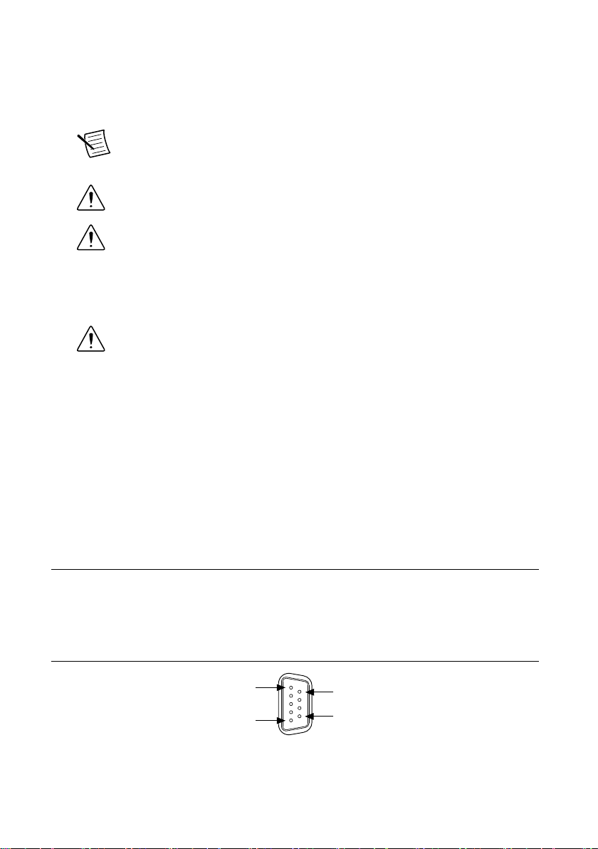
Figure 4. Power Connector
C
V2
C
V1
2
1
2
1. Terminal Screws
2. Connector Screws
2. Connect the negative lead of the power supply to one of the C terminals of the power
connector and tighten the terminal screw.
6| ni.com | NI cRIO-9012/9014 User Manual and Specifications
3. Optionally, you can connect the positive lead of another power supply to the other V
terminal and the negative lead to one of the C terminals. You must install the ferrite
across both pairs of wires.
4. Install the power connector on the front panel of the cRIO-9012/9014 and tighten the
connector screws.
Note The controller draws power from either V1 or V2 depending on which
terminal has a higher voltage. It does not draw power from both terminals. The
controller switches between V1 and V2 without affecting operation.
Caution The C terminals are internally connected to each other. If you use
two power supplies, make sure that they share a common ground.
Caution The C terminals are internally connected to the controller chassis to
prevent a faulty ground connection from causing the chassis ground to float. If
you reverse the input voltage, the positive input voltage is connected directly to
the chassis. The controller has built-in reversed-voltage protection, but reversed
voltage can damage connected peripherals if the chassis ground is not reliably
connected to earth ground.
Caution Do not tighten or loosen the terminal screws on the power connector
while the power connector is plugged into the controller or while the power
supply is on.
Powering On the cRIO-9012/9014
When you apply power to the cRIO-9012/9014, the controller runs a power-on self test
(POST). During the POST, the Power and Status LEDs turn on. The Status LED turns off,
indicating that the POST is complete.
You can configure the cRIO-9012/9014 to launch an embedded stand-alone application each
time you boot the controller.
Connecting Serial Devices to the
cRIO-9012/9014
The cRIO-9012/9014 has an RS-232 serial port to which you can connect devices such as
displays or input devices. Use the Serial VIs to read from and write to the serial port from a
LabVIEW Real-Time application. For more information about the Serial VIs, refer to the
LabVIEW Help.
Figure 5. Controller Serial Port
Pin 1
Pin 5
Pin 6
Pin 9
NI cRIO-9012/9014 User Manual and Specifications | © National Instruments | 7

Table 1. DB-9 Pin Descriptions
Pin Signal
1 DCD
2 RXD
3 TXD
4 DTR
5 GND
6 DSR
7 RTS
8 CTS
9 RI
Using the Internal Real-Time Clock
The system clock of the cRIO-9012/9014 is synchronized with the internal high-precision real-
time clock at startup. This synchronization provides timestamp data to the controller. For
information about using the internal real-time clock to correct drift of the system clock, go to
ni.com/info and enter the Info Code crioclock. Refer to the Specifications section for the
accuracy specifications of the real-time clock.
Using the SMB Connector for Digital I/O
You can use the SMB connector of the cRIO-9012/9014 to connect digital devices to the
controller. For example, if you connect the pulse-per-second output of a GPS device to the
SMB connector of the cRIO-9012/9014, you can use the GPS device to correct for drift of the
system clock.
For software that supports GPS drift-correction and other digital I/O through the SMB
connector, go to ni.com/info and enter the Info Code criosmb.
Connecting USB Mass-Storage Devices to the
Controller
The cRIO-9012/9014 supports common USB mass-storage devices such as USB Flash drives
and USB-to-IDE adapters formatted with FAT16 and FAT32 file systems. Storage size is
limited only by the file system. The cRIO-9012/9014 does not support other types of USB
devices. You can connect USB mass-storage devices to the cRIO-9012/9014 while the
controller is operating. In order to avoid data loss or corruption, do not connect or disconnect
8| ni.com | NI cRIO-9012/9014 User Manual and Specifications

USB mass-storage devices while the controller is communicating with them. USB devices are
mapped to the U: drive in LabVIEW.
Configuring DIP Switches
Figure 6. DIP Switches
SAFE MODE
CONSOLE OUT
IP RESET
NO APP
USER1
ON OFF
All of the DIP switches are in the OFF position when the chassis is shipped from National
Instruments.
SAFE MODE Switch
The position of the SAFE MODE switch determines whether the embedded LabVIEW Real-
Time engine launches at startup. If the switch is in the OFF position, the LabVIEW Real-Time
engine launches. Keep this switch in the OFF position during normal operation. If the switch is
in the ON position at startup, the cRIO-9012/9014 launches only the essential services
required for updating its configuration and installing software. The LabVIEW Real-Time
engine does not launch.
If the software on the controller is corrupted, you must put the controller into safe mode and
reformat the controller drive. You can put the controller into safe mode by powering it up
either with the SAFE MODE switch in the ON position or with no software installed on the
drive. Refer to the Measurement & Automation Explorer Help for more information about
installing software on a controller and reformatting the drive on the controller.
CONSOLE OUT Switch
With a serial-port terminal program, you can use the CONSOLE OUT switch to read the IP
address and firmware version of the controller. Use a null-modem cable to connect the serial
port on the chassis to a computer. Push the switch to the ON position. Make sure that the
serial-port terminal program is configured to the following settings:
• 9,600 bits per second
• Eight data bits
• No parity
• One stop bit
• No flow control
The serial-port terminal program displays the IP address and firmware version of the
controller, and alerts you when you connect an unsupported USB device to the controller.
Keep this switch in the OFF position during normal operation.
NI cRIO-9012/9014 User Manual and Specifications | © National Instruments | 9

IP RESET Switch
Push the IP RESET switch to the ON position and reboot the controller to reset the IP address
and other TCP/IP settings of the controller to the factory defaults. Refer to the Troubleshooting
Network Communication section for more information about resetting the IP address. You also
can push this switch to the ON position to unlock a chassis that was previously locked in
MAX.
NO APP Switch
Push the NO APP switch to the ON position to prevent a LabVIEW Real-Time startup
application from running at startup. If you want to permanently disable a LabVIEW Real-Time
application from running at startup, you must disable it in LabVIEW. To run an application at
startup, push the NO APP switch to the OFF position, create an application using the
LabVIEW Application Builder, and configure the application in LabVIEW to launch at
startup. If you already have an application configured to launch at startup and you push the
NO APP switch from ON to OFF, the startup application is automatically enabled. For more
information about automatically launching VIs at startup and disabling VIs from launching at
startup, refer to the LabVIEW Help.
USER1 Switch
You can define the USER1 switch for your application. To define the purpose of this switch in
your embedded application, use the RT Read Switch VI in your LabVIEW Real-Time
embedded VI. For more information about the RT Read Switch VI, refer to the LabVIEW
Help.
Using the RESET Button
Pressing the RESET button resets the processor in the same manner as cycling power.
Understanding LED Indications
Figure 7. cRIO-9012/9014 LEDs
1 2 3 4
1. POWER
2. FPGA
3. STATUS
4. USER1
POWER LED
The POWER LED is lit while the cRIO-9012/9014 is powered on. This LED indicates that the
power supply connected to the chassis is adequate.
10 | ni.com | NI cRIO-9012/9014 User Manual and Specifications
This manual suits for next models
1
Table of contents
Other NI Controllers manuals


Popular Controllers manuals by other brands

Digiplex
Digiplex DGP-848 Programming guide

YASKAWA
YASKAWA SGM series user manual

Sinope
Sinope Calypso RM3500ZB installation guide

Isimet
Isimet DLA Series Style 2 Installation, Operations, Start-up and Maintenance Instructions

LSIS
LSIS sv-ip5a user manual

Rockwell Automation
Rockwell Automation 1769-L31 installation instructions


