Amrel PPS-1326 User manual

1
ONE: INTRODUCTION
Congratulations! You have just purchased one of the most advanced professional Programmable Power Supplies
available. The innovative ergonomic design and overall high quality will provide years of reliable operation.
Therefore, it is very important to completely familiarize yourself with the unit before attempting use. Please read
this manual carefully, paying particular attention to the Warning and Caution sections.
At this time, please fill out the warranty card with all the applicable information and return to American
Reliance. The completed warranty card will ensure the benefits of a three-year warranty. We at American
Reliance, thank you for your selection of one of our products and welcome you to the family of American Reliance
product owners. Remember that, at American Reliance service does not end upon your purchase, it is just
beginning. If you have any questions, please do not hesitate to call our toll-free technical support line at (800) 654-
9838.
1.1 DESCRIPTION
The Programmable Power Supply Series from American Reliance Inc. offers a complete solution to power supply
system requirements. These models are indispensable instruments in assisting in the development and testing of
new products, as well as being standard instruments for automatic test systems. The wide range of output selection
combined with excellent load/line regulation creates a vital instrument in your lab environment.
The PPS Series come standard with a GPIB interface and a three-year warranty. Plus, all units come standard with
output voltage and current programming, overvoltage and overcurrent protection, remote sense, reverse polarity
protection and output enable/disable. All models of the programmable power supply series are able to be calibrated
either in local or remote mode.
1.2 INSPECTION
When you unpack your new programmable power supply from its original packaging, carefully check each item for
damage that may have occurred during shipment. If anything is damaged or missing, please contact American
Reliance at (818) 303-6688 for immediate service.
1.3 INCLUDED ITEMS
Programmable Power Supply
Operation Manual
Power Cord
1.4 CAUTIONS AND WARNINGS
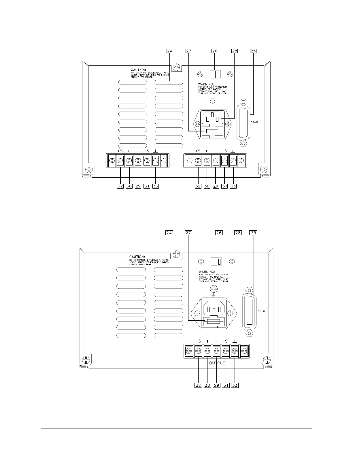
1. The input power requirements for the programmable power supplies are 115/230 VAC ±10% or 240VAC
±10%, 50/60 Hz.
2. Before begin to operate the power supply, set the correct voltage 115 or 230(240) VAC setting equal to the
applied voltage, otherwise damage will result to the power supply.
3. Do not use solvents or aromatic hydrocarbons to clean the module as they may damage the finish. If cleaning
is necessary, use only a mild solution of soap and warm water. Be careful not to allow water to enter the unit.
Please be sure to always disconnect the power cord before cleaning.
4. Use only specified fuses. Do not use a substitute fuse which is of a different size and rating. Otherwise, damage
may result to the unit.
5. Do not substitute or modify any internal circuits.

2
6. Exercise extreme caution when cables are over four feet in length.
7. Turns off AC power (or disable unit) before disconnecting load or floating voltages.
8. Operates the power supply with properly rated wire sizes.
1.5 LOCATION AND COOLING
1. The proper operating temperature for the power supply are from 0°C to 50°C. The unit ventilates by drawing
air through the sides and exhausting it through the rear.
2. Proper ventilation area for the power supplies is at least 1" of spacing on all sides.
3. The PPSs are built to configure into 1/2 rack mount configurations.
1.6 GPIB INTERFACE CONNECTOR
The GPIB connector on the rear panel connects your supply to the computer and other GPIB devices. A GPIB
system can be connected in any configuration (star, linear, or both) as long as the following rules are observed:
1) The total number of devices including the computer should not be greater than 15.
2) The total length of all cables used should not be more than 2 meters times the number of devices connected
together, or a maximum length of 20 meters.
Please do not stack more than three connector blocks together on any GPIB port. The resulting leverage can exert
excessive force on the mounting panels. Make sure that all connectors are fully seated and that the lock screws are
firmly hand tightened. Use a screwdriver only when removing the screw from the mounting panels.

3
TWO: GETTING STARTED
2.1 UNIT FAMILIARIZATION
Use the following illustrations of the power supplies in conjunction with the descriptions to familiarize yourself
with the unit.
Front Panel: Figure A, B, C, D
ENTER
OVP BEEP
UTILITY
SELECT
êê
éé
çç èè
OUTPUT
21
18
22
23
30.00V 0.000A
CC
RMT OVP
OCP
High
Figure A. Front Panel of PPS-1326
30.00V 0.000A
CC
RMT OVP
OCP
ENTER
OVP BEEP
UTILITY
SELECT
êê
éé
çç èè
OUTPUT
21
18
22
23
Figure B. Front Panel of PPS-1603/10710

4
ENTER
OVP BEEP CH
UTILITY
SELECT
TRK
10
êê
éé
çç èè
PROGRAMABLE DC POWER SUPPLY
FUNCTION/DATA ENTRY
1.002V 0.000A OVPRMT
CC OCP
20
2
Figure C. Front Panel of PPS-1322/1302A
ENTER
OVP BEEP CH
UTILITY
SELECT
TRK
10
êê
éé
çç èè
PROGRAMABLE DC POWER SUPPLY
FUNCTION/DATA ENTRY
CH 2CH 1
1.002V*0.000A OVP1
OVP2TRK
RMT
CC2
CC1 OCP1
OCP2
0.999V 0.000A
Figure D. Front Panel of PPS-2322

5
2.1.1 FRONT PANEL KEYS
NOTE: Most soft keys have two functions. The first function of the keys is function entry (i.e. VSET, ISET,
OCP etc.). The second function for the soft keys is numeric data entry (i.e. 0-9).
1. LCD Display Displays alphanumeric information with status annunciators. A detailed listing
of descriptions is presented in section LCD STAUS ANNUNCIATORS
2. Power On/Off Powers on the unit.
3. Negative Terminal Negative output terminal.
4. Ground Terminal Ground output terminal.
5. Positive Terminal Positive output terminal.
6. -S Terminal Negative remote sense (Applicable only for the PPS-1326/1603/10710)
7. +S Terminal Positive remote sense (Applicable only for the PPS-1326/1603/10710)
8. VSET (7) Output control key used to display or alter the present voltage setting. Numeric
entry key for number seven.
9. ISET (8) Output control key used to display or alter the present current setting. Numeric
entry key for number eight.
10. TRK (9) Mode control key which activates the tracking mode on or off. (Applicable only
for the PPS-2322 ). Numeric entry key for number nine.
11. LCL (CLEAR) Used in conjunction with the numeric entry keys to clear partially set
commands and returns unit to the metering mode. Also returns the supply to
Local mode when the unit is operating in the Remote mode.
12. OVSET (4) Output control key used to display or alter the overvoltage threshold. Numeric
entry key for number four.
13. OCP (5) Mode control key which activates the "OverCurrent Protection" mode on or off.
Numeric entry key for number five.
14. ADDR (6) System control key used to view or alter the GPIB address. Addresses available
are 0-30. Numeric entry key for number six.
15. OUTPUT (ON/OFF) Mode control key which activates the output on or off. When the output is
disabled, the LCD displays "OUTPUT OFF".
16. OVP (1) Mode control key which activates the "OverVoltage Protection" mode on or off.
Numeric entry key for number one.
17.
é
(2) This key increases the value of the digit to be varied.
Numeric entry key for number 2

6
.
18. BEEP (3) Activates the audible indicator on or off. Numeric entry key for number three.
19.
ç
(0) This key moves the cursor one digit left until it comes to the desired
digit to be varied. Numeric entry key for "0".
20. ê(.)This key decreases the value of the digit to be varied.
Decimal point key.
21. èThis key moves the cursor one digit right until it comes to the digit to be
varied.
22. CH ( SELECT ) This key allows you to select channel 1 or channel 2 (Applicable only for the
PPS-2322 ).
23. UTILITY ( ENTER ) Reserved for future use. Enters the values in the setting mode and returns the
display to metering mode.
REAR PANEL: Figure E-1, E-2, E-3
Figure E -1. Rear Panel of PPS-1603/10710

7
OUTPUT
channel 1 OUTPUT
channel 2
Figure E -2. Rear Panel of PPS-2322
Figure E -3. Rear Panel of PPS-1322/1302A/1326

8
2.1.2 REAR PANEL
24. Ventilation ports -Exhausts warm air from the unit.
25. GPIB Interface -24 pin parallel GPIB interface connector.
26. Voltage Selector -Selects voltage of either 115VAC or 230(240)VAC, -10% ∼+10%, 50/60Hz.
27. Fuseholder -Fuseholder for AC line.
28. AC receptacle -AC plug for power cord.
29. Negative Terminal (-) -Negative rear screw terminal output for hard wiring.
30. Positive Terminal (+) -Positive rear screw terminal output for hard wiring.
31. -S-Negative rear screw terminal for remote sense output. Enables hard wiring.
32. +S -Positive rear screw terminal for remote sense output. Enables hard wiring.
33. Ground Terminal -ground rear screw terminal.
34. External analog input voltage for programming output voltage. Input voltage ranges from 0 Volts to 10 Volts.
35. Voltage external programming reference point.
36. External analog input voltage for programming output current. Input voltage ranges from 0 Volts to 10 Volts.
37. Current external programming reference point.
<NOTES:>
1. The rear panel configuration is identical on all power supplies. However, the PPS-2322 has an
additional terminal strip for hard wiring the second channel.
2. The PPS-1603 and the PPS-10710 have an external programming input terminal located at the
rear of the supply. Please refer to section 3.7 for further information.
2.2 LCD STATUS ANNUNCIATORS
LIQUID CRYSTAL DISPLAY: Figure F-1, F-2, F-3
OCP1
CC2 30.00V * 0.000A
1 5
CC1
TRK
RMT OVP1
OVP2
OCP2
INPUT ERROR!
2
3
4
6
7
8
9
Figure F -1. LCD of PPS-2322

9
OVP
OCP
RMT
CC 30.00V 0.000A
1
3
5
7
Figure F -2. LCD of PPS-1322/1302A/1603/10710
OVP
OCP
RMT
CC 30.00V 0.000A
1
3
5
7
High
10
Figure F -3. LCD of PPS-1326
<NOTE:>
The LCD displays real time output Voltage/Current & mode status.There are no status
indicators for CV mode. These messages are viewed in either local or remote mode.
1. CC1 -Channel 1 is operating under constant current mode.
2. CC2 -Channel 2 is operating under constant current mode. (Applicable only for the PPS-2322)
3. RMT -The supply is operating in remote mode.
4. TRK -The supply is operating in tracking mode. (Applicable only for the PPS-2322)
5. OCP1 -Overcurrent protection on channel 1 is enabled. When blinking, the overcurrent circuit
has been activated and disabled the output.
6. OCP2 -Overcurrent protection on channel 2 is enabled. When blinking, the overcurrent circuit
has been activated and disabled the output. (Applicable only for the PPS-2322)
7. OVP1 -Overvoltage protection on channel 1 is enabled. When blinking the overvoltage circuit
has been activated and disabled the output.
8. OVP2 -Overvoltage protection on channel 2 is enabled. When blinking the overvoltage circuit
has been activated and disabled the output. (Applicable only for the PPS-2322)
9. INPUT ERROR! The numeric value entered is out of range. (Applies to all models)
10. High or Low The supply is operating in either the high or low range. (Applicable only to the PPS-
1326)

10
2.3 OUTPUT TERMINALS AND WIRES
All models have terminal blocks on the rear panel which include positive and negative outputs, positive and
negative remote sense outputs, and earth ground.
<NOTE:>
The power supply is set at the factory for local sense operation (i.e. the +S and -S terminals are
strapped to the "+" and "-" terminals by a shorting plate at the rear terminal block). When
operating in remote sense mode, remove the shorting plate and refer to section 3.3 for remote
sense operation.
Additionally, all models have positive, negative and earth ground terminals in the front of the unit. Remote sense
capability is discussed in detail in section 3.3. A brief definition of remote sense is a measurement of voltage at the
load rather than at the output terminals.
Local connections are made to the "+" and "-" terminals of the power supply. Terminated loads only. Wrap and
bundle wires to reduce coupling effect.
In order to safely and sufficiently handle electric current, the proper wire size must be selected. Select a wire size
with sufficient rating to carry the current without overheating. Other factors to be taken into consideration are
voltage drop and conductor temperature.
The following table lists current carrying capacity of various wire sizes. For further information please refer to the
NEC 1987 Handbook.
TABLE 1: Stranded Copper Wire Ampacity and Resistivity.
Ampacity Per Wire (Amps)
Wire Size 2 Wire Bundle 4 Wire Bundle Resistivity
(AWG) (Amps) (Amps) (ohm/ft)
20 7.8 6.9 0.0102
18 14.5 12.8 0.0064
16 18.2 16.1 0.0040
14 29.3 25.9 0.0025
12 37.6 33.2 0.0016

11
THREE: OPERATING CHARACTERISTICS AND CONFIGURATIONS
3.1 INTRODUCTION
These sections contain information on operating characteristics and how to configure the PPS Series. Sections 3.2
through 3.4 consider the power supplies operating ranges, remote sense operation and considerations when
connecting loads.
The latter half of the chapter deals with connecting power supplies in parallel and series configuration for CC and
CV operation.
3.2 OPERATING RANGES
All power supplies operate in either constant voltage (CV) or constant current (CC) mode over the rated output .
Their respective voltage and current operating locus (figure F) are found in operating quadrants for all models. The
power supply acts as a constant voltage source for comparatively large values of load resistance and as a current
source for comparatively small values of load resistance. The automatic crossover or transition between these two
modes of operations occurs at a critical stage or "crossover" value of load resistance; Rc= Es/Is, where Esis the
front panel voltage setting and Isthe front panel current setting.
The followings are the operating quadrants (current -vs-voltage) of the power supplies.
V
I
V
I
V2 (Low)
V1 (High)
I1 (High) I2 (Low)
Vmax
Imax
PPS-1322/1302A/2322/1603/10710 PPS-1326
Figure G. Operating Quadrants

12
3.3 REMOTE SENSE
When the supply is locally strapped for local sensing (normal operation), an unavoidable voltage drop is incurred
in the load leads and this adds to its voltage regulation. By connecting the supply for voltage remote sensing, as
shown in figure G, voltage is sensed at the load rather than at the output terminals. This allows the supply to
automatically compensate for voltage drop in the load leads and improve regulation. In remote sensing, the
VOUT? query and the front panel meter monitor load voltage at the sensing points.
When the supply is connected for remote sensing, the OVP circuit senses at the main output terminal and not at the
sense points. The voltage sensed by the OVP circuit could be significantly higher than the voltage being regulated
at the load. Therefore, set OVP threshold voltage accordingly.
3.3.1 REMOTE SENSE CONFIGURATION
Turn off the power supply before modifying any connections on the rear panel terminal block. Configure the unit
for remote sensing by first disconnecting the shorting plugs between the sense and load terminals. Connect the load
and sense leads to the load as in figure G. Bear in mind that sense and load leads should be as short as possible.
Additionally, the sense leads resistance should be no greater than 0.5 ohm/lead, and the voltage drop over the load
leads should be no greater than 0.5V/lead.
Figure G. Remote Sense Configuration
3.3.2 REMOTE SENSE CHARACTERISTICS
OUTPUT NOISE: Any noise picked up on the sense leads will appear at the supply's output and may adversely
affect CV load regulation. Twist the sense leads to minimize external noise pickup and run them parallel and close
to the load leads. In noisy environments, it may be necessary to shield the sense leads. Ground the shield at the
power supply end only. Do not use the shield as one of the sensing conductors.

13
STABILITY: When the supply is connected for remote sensing, it is possible for the impedance of the load wires
and the capacitance of the load to form a filter, which will become part of the supply's CV feedback loop. The extra
phase shift created by this filter can degrade the supply's stability and can result in poor transient response
performance. In extreme cases, it can cause oscillation.
It is difficult to state simple rules defining the conditions under which this can occur, and which corrective action
to take. A certain amount of trial and error may be called for. Two guidelines which are almost always valid are:
a. Keep the leads as short as possible.
b. Twist the load leads together to minimize inductance.
In most circumstances, once these two guidelines are followed, problems associated with the load lead inductance
are eliminated. This leaves the load lead resistance and load capacitance as the major cause of the reduced stability.
In this case, you may obtain further improvement to the stability by:
a. Keeping the load capacitance as small as possible.
b. Increasing the diameter of the load lead to reduce resistance.
If heavier gauge load leads ( #10 or greater ) are used, circumstances may arise when the load lead inductance and
the load capacitance can form an underdamped filter. This filter occasionally has the effect of destabilizing phase
response. In this case, the above steps can worsen stability since they will reduce damping in the system.
3.4 LOAD CONSIDERATION AND MULTIPLE LOADS CONNECTION
When the supply is in local sensing mode and you are connecting multiple loads to the output, connect each load to
the output terminal using separate load leads. This minimizes mutual coupling effects and takes full advantages of
the supply's low output resistance. Each pair of wires should be as short as possible and twisted or bundled to
reduce lead inductance and noise pickup.
If cabling considerations require the use of distribution terminals that are located remotely from the supply,
connect the power supply output terminals to the remote distribution terminals by a pair of twisted or bundled
wires. Connect each load to the distribution terminals separately. Remote voltage sensing is recommended in these
circumstances. Sense either at the remote distribution terminals or, if one load is more sensitive than the others,
directly at the critical load.
OUTPUT ISOLATION: The output of the power supply is isolated from earth ground. Either output terminal may
be grounded, or an external source of voltage may be connected between either output and ground. However, both
output terminals must be kept within +/-240Vdc of ground. This includes the output voltage. An earth ground
terminal is provided on the rear panel terminal block.
Each of the power supplies will operate accordingly to the various types of loads connected to the output.
CAPACITANCE LOADING: In normal conditions, the supply will be stable for almost any size load capacitance
(for remote sense stability considerations). However, large load capacitance may cause ringing in the supply's
transient response. It is even possible that certain combinations of capacitance and ESR (equivalent series
resistance) will result in instability. If this is the case, the solution is to increase or decrease total load capacitance.
In addition, the overvoltage protection SCR crowbar circuit has been designed to discharge capacitance up to a
certain limit. These limits are:
1. For models with maximum output voltage below 32 Volts, Capacitance should not exceed 5000uF.

14
2. For models with maximum output voltage below 60 Volts, Capacitance should not exceed 3000uF.
<NOTE:>
If load capacitance approaches these limits, it is recommended to not intentionally activate
the OVP circuit and discharge the capacitance through the SCR crowbar as part of
standard testing procedure.
3.5 PARALLEL CONNECTION OPERATION
<NOTE:>
Power supplies equipped with SCR crowbars should not be used in series or parallel with
each other unless a master-slave interconnection is employed and their crowbars interlock.
Greater current capability can be achieved by connecting outputs in parallel. However, only power supplies
which have equivalent voltage and current output ratings may be connected in parallel. Otherwise, damage
to the unit may result.
A typical connection is shown in figure H through the back of PPS-2322 in local sensing. All leads are kept as
short as possible and are bundled together. Second, connect remote sense terminals to compensate for the voltage
drop in the interconnecting load leads. Lastly, the CV and CC operations have identical setups.
OUTPUT
channel 1 OUTPUT
channel 2
Figure H. Parallel Configuration
3.5.1 CV OPERATION
Although both outputs operate independently of each other in CV operation, one of the outputs must dominate
(control) over the other. Additionally, the dominant output must operate in CV mode, while the other output may
operate in CC mode.

15
As an example of this operation, let's assume in figure H. that output channel two operates in CC mode and output
channel one operates in CV mode. Perform the following steps:
1. Set output channel two to the maximum output voltage of desired range.
2. Set output channel one to the desired operating voltage.
The voltage of output channel one controls the voltage across the load. The output currents are algebraic sums of
the individual outputs.
3.5.2 CC OPERATION
The CC operation is similar in many ways to the CV operation, except that the output current must also be set. To
obtain CC operation, perform the following steps:
1. Program output voltage of the two channels to the desired operating voltage.
2. Program output channel one to one-half the desired operating current.
3. Program output channel two to one-half the desired operating current.
Both outputs operate in CC mode.
3.5.3 REMOTE SENSING CONFIGURATION (Parallel Connection Mode)
The following figure I illustrates the configuration for Remote Sensing in Parallel Operation.
OUTPUT
channel 1 OUTPUT
channel 2
Figure I. Remote Sense, Parallel Mode

16
3.6 SERIES CONNECTION OPERATION
<NOTE:>
Power supplies equipped with SCR crowbars should not be used in series or parallel with
each other unless a master-slave interconnection is employed and their crowbars interlock.
Greater output voltage capability can be obtained by connecting outputs in series. A note of caution, since current
is the same in each element of a series circuit, both outputs need identical rated currents. If this is not
followed, excessive current may be forced into one of the outputs and cause a failure.
Figure J illustrates the Series configuration on a PPS-2322.
OUTPUT
channel 1 OUTPUT
channel 2
Figure J. Series Configuration
3.6.1 CV OPERATION
In CV operation, first program the current of both outputs to the desired value. Secondly, program the desired
operating voltage to equal the sum of the output voltages.
3.6.2 CC OPERATION
In CC operation, one output will operate in CV mode, the other in CC mode. To obtain this operation, perform the
following:
1. Program the output current of the two channels to the desired operating current.
2. Program output channel one to one-half the desired operating voltage.
3. Program output channel two to one-half the desired operating voltage.
At load levels less than one half the total voltage limit, the output that was originally in CC mode, stays in CC
mode.
At load voltages greater than one-half the total voltage limit, the output that was originally in CC mode, changes to
CV mode. The secondary output will regulate the current in CC mode and provide the necessary voltage.

17
3.6.3 REMOTE SENSE CONFIGURATION (Series Connection Mode)
The following figure K illustrates the configuration for Remote Sensing in Series Operation.
OUTPUT
channel 1 OUTPUT
channel 2
Figure K. Series Configuration with Remote Sense

18
3.7 External Analog Programming (PPS-1603/10710)
The voltage and current outputs of the PPS 1603/10710 can be programmed by an external analog voltage. The
outputs are linearly proportioned to an external input voltage from 0 to 10 volts. The external analog programming
mode is activated by setting these parameters via the front panel or GPIB bus, VSET to 0V, ISET to a proper value
for CV operation, or setting ISET to 0A and VSET to a proper value for CC operation.
To control the output voltage with the analog programming mode requires the following procedures, apply the
external 0 to 10V source (Vv-pgm) between Vp (positive) and v (common) terminals. These input terminals are
located at the rear of the power supply, see figure L.
The control output voltage is:
Vout = Vv-pgm * (Rated Maximum Output Voltage/ 10)
To control the output current with the analog programming mode requires the following procedure, apply the
external 0 to 10V source (VI-pgm) between Ip (positive) and I(common) terminals, see figure L.
The control output current is:
Iout = VI-pgm * (Rated Maximum output current / 10)
To control both voltage and current simultaneously in the external programming method requires that the user
apply two separately isolated 0 to 10V supplies.
<NOTES:>
Vp, Vn, v, and I are strapped with shorting straps.
Do not remove the straps unless activating the external analog programming mode.
The V and I terminals are at a negative sense potential, with this in mind do not connect
them to any other terminal on the rear panel. This precaution will prevent permanent
damage to the power supply!
Figure L. Rear Panel of PPS-1603/10710

19
FOUR: LOCAL OPERATION
4.1 INTRODUCTION
These sections contain information on how to locally program the PPS Series. Upon powering up, the power
supplies default to local mode operation. All front panel keys may be used to control the power supply.
<NOTES:>
The PPS series power supply models and their operations are essentially identical. However, two
of the supplies provide more functions (i.e. PPS-2322 has dual outputs and PPS-1326 has two
output operating ranges) which may slightly alter or add to programming procedures. Therefore,
please refer to the appropiate sections for these operations.
The PPS-1322/1302A/1603/10710 are identical in operation. However their outputs differ.
All operations performed in local mode, may also be performed in remote mode. The unit indicates remote
operation when the " RMT "annunciator on the display is on.
4.2 GENERAL INFORMATION
1.The power supplies are able to directly accept programming values of voltage, current and overvoltage. "When a
valid input is made, the unit will round off the value to the nearest multiple of the resolution". If a non-
valid input is made, the unit will display " INPUT ERROR! " and return to previous set values.
2.The actual operation of programming the voltage and current values is simple. Simply, press any of the
functional keys and the display shows the present value. To change this value, simply use the numeric keys to
enter a value. If an error is made, press the "CLEAR" key and then reselect the parameter that was to be
modified. Once the final value is set, press the "ENTER" key. After pressing the "ENTER" key, LCD
module will display the actual value, initiate the function, and return the unit to metering mode. If a user wishes
to recall a setting, press the function key pertaining to the operation. For example, to recall a set voltage, press
"VSET" and then press "ENTER" or "CLEAR" key to return unit to metering mode.
3.To reset any of the output parameters (i.e. VSET, ISET, OVSET) simply press the desired function keys , enter
the new value and press "ENTER". The programming steps are identical to steps described in sections 4.3-4.5.
4.The PPS-2322 has two outputs (channels) and these may be alternately viewed via the " CH/SELECT " key. In
order to program the output parameters for each output channel, first toggle the " CH/SELECT " key to the
desired channel and then observe the following guidelines.
4.3 SETTING VOLTAGE
To locally program the voltage (VSET), press "VSET", enter the value and press "ENTER". For example, if one
wished to set a voltage of 3.99, press:
VSET UTILITY
73•• 99ENTER
the LCD displays 3.99 and the unit returns to metering mode.

20
VSET description:
For all models, VSET can be altered by pressing " " or " " key instead of "VSET" and entry keys. When the
power supply is in the CV mode, pressing " " key will increase output voltage per step. The increment step is
determined by either pressing the "çç"or "èè"key until the cursor comes to the digit to be varied. The LCD
module would show the following:
OVP
OCP
RMT
CC 30. 0V 0.000A
cursor
The operation of " " key is similar to " " key for decreasing the output when power supply is in CV mode.
4.4 SETTING CURRENT
To locally program the current (ISET), press "ISET" and enter the value and then press "ENTER". For example,
if one wishes to set a current of 1.69 amps, press:
ISET UTILITY
81•• 69ENTER
the LCD displays 1.69 and the unit returns to metering mode.
For all models, ISET can be altered by pressing " " or " " key instead of "ISET" and entry keys. When the
power supply is in the CC mode, pressing " " key will increase output current per step. The increment step is
determined by either pressing "çç"or "èè"key until the cursor comes to the digit to be varied. The LCD module
would show the following:
OVP
OCP
RMT
CC 0.04V 1.00 A
cursor
The operation of " " key is similar to " " key for decreasing the output when power supply is in CC mode.
This manual suits for next models
3
Table of contents
Other Amrel Power Supply manuals
Popular Power Supply manuals by other brands

Sorensen
Sorensen DCR10-40B instruction manual

PCB Piezotronics
PCB Piezotronics 482A20 Installation and operating manual

Ulvac
Ulvac SEREM PSE-150C instruction manual

PeakTech
PeakTech 6205 Operation manual

Pulsar
Pulsar HPSB 2548C quick start guide

Vertiv
Vertiv NetSure F1011259 Description and installation manual