epro Sailor User manual
Single Channel Pipettes
Instruction Manual

Table of Contents
1. Product Description ............................................................... 1
2. Packing......................................................................................... 1
3. Pipette Design...........................................................................2
4. Safety Recommendations ...................................................3
5. Specications ........................................................................... 4
6. Pipette Operation ....................................................................5
7. Operating Instructions ........................................................ 8
8. Aspiration and Dispensing Instructions........................ 9
9. Checking Pipetting Accuracy Parameters
and Pipette Recalibration................................................... 11
10. Pipette Maintenance ...........................................................14
11. Troubleshooting ....................................................................15
12. Spare Parts................................................................................17
13. Limited Warranty ...................................................................19

Instruction Manual – 1
1. Product Description
The EPRO® Sailor™ single channel pipette isavolumetric
instrument designed to measure and transfer liquids
precisely and safely. It is available in volumes from 0.1μL to
1,000 μL in ve volume ranges: 0.1-2 µL, 0.5-10 µL, 2-20µL,
20-200µL, and 100-1,000 µL.
The EPRO® Sailor™ pipettes are available in three versions
which dier in the color of the ejector bush, pushbutton,
and shaft (red, yellow, and blue), depending on the volume
range of the pipettes and corresponding tip size.
Nominal
Volume (µL) Cat. No.
Range of Pipette
Volumes (µL)
Color
Code
2 EPS2 0.1 - 2 Red
10 EPS10 0.5 - 10
20 EPS20 2 - 20 Yellow
200 EPS200 20 - 200
1,000 EPS1000 100 - 1,000 Blue
The EPRO® Sailor™ pipettes operate using an air-cushion
(i.e.,theaspirated liquid does not come into contact with
the shaft or plunger of the pipette). The liquid is drawn into
thedisposable tip attached to the pipette.
2. Packing
The pipettes are delivered with the following:
Description Qty/Pk
Instruction manual (QR code) 1
Quality Control certicate 1
Calibration key 1
Wall mount 1
Lubricant (for single channel pipettes) 1
Ejector cap (for pipette models EPS2 and EPS10) 1
Color identication rings 6
Starter Kit
The EPRO® Sailor™ Pack (Cat. No. EPS2.20.200.1000) comes
with four individually boxed pipettes (EPS2, EPS20, EPS200,
and EPS1000) containing the packing items listed above,
a4-position plexi stand, and EPROTIPS™.
2 – EPRO® SAILOR™ PIPETTES
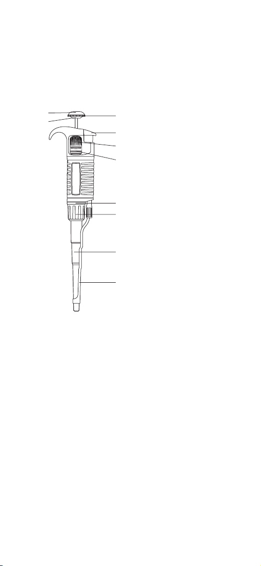
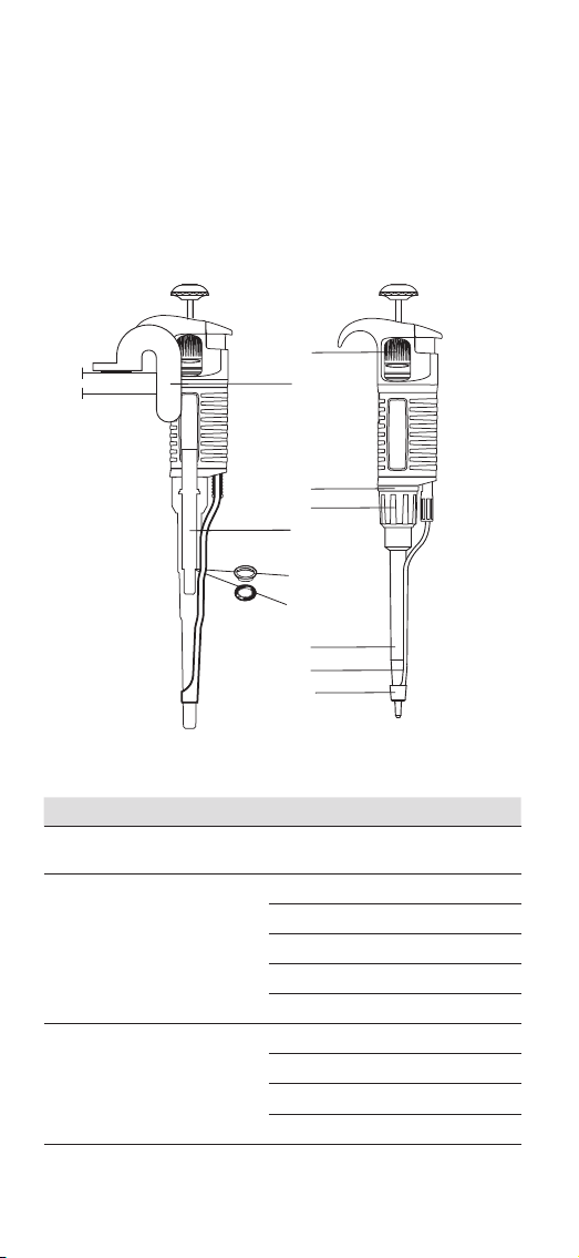
3. Pipette Design
Model Identication
The pipette shaft comes in red, yellow, and blue depending
on the volume range of the pipette. The volume range of
the pipette is also displayed on the pushbutton.
Pipetting pushbutton (A)
Ejector pushbutton (N)
Volume adjustment knob (B1)
Locking ring (B2)
Color identification ring (P)
Shaft (C)
Tip ejector (D)
Shaft nut (F)
A1
A2
A. Pipetting pushbutton: Consists of 2 parts:
thepushbutton (A1) and the knob (A2).
B1. Volume adjustment knob: Used to set thevolume.
B2. Locking ring: Allows the volume setting to be locked by
pushing the ring upwards.
C. Shaft: Manufactured using high quality plastic,
ensuring high chemical and mechanical strength.
D. Tip ejector
F. Shaft nut
N. Ejector pushbutton
P. Color identication ring

Instruction Manual – 3
4. Safety Recommendations
Long-term use of the pipette relies on correct method of use.
Please read and follow the instructions for use carefully.
Symbols used:
Danger, risk of injury.
NOTE Risk of damage to the pipette or errors in pipetting.
NOTE:
• The pipette is designed for the transfer of liquids only
using the tip. Do not aspirate liquids without the tip
attached. The aspirated liquid should not enter the
pipette, asit may cause damage.
• Single-use tips reduce the risk of contamination of
samples.
• Keep the pipette clean, avoiding the use of abrasive or
corrosive cleaning agents (e.g., acetone).
• Keep the pipette upright when there is liquid in the tip.
• Only using the pipette in accordance with the
manufacturer’s instructions ensures the correct pipette
parameters are maintained.
• After replacing the plunger or the shaft, the pipette
should be calibrated.
• In the case of incorrect operation, the device should
be cleaned in accordance with the Instructions for use
ortransferred to a service point.
• Ambient operating temperature is +5°C to 45°C.
• Ambient storage conditions (in the original packaging
during transport and short storage) is -25°C to 55°C.
When working with the pipette:
• Follow general work safety regulations regarding
hazards related to work in the laboratory.
• Take special care when pipetting aggressive substances.
• Use appropriate protective attire (e.g., clothing, goggles,
and gloves).
• Avoid pointing the pipette at yourself or others during use.
• Only use parts and accessories recommended by the
manufacturer.

4 – EPRO® SAILOR™ PIPETTES
5. Specications
The pipette is a high quality instrument which oers
excellent accuracy and precision. The accuracy and
precision (repeatability) of the liquid volume depends on
the quality of pipette tips used. The values for accuracy
and precision shown in the table below were obtained
using manufacturer non-lter pipette tips. Those tips
are recommended for use to ensure compatibility,
accuracy and precision when pipetting. The manufacturer
recommends using EPRO® tips.
Nominal
Volume
(μL)
Volume
(μL)
Accuracy
(%)
Precision
(%)
Non-lter
Tips (μL)
2
Min. 0.1 ±40.0 ≤12.0
10
0.2 ±12.0 ≤6.0
1 ±2.7 ≤1.3
Max. 2 ±1.5 ≤0.7
10
Min. 0.5 ±4.0 ≤2.8
10
1.0 ±2.5 ≤1.8
5.0 ±1.0 ≤0.6
Max. 10.0 ±0.5 ≤0.4
20
Min. 2 ±3.0 ≤1.5
20010 ±1.0 ≤0.5
Max. 20 ±0.8 ≤0.3
200
Min. 20 ±1.2 ≤0.60
200100 ±0.8 ≤0.25
Max. 200 ±0.6 ≤0.20
1,000
Min. 100 ±1.6 ≤0.40
1,000500 ±0.7 ≤0.20
Max. 1,000 ±0.6 ≤0.15
The accuracy and precision were obtained gravimetrically
using manufacturer tips performing at least 10measurements
ofdistilled water at a temperature of 20°C ± 1°C according to
ENISO 8655 standards.
The use of tips from other manufacturers or lter tips may
result in incorrect liquid aspiration and require pipette
recalibration.
The design of the pipette enables the user to recalibrate it
according to the information presented in Section 9.
Instruction Manual – 5
6. Pipette Operation
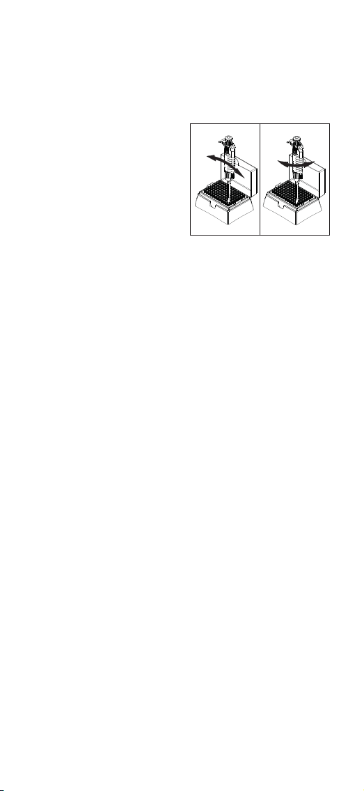
Attaching the Tips
• Attach the correct tip corresponding to the model number
displayed on the pipette pushbutton (Section5).
• Position the pipette
verticallywhen
attachingtips.
• Push the pipette tip
on rmlyusing a slight
twistingmotion to
ensureanairtight seal.
NOTE:
• Do not attach the tips with a rocking movement,
as this may damage the shaft or plunger. Observe this
rule particularly with single channel pipettes of low
volume range.
• Never draw liquids directly into the pipette without
thetip attached.
Adjusting the tip ejector
The tip ejector can be adjusted by the user and can
accommodate most types of tips available on the market.
When using narrow tubes, it may be necessary to remove
the tip ejector.
✓✕

6 – EPRO® SAILOR™ PIPETTES
1. Tip ejector disassembly
• Press the tip ejector pushbutton.
• Turn the metal tip ejector 1/3 turn counter-clockwise.
• Slide the ejector from the plastic arbor.
2. Tip ejector assembly
• Press the tip ejector pushbutton.
• Line the metal tip ejector up with the plastic arbor.
• Turn the metal tip ejector clockwise until it has fully
latched.
3. Tip ejector adjustment
• Remove the tip ejector pushbutton.
• To increase the ejector length turn the plastic bush
counter-clockwise.
• To decrease the ejector length turn the plastic bush
clockwise.
Instruction Manual – 7
If the tip ejector cannot be adjusted
suciently, or if the diameter of the
ejector is insucient to eject the tip, it
may be necessary to attach the ejector
cap “M” to the ejector.
For 2 and 10 μL pipettes place the cap,
supplied with the pipette, on the bottom
of the pipette shaft and slide thecap
upwards to the bottom of the tip ejector.
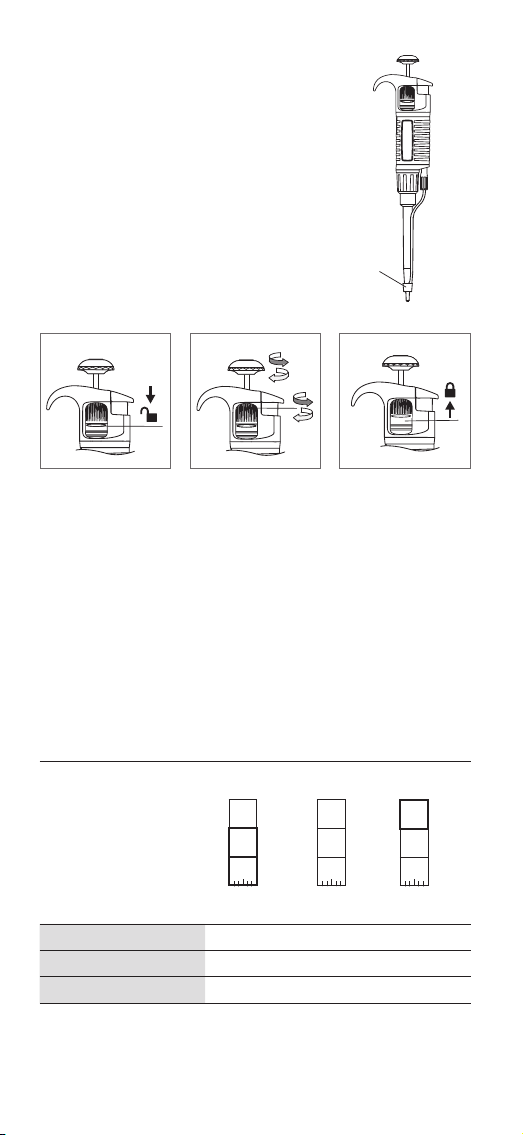
Volume Setting
1. 2. 3.
1. To enable volume selection, set the locking ring to the
lower position.
2. Aspiration volume can be set by either turning the
pipetting pushbutton knob, or the adjustment knob.
The volume setting is displayed as a three digit counter,
which should be read from top to bottom. The smallest
volume increment is printed on the bottom counter drum.
3. After the volume has been set, set the locking ring to the
upper position to avoid inadvertent changing of volume.
Examples of counter indications
The decimal point in the
volume of aspirated liquid
(µL or mL) is indicated by
change in colour of digits.
Black digits represent
integer numbers, and red
digits represent decimal
fractions (pipettes up to
20 μL).
1
2
5
red
red
0
3
5
0
7
5
red
Volume Ranges 0.1-2 µL 20-200 µL 100-1,000 µL
Set Volume 1.25 µL 35 µL 750 µL (0.75 mL)
Increment 0.002 μL 0.2 μL 2.0 μL
M

8 – EPRO® SAILOR™ PIPETTES
For maximum accuracy, the set volume must be approached
from a higher value by decreasing counter readings. Before
reaching the desired value, reduce the speed of turning
the adjustment knob to avoid inadvertently exceeding the
desired value.
7. Operating Instructions
Observing the following recommendations will ensure
maximum possible accuracy and precision of liquid sampling.
• During operation, the volume setting should be locked,
with black adjustment knob in the lower position.
• Ensure smooth and slow operation of the pipette.
• Immersion of the tip into the sample liquid should
be kept to a minimum depth, which should remain
constant during aspiration. The recommended
immersion depths are given in the table below:
Model Volume Range (µL) Immersion Depth (mm)
0.1-1 ≤1
1-100 2-3
101-1,000 2-4
• The pipette should be held in a vertical position.
• The pipette tip should be changed whenever the volume
setting is altered, and when a dierent liquid is to be
aspirated.
• The pipette tip should be changed if a droplet remains
on the end ofthe tip from the previous pipetting
operation.
• Each new pipette tip should be pre-rinsed with the
liquid to be pipetted.
• Liquid should never enter the pipette shaft. To prevent this:
– Press and release the pushbutton slowly and
smoothly.
– Never turn the pipette upside down.
– Never lay the pipette on its side when there is liquid in
the tip.
• Never force the volume setting beyond
therecommended limits.

Instruction Manual – 9
• When pipetting liquids with a dierent temperature
from the ambient temperature, it is recommended to
pre-rinse the tip several times prior to use.
• Do not pipette liquids with temperatures above 70°C.
NOTE: When pipetting acids or corrosive solutions which
emit vapors, it is recommended to disassemble the shaft
and rinse the plunger and O-ring with distilled water after
nishing the pipetting operation.
8. Aspiration and Dispensing Instructions
1. 2. 3. 5.4. 6.
Aspirating Liquid
1. Press the pushbutton to the rst stop point.
Holdingthe pipette vertically, immerse the pipette tip
into the sample liquid to the recommended depth (for
recommended values see Section 7). Ifthepipette tip
is not immersed to the recommended depth or if the
pipetting pushbutton is rapidly released, air may enter
the pipette tip.
2. Release the pipetting pushbutton slowly and smoothly
to aspirate the sample. Wait one second and then
withdraw the pipette tip from the liquid.
CAUTION: Do not touch the used tip.

10 – EPRO® SAILOR™ PIPETTES
Dispensing Liquid
3. Place the end of the pipette tip against the inside wall of
the vessel at an angle of 10° to 40°. Press the pushbutton
smoothly to the rst stop. Wait one second.
4. Press the pushbutton to the second stop to expel
any remaining liquid. While keeping the pushbutton
depressed, remove the pipette from the vessel by
drawing the pipette tip against the inside surface of
thevessel.
5. Release the pushbutton to its starting position.
6. Eject the pipette tip by pressing the tip ejector
pushbutton.
Remember to change the pipette tip whenever a
dierent type of liquid is to be sampled.
Aspirating High-density Liquids
When pipetting liquids of higher viscosity or lower surface
tension than water (e.g., sera or organic solvents), a lm
of liquid may be formed on the inside of the pipette tip
which may produce erroneous results. As the lm remains
relatively constant in successive pipetting operations with
the same tip, this error can be eliminated by pre-rinsing
the tip and allowing a lm to form before transferring the
rst sample. This is achieved by aspirating asample and
dispensing it back into the same vessel. Allowing a lm
to form prior to sampling ensures optimal accuracy and
repeatability.
This pre-rinsing operation should be repeated when
thevolume to be aspirated is changed or when a new
pipette tip is used.
NOTE: Normally the degree of error resulting from viscous
liquids is negligible if pipetting is performed slowly and
carefully, however can be minimized further by holding
the pipette tip in position for at least 2 seconds after
aspiration to allow the liquid time to react to the change
in pressure before it is dispensed.
If the above method does not result in accurate values,
recalibrate the pipette in accordance with Section 9.
It is recommended to record recalibration and correction
values, in order to facilitate reverse calibration to astandard
liquid.

Instruction Manual – 11
9. Checking Pipetting Accuracy Parameters
and Pipette Recalibration
The EPRO® Sailor™ pipettes have been factory-calibrated
using gravimetric methods with manufacturer pipette tips
and distilled water, in accordance with ISO 8655 guidelines
for the maximum (nominal) liquid volume drawn by the
pipette and for 10% of the maximum or minimum liquid
volume according to the values given (Section 5).
The EPRO® Sailor™ pipettes are designed to enable
recalibration and adaptation to dierent pipetting
techniques and liquid properties (e.g., temperature,
density, and viscosity).
Periodic checks of the operation of the pipette are
recommended at least once per year. Frequency of checks
should be increased depending on workload, sterilization
or autoclave processes, and frequency of replacement of
component parts.
If during pipette operation the accuracy error (the
dierence between the real aspirated volume and the
preset volume) exceeds the permissible value given
inthetable in Section 5, pipette recalibration should be
carried out.
Recalibration of the pipette involves volume adjustment
based on the value obtained by weighing. Recalibration of
the pipette is performed only for one liquid volume drawn
by the pipette.
The recommended volume for recalibration is 10% of the
maximum (nominal) value or minimum volume depending
on which of these values is greater. See table onpage 13 for
more details.

12 – EPRO® SAILOR™ PIPETTES
Parameters for Checking the Pipetting Accuracy
The pipetting accuracy is inuenced by factors such as:
tips used, characteristics of the pipetted liquid (density,
viscosity), and operating conditions (ambient temperature,
pressure).
To determine the accuracy error of the pipette, the following
conditions should be met:
• Ambient temperature and temperature of the pipette,
pipette tips, and liquid should be within the range of
20°C to 25°C and stabilized during weighing within
±0.5°C.
• Measurements should be conducted using distilled water.
• Balance sensitivity should be suitable for the volume “V”
to be measured.
Volume Checked (V, μL) Balance Sensitivity (mg)
0.1≤V≤10 0.001
10≤V≤100 0.01
100≤V≤1,000 0.1
• When calculating the liquid volume aspirated by
thepipette, the conversion factor (Z) [μL/mg] for
distilled water or a liquid with comparable density
should be taken into account. Sample values of
conversion factors are given in the following table.
Temperature
(°C)
Pressure (kPa)
95.0 101.3 105.0
20 1.0028 1.0029 1.0029
21 1.0030 1.0031 1.0031
22 1.0032 1.0033 1.0033
23 1.0034 1.0035 1.0036
24 1.0037 1.0038 1.0038
25 1.0039 1.0040 1.0040
See ISO 8655 for the full table of conversion factors (Z).
NOTE: Pipetting should be performed in accordance with
guidance described in Sections 7 and 8.
Checking the Pipetting Accuracy Parameters
• Set the preset volume depending on the pipette volume
according to the following table.

Instruction Manual – 13
Nominal
volume
(µL)
Preset
volume
(μL)
Permissible
values (μL)
Volume Change ΔV (μL) for a
Turn of a Calibration Key by
1 Turn 1 Increment
20.2 0.176 - 0.224 0.06 0.0025
10 1 0.975 - 1.025 0.33 0.0137
20 2 1.94 - 2.06 0.63 0.0262
200 20 19.76 - 20.24 6.30 0.262
1,000 100 98.4 - 101.6 25.00 1.04
• Perform 10 aspirations, and calculate the average value
in [mg].
• Calculate the volume in [μL] by multiplying the value
in[mg] by the conversion factor Z [μL/mg].
If the average aspirated volume exceeds the permissible
values of the range, the pipette should be recalibrated.
Pipette Recalibration
K
1. Remove the pipetting pushbutton.
CAUTION: The pipetting pushbutton consists of 2 parts:
the knob and the pushbutton. After removal of the
pushbutton, both parts are separated.
2. Holding the volume setting knob to prevent rotation,
insert the calibration key into the calibration screw.
3. Turn the key clockwise to reduce the aspirated volume,
or counter-clockwise to increase the aspirated volume.
Use the values given in the above table to precisely
adjust the volume.
K
1. K
K
K
2. 3. 4.

14 – EPRO® SAILOR™ PIPETTES
4. Remove the key and replace the pipetting pushbutton by
rst replacing the knob, then the pushbutton.
Determine the average aspirated volume. The average
volume should be within the permissible range given in
the table. If the volume exceeds the values stated, the
recalibration procedure should be repeated.
When pipetting liquids with physical properties
considerably dierent from those of water, follow
theguidance given in Section 5.
More information on the calibration procedure can be
found at www.eproscience.com and
https://shop.eproscience.com.
10. Pipette Maintenance
Depending on the applications and intensity of use, the
EPRO® Sailor™ pipette requires periodic maintenance.
Thecomponents exposed to corrosive vapors, such as
shaftelements, should be regularly checked and cleaned.
Do not use sharp tools for pipette maintenance. Itmay
cause damage to the device and aect the user’s safety.
Cleaning
External surfaces of the pipette such as the pushbutton,
ejector pushbutton, handgrip, shaft nut, and adjustment
knob may be cleaned using a cloth dampened in isopropyl
alcohol. The remaining parts removed from the pipette
during pipette disassembly may be washed with distilled
water or isopropyl alcohol.
NOTE: Before using cleaning agents other than those
recommended by the manufacturer, check the compatibility
charts and consider chemical resistance of the following
plastics which form components of the pipette: PP, PC,
POM, PA, PPS, PVDF.
Sterilization
Sterilization using an autoclave
The EPRO® Sailor™ pipettes can be sterilized in an
autoclave at 121°C for 20 minutes. Sterilization under
other conditions may cause damage to the pipette. It is
recommended to:
• Unscrew the shaft nut slightly. Prior to autoclaving, and
once autoclaving is nished, the nut should be screwed
tight again.

Instruction Manual – 15
• Set the locking ring to the lower (unlocked) position
prior tosterilization.
• Sterilize the pipettes using an autoclave with an initial
vacuum and drying cycle.
• After sterilization, the pipette should be dried and
cooled to room temperature.
Precision and accuracy should not alter if the pipetting
processes including autoclaving are carried out as
described in this manual. If a change in accuracy occurs,
itis recommended to:
• Check the calibration of the pipette after the rst,
third, and fth autoclaving cycles and then after every
10autoclaving cycles.
Ultra Violet (UV) Sterilization
The EPRO® Sailor™ pipettes are UV resistant. The distance
from the radiation source to the exposed element of the
pipette should be at least 50 cm. Prolonged or intense UV
exposure can cause discoloration of pipette parts but does
not aect its performance.
11. Troubleshooting
If a problem is encountered during pipette operation, use
the following table to identify and eliminate the fault
following the instructions provided. Replacement of parts
should be required only occasionally and should not be
required with normal pipette use.
Problem Cause Solution
Droplets of
liquid remain
in the pipette
tip.
The pipette tip is emptied
too fast.
Decrease the speed
of pressing the pipette
pushbutton.
The pipette tip wettability
has increased due to
extensive use.
Replace the tip with
a new one.
Droplets
of air appear
in the liquid
aspirated
into the
pipette tip.
The pipette tip immersion
depth is too shallow.
Immerse the tip
to the recommended
depth according to the
instructions.
The pipette tip is
incorrectly pressed onto
the pipette shaft.
Press the pipette
tip rmly onto the
pipette.
The tip is damaged or
worn out due to extensive
use.
Replace the tip with
a new one.

16 – EPRO® SAILOR™ PIPETTES
Problem Cause Solution
The pipette
incorrectly
aspirates
the liquid
or the liquid
drops out
from the tip.
The pipette tip is
incorrectly pressed onto
the pipette shaft.
Press the pipette
tip rmly onto the
pipette.
The shaft surface is
damaged or contaminated
at the sealing site.
Clean the shaft or
replace it with a new
one.
The plunger or the
O-ring is damaged due
toprolonged aspiration
ofcorrosive liquids.
Disassemble the
shaft set; wash the
shaft, the plunger and
the seal (Section 10:
Cleaning). Replace the
elements with new
ones if necessary.
Apply a small amount
of lubricant onto
the plunger and
reassemble the set
inthe correct order.
The inside of the pipette is
contaminated.
The sealing elements are
not suciently lubricated.
Uneven
work of the
pipetting set,
the pipetting
pushbutton
gets blocked.
The inside of the pipette
is contaminated due to
aspiration of corrosive
substances.
Unscrew the shaft
set, wash the parts.
Replace the elements
with new ones if
necessary. Apply
a small amount
of lubricant on
the plunger and
reassemble the set
inthe correct order.
The inside of the pipette is
contaminated due to the
liquid entering the pipette.
The sealing elements are
not suciently lubricated,
e.g. after repeated
autoclaving procedures.
Incorrect
aspiration.
Liquid with properties
other than water (density,
viscosity).
Calibrate the pipette
using the liquid which
is to be pipetted.
Tips with a lter with
increased ow resistance.
Calibrate the pipette
using the tips which
are to be used for
pipetting.
If the problem persists after carrying out the above steps,
contact our regional representative.
Before returning the pipette, please ensure the pipette
is completely free of any chemical, radioactive, or
microbiological contamination which could pose athreat
during transport and repair.
Instruction Manual – 17
12. Spare Parts
Contact our Customer Service to inquire about the
availability of spare parts. Pipette model and name of the
part required should be specied. The most common parts
are depicted below.
NOTE: The replacement of the plunger requires conducting
the calibration procedure according to Section 9.
I
J*
GG
B
F
P
C
D
M
S
Item Description Model Cat. No. Qty/Pk
BVolume adjustment
knob set
All ESP20221 1
C, I,
J*
Shaft with O-ring and
seal
2 ESP20222 1
10 ESP20223 1
20 ESP20224 1
200 ESP20225 1
1,000 ESP20226 1
D Tip ejector 2, 10 ESP20211 1
20 ESP20212 1
200 ESP20213 1
1,000 ESP20214 1
*Seal (J) used only in 2 µL model

18 – EPRO® SAILOR™ PIPETTES
Item Description Model Cat. No. Qty/Pk
F Shaft nut All ESP20210 1
G Plunger assembly 2 ESP20215 1
10 ESP20216 1
20 ESP20217 1
200 ESP20218 1
1,000 ESP20219 1
I, J* O-ring (and seal) 2 ESP20227 10
10 ESP20228 10
20 ESP20229 10
200 ESP20220 10
1,000 ESP20230 10
K Calibration key All ESP20231 1
M Tip ejector cap 2, 10 ESP20232 3
PColor indentication
rings
All ESP20233 6
S Wall mount All ESP20234 1
*Seal (J) used only in 2 µL model
Table of contents
Other epro Industrial Equipment manuals

Popular Industrial Equipment manuals by other brands

Hydrotech
Hydrotech HSF2200 Series Operation & maintenance manual

Bungard
Bungard EXP3040LED instructions

Eaton
Eaton Airflex CB Installation & operation

Dustcontrol
Dustcontrol TPR 50 Original instructions

DUSTLESS BLASTING
DUSTLESS BLASTING DB150 user manual

KINSHOFER
KINSHOFER KM 506 HD operating instructions


TAAG
TAAG TIN KNOCKER MWETK-RFBL20 INSTRUCTIONS & PARTS DIAGRAM

Bosch
Bosch Rexroth BS 2/C Series Assembly instructions

Altronic
Altronic GTI Bi-Fuel Installation & operating manual

ABB
ABB Orion1 Base Original instructions

Emerson
Emerson Fisher ENVIRO-SEAL instruction manual

Eaton
Eaton PowerPass 9PXTFMR5 user guide