epro Combi Machine User manual

Version 1.0
April 2021
Combi Machine
User Manual

Contents
Product description:............................................................................................................ 4
Intended use:............................................................................................................... 4
General structure:........................................................................................................ 5
Functional principle: .................................................................................................... 6
General safety instructions:................................................................................................ 7
General instructions for device configuration:................................................................... 7
Electrode management system with compliance balancer: ....................................... 8
Selection of the milling tool:........................................................................................ 8
Installation instructions: ..................................................................................................... 9
Process flow welding-milling exchanging: ........................................................................ 10
General process flow:................................................................................................ 10
Milling sub-process:................................................................................................... 12
Exchange or replacement sub-process:..................................................................... 13
Programming: ................................................................................................................... 14
Alignment: ................................................................................................................. 14
Milling programming:................................................................................................ 15
Programming electrode extractor:............................................................................ 16
Orientation and grease access: ................................................................................. 17
Programming electrode replacement: ...................................................................... 18
Exchange and changing of the electrode cartridges: ................................................ 19
Testing electrodes and adapters: .............................................................................. 19
Optimization of milling process: ....................................................................................... 20
Operating parameters: .............................................................................................. 20
Milling format:........................................................................................................... 21

Chip formation and service life of the electrode: ..................................................... 22
Gun pressures that can impact performance:........................................................... 23
Troubleshooting:............................................................................................................... 23
Maintenance:.................................................................................................................... 32
Inspection of magazine cartridges (2-3 days):........................................................... 32
Inspection of changing canisters (monthly): ............................................................. 32
Care of the milling tools: ........................................................................................... 32
Overview of maintenance intervals: ......................................................................... 33
Contact.............................................................................................................................. 34

Product description:
Intended use:
The Combi machine is designed for spot welding devices and robotic applications. It is an
automated process compliant with ISO 5821 (CuCrZr) where electrode caps on a resistance
spot welding gun are reshaped by a milling tool or removed and replaced through an
automatic electrode exchange process.
Important Safety Notes:
Objects in the milling tool of the machine must not be handled manually. Electrode
caps milling devices for hand-welding guns must be used according to the service
instructions.
No work pieces or materials other than spot welding electrodes according to ISO 5821
(CuCrZr, CuZr, CuCr) may be used.
Personal protective equipment to be used as required.
For correct use of the machine, please review the entire operating manual and follow the
safety instructions.
We do not take responsibility for any injury or damage which had been
caused by improper use, inadequate installation or maintenance.
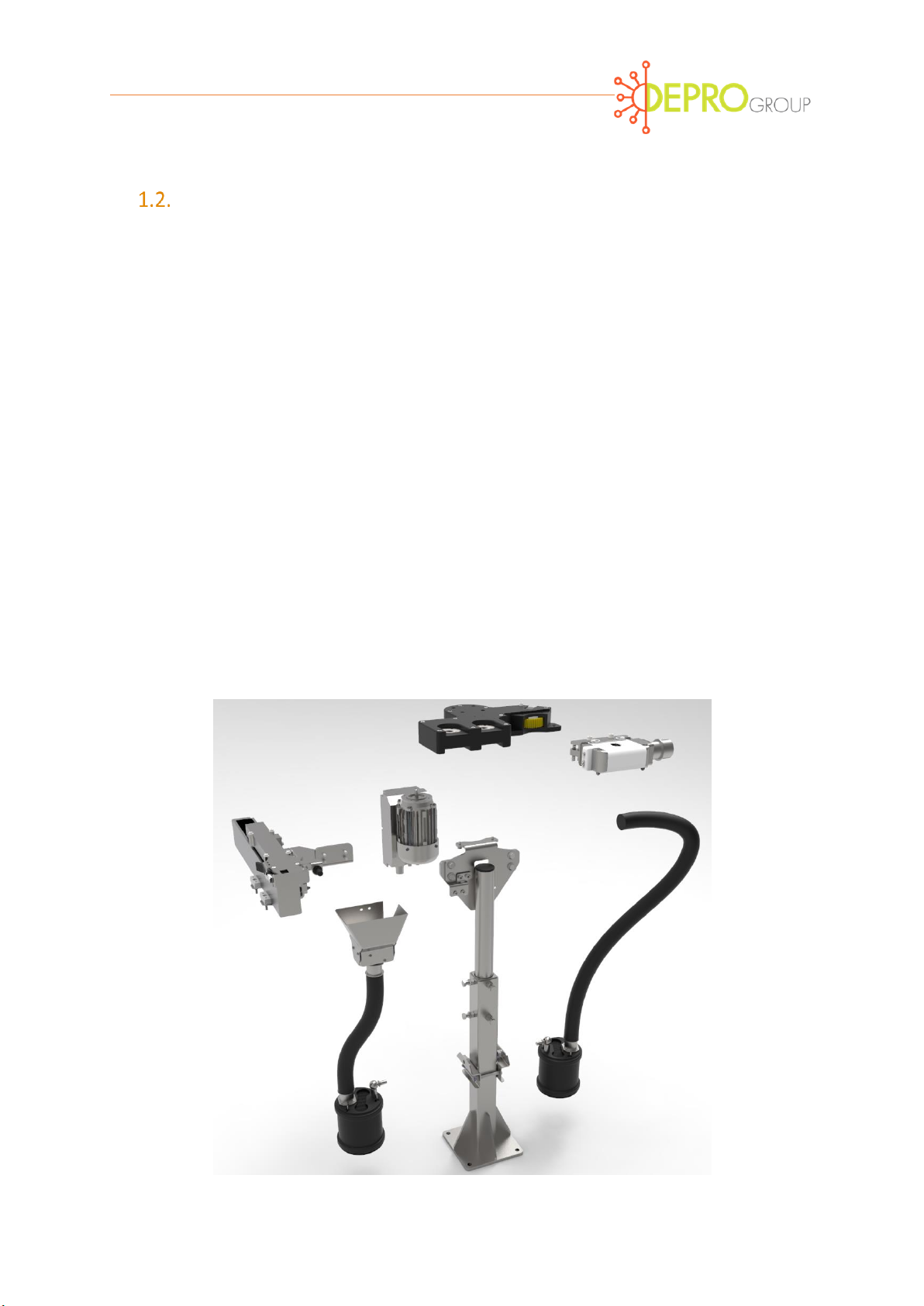
General structure:
The Combi machine (figure 1) has a modular design that is individually configured for a wide
variety of reshaping and replacement electrode applications. The machine can be oriented
vertically or horizontally, consist of a Cap Dresser assembly, Gearbox, Lenze smart motor
m300, Magazine, evacuation system that consists of a tube and a cap collecting canister, Stand
(supporting system), adapting plate allowing to switch between the vertical and horizontal
configuration.
The Combi machine is made up of several subcomponents as indicated by Figure 1 . Cleaning
of the milling tools from excess electrode material takes place during and after milling.
Removed electrodes are collected in separate integrated collection container.
Optional: Used electrodes and milling debris can be collected in separate waste container
depending on container configuration while electrical box configurations and stand
configurations can vary depending on need and requirement.
Figure 1 Combi Machine
Cap
Dresser
Assembl
Lenze Smart
Motor m300
Gearbox
Evacuation
Tube
Cap Collecting
Canister
Stand
Magazine
Adapting
plate

Functional principle:
In spot welding, the heat required to fuse the weldments is determined by the current, the
current flow time and the pressure of the closing force that form the weld nugget. Figure 2
shows the process and the formation of the weld nugget. Due to the constant interaction of
heat and pressure, the working surface geometry of the electrode cap changes and the work
surface increases in addition to the formation of a burr at the periphery. As the working area
increases in size the current per mm2 of work surface decreases, resulting in the deterioration
of the weld quality.
Welding quality degradation can also be associated with the properties of copper and zinc.
For example, in the automotive industry for reasons of corrosion protection, galvanized steel
sheets is being used more often. Through the welding process there is a formation of
contaminant material (buildup of zinc layers) on the electrode work surfaces resulting in an
increase of resistance to the work area, resulting in a loss of energy at the electrode working
surface, which is needed for heating the weld metal. This result in a lack of repetitiveness of
the expected welding result.
In order to achieve a reproducible welding result, the specific current intensity can be adjusted
proportionally to the work area magnification and the loss resistance via a stepper function.
Electrode management systems are used to repair and replace worn tips of welding electrodes
(ISO 5821). The welding robot brings the electrode caps or tips to the closed position in the
rotating cutter tool where both electrodes are brought to an acceptable shape at the same
time, free of impurities and deformed material.
Figure 2 Spot welding time cycle

General safety instructions:
Care on part of the owner / operator:
The machine may only be operated by persons who are trained, instructed and authorized to
do so. These persons must be familiar with the operating manual and act accordingly when
accessing the machinery.
Basic safety measures to be addressed include:
The welding machine should not operate on its own.
Access to the Cap Dresser and/or the protected area should remain clear but also
secure.
Robots and other plant components should be suitably secured.
Be aware of all safety protocols related to robots and electrical codes.
When changing tools and working on a machine, the power has to be switched off.
Work on the terminal box must be carried out by qualified personnel (electricians).
Operating without a protective cover removed is not recommended and protective
eyewear is recommended.
Gloves are recommended when working with chips or debris from the machinery.
Be aware of pinch points on the unit.
Stay away from electric drive when in operation or under power.
General instructions for device configuration:
Devices are modular so they can be quickly and easily adapted to the various installation
configurations.
Before commissioning the device, it should be checked by a simulation or locally in the welding
system to identify that it has been configured correctly. The geometry of the welding guns
must permit for a collision-free entry and retraction of the electrode caps into the milling
cutter for satisfactory milling result.
Also, the use of tools that are not suitable for the existing electrode pairing, can lead to serious
damage of the milling tool or electrode caps.
Electrode management system with compliance balancer:
The optimum use of the electrode management system is a vertical mounting configuration
although options are available for mounting in different configurations.
The task of the compliance balancer (Figure 3) is to compensate
for slight differences in the shortening of the welding caps. In a
new electrode configuration with two new welding caps, the
compliance balancer should remain in the normal position.
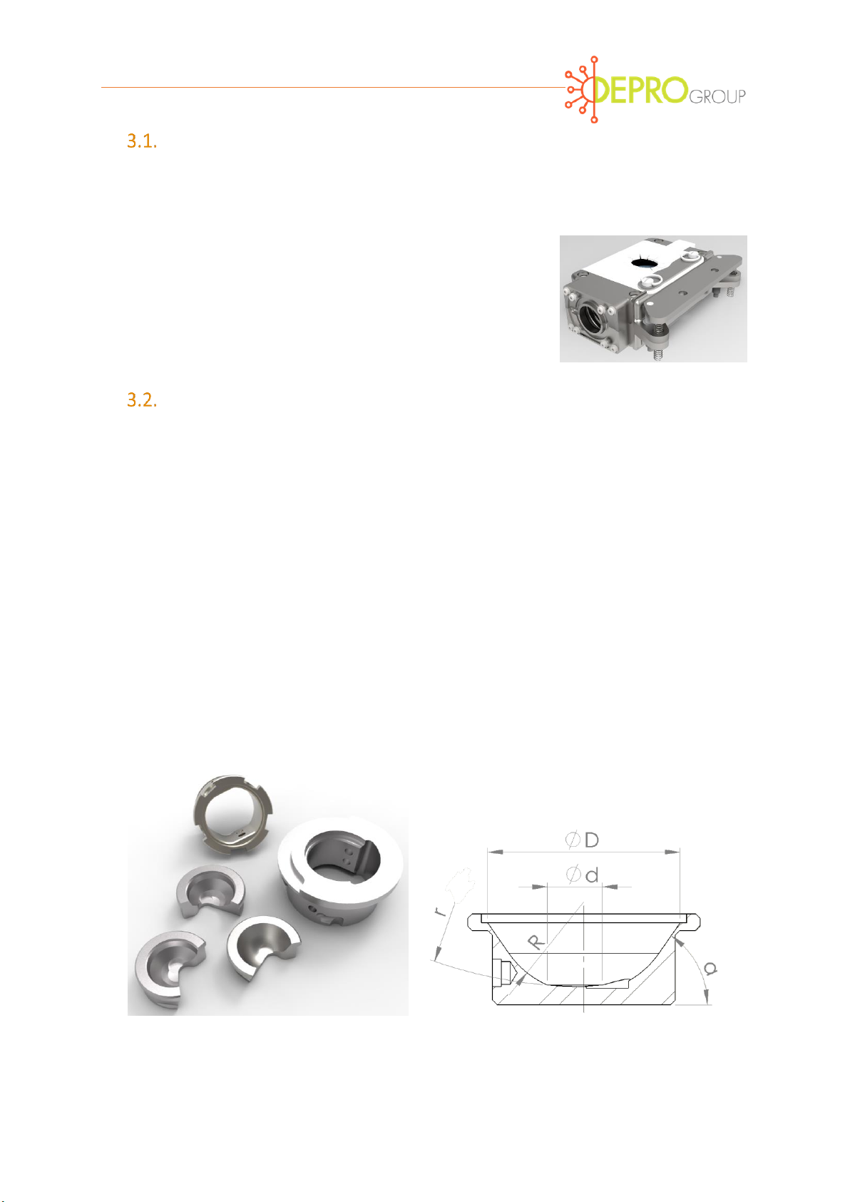
Selection of the milling tool:
Selecting the correct milling tool is based on the geometry of the upper and lower electrode
caps. The milling tool consist of a holder and cutter or blade that is held in place with a set
screw (Figure 4). Some tools come with Blue rings that must be snapped in place to ensure a
proper fit. Other holders come without a ring and equally provide enough protection so that
debris does not enter the housing.
Before the first use of the electrode milling tool, the selection of the tool must be checked on
the basis of basic characteristics which include total electrode diameter (D), effective surface
diameter (d), radius of active surface (r), as well as electrodes flanks (R) or flank angle ()
(Figure 5). Provide these specifications so that the correct product can be ordered to your
customized needs.
Figure 4 Cutters and holders Figure Figure 5 Features of the milling tool
Figure 3 Balancer

Installation instructions:
Precise installation is required for the stand or pivot arm so that a robot can mill or
change an electrode cap with precision.
The milling tool can be reached directly from the welding robot. Long distances can
unnecessarily extend the cycle time of the entire system. Review gun dimensions to
ensure accessibility of the electrode caps to the Milling tool.
Position the tool as indicated in Figure 9 so that the lugs or wings from the blade holder
fit into the machine gear and turn 90 degrees. Test that the tool is in place by pushing
on the backside of the holder. The holder should be secured and should not be
dislodged if the lugs are in place.
If the holder of the milling tool is equipped with the blue ring, ensure the ring is
snapped in place to the holder. Alternate holders are available without the blue ring
(Figure 10).
Ensure there are no collisions with welding parts, robots or other moving elements in
the welding area. As a check, the entire workflow should be simulated.
All machine connections including cables, hoses and pipelines, should be laid so that
they do not cause a tripping hazard. Laying cables and hoses with prescribed bending
radiuses are to be observed to avoid leaks and electrical contact.
Ensure all fasteners are secured.
Ensure accessibility for maintenance and repair work is to be observed.
Additional supply and electrical connections:
Filtered compressed air for the chip removal at 6-8 bar.
Supply for the three-phase drive depending on the device (380-575 VAC / 50-60 Hz).
Current protection 8 amps.
Lines with 24 VDC for motor switches, valves, as well as rotation speed and limit
position switches.
Optional: Remote bus system e.g. Interbus-S.

Check the function of each supply line independently via the manual overrides or the system
PLC. Ensure FIGURE 9 HOLDER AND BLADE INSTALLATION FIGURE 10 STANDARD HOLDER AND
BLADE THAT MAKE UP THE MILLING TOOL8
An air steam is present within the milling unit on both sides, diagonally above the
milling tool as well as at the end of the exhaust pipe.
The electric drive has the correct direction of rotation (clockwise from the top of the
gearbox).
The machine is not designed for continuous operation and as a result it is
recommended that subroutine be developed in the PLC run-time limiting run time to
a maximum 30 seconds.
In the system PLC, the rotation signal exists while in operation. One version presents a LED
with a fast pulsing signal. An optional version with integrated speed evaluation (3 LED), has a
continuous signal delivered with the correct milling speed.
Process flow welding-milling exchanging:
General process flow:
The process Flow consists of several steps, each of which is set up and optimized for the
number of spot welds before each milling process which depends wear caused by the welding
task. In general, electrodes are to be reshaped after 50-200 weld spots based on optimum
running conditions. Reshaping of electrode pairs may be repeated approximately 20-50 times
before electrodes are replaced.
The general process flow is shown in Figure 6 For a better indication of cutter or blade life it is
recommended that milling be performed before replacing electrodes to in order to measure
the difference in weld face size can electrode quality. The process chain should be followed
for program routine of the PLC device and the robot controller.
Make sure there is no welding current flow during the
milling and electrode replacement cycles. It may damage
the device or components!

Figure 6 General process flow

Milling sub-process:
The sub-process of MILLING (Figure 5.2.1) contains output signals (e. g. output MILLING) and
status feedback (e. g. input MONITORING ROTATION). Make sure that complete signal
exchange is operating correctly before determining the spatial coordinates on the welding
robot in accordance with the following sections. This includes the ability to limit the duration
of milling with closed welding guns using several rotation pulses.
Figure 7 Sub-process milling

Exchange or replacement sub-process:
The sub-process EXCHANGING (Figure 5.3.1) has the output signals (e.g. output EXCHANGING)
and status feedback (for example, input LEVEL OF CAP CARTRIDGE) as identified below.
Figure 8 Sub-Process exchange
Programming:
Figure 9 Magazine alignment
Alignment:
The alignment of the machine is linearly coordinated to robot movement (Figure 9).
Movements are traced in a path as described by the process flow from Figure 7 and 8 which
identify the following linear steps:
1. Check for Gun Electrode A presence (1 - cap detector)
2. Gun Electrode A extraction (2 - extractor)
3. Sensing electrode is absent (1 - cap detector)
4. Replace Gun Electrode A (3 - magazine cartridge 1)
5. Sensing Gun Electrode A is present (1 –cap detector)
6. Check Gun Electrode B presence (1 –cap detector)
7. Gun Electrode B extraction (2 - extractor)
8. Sensing Gun Electrode B is absent (1 –cap detector)
9. Replace Gun Electrode B (4 –Magazine Cartridge 2)
10. Sensing Gun Electrode B is present (1 –cap detector)
11. Close gun to Seat electrodes A and B
12. Milling of Electrodes, A and B (5 Milling Tool)
Magazine
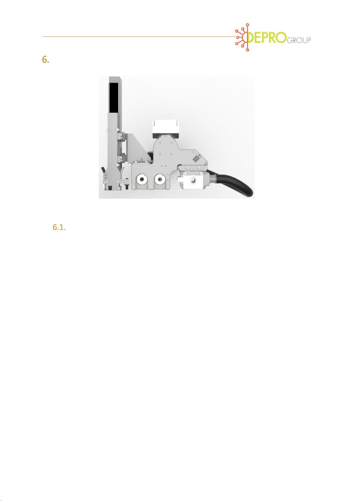
Milling programming:
Once the milling tool is installed in the machine, the robot welding gun and the milling process
are as follows:
The welding electrodes are adjusted linearly to each other and to milling device as in
the welding position (figure 10). When using a C-guns at least one electrode should be
90 degrees to the electrode cutter.
The closing force for milling with Quattro blade tools is 1.5 kN (337.2 lbf) and single
cutting tools is 1 kN (224.8 lbf) (basic setting). Based on this value, the milling result
(material removal) can be optimized later.
The milling time is approx. 2 seconds. This value also can be changed later when
optimizing.
The milling tool should rotate before closing and after opening the welding gun. A lead
time of two seconds before and five seconds afterwards is recommended. During the
post milling process, chips are removed by blow-off and transported into the collection
container. Depending on the extent of the milled contaminants, the post milling
process can be increased up to ten seconds to accommodate additional blow-off.
During the milling operation the welding current must be disengaged as it can damage
the tool.
Figure 10 Position of the electrodes to the milling tool

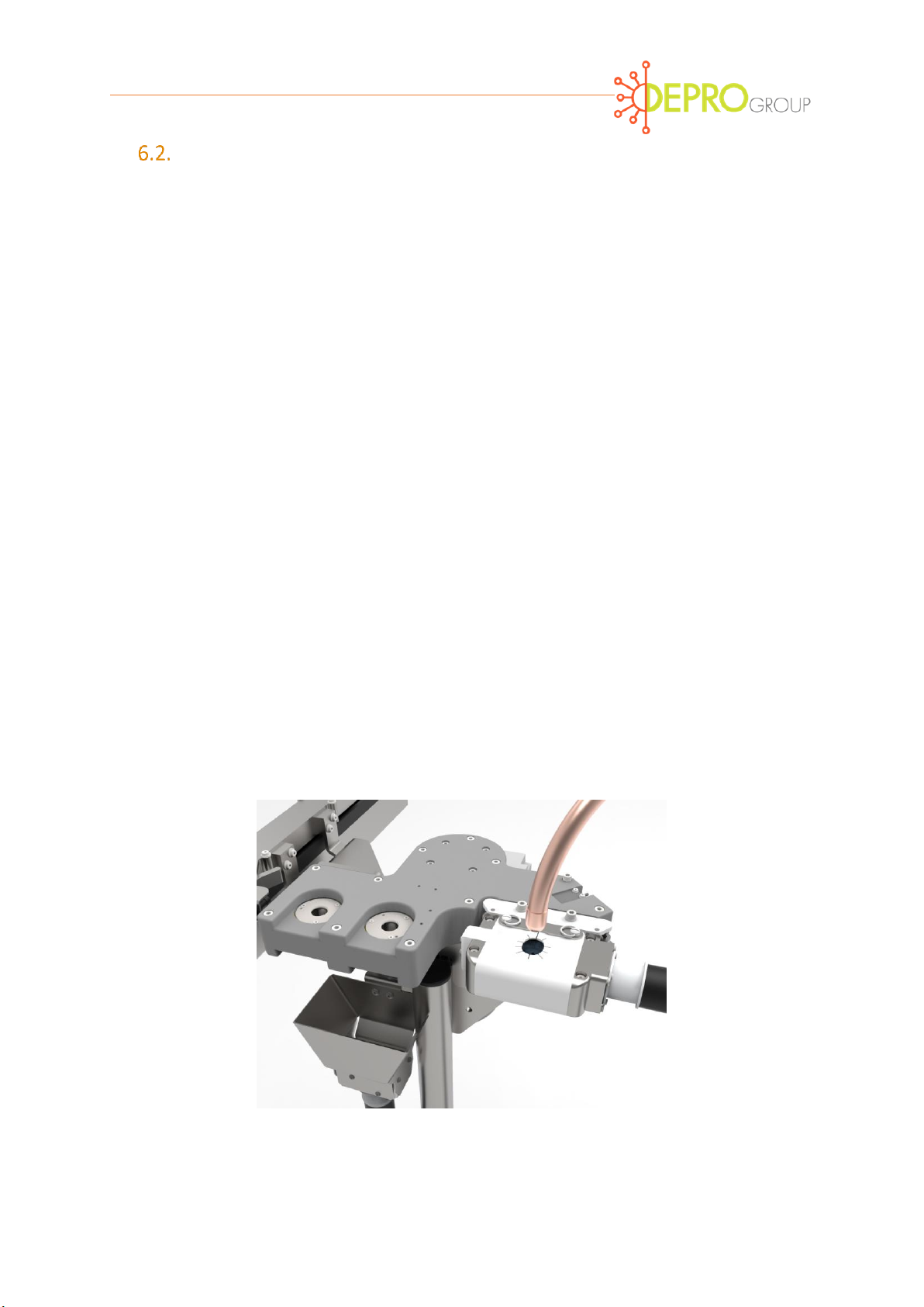
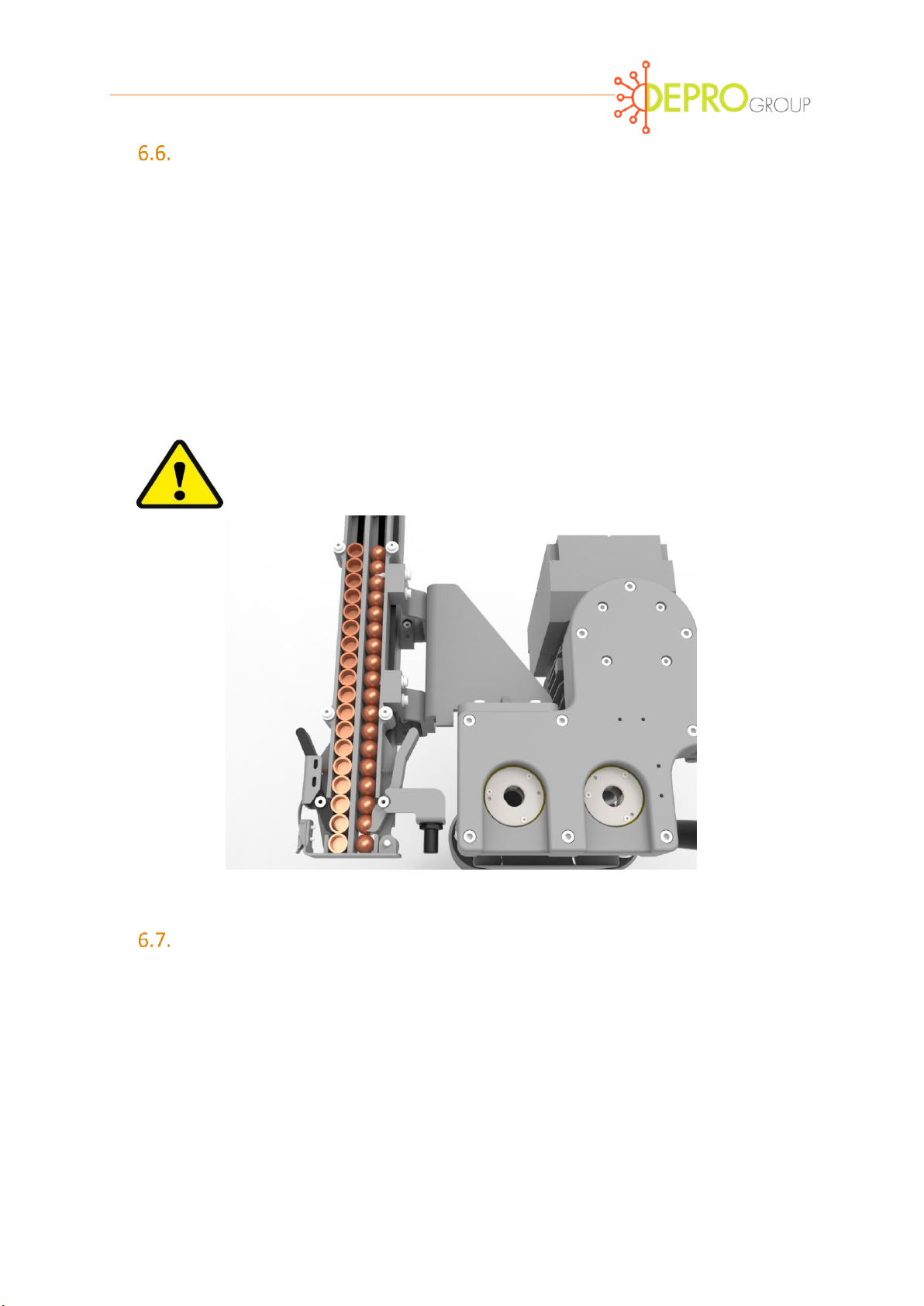
Programming electrode extractor:
The removal of the electrodes is to be programmed as follows:
The electrode to be changed should be positioned to approach the axis of rotation of
the extractor tool and at the same time at right angles to the milling unit (Figure 11).
Welding guns with angled electrode holders must be balanced for a clean and direct
approach to the tool. Caution: incorrect position of the electrodes in the extracting
tool can cause increased wear and tear or even damage to machine and to electrode
holder.
Figure 11 Position of the removal tool
The electrodes are inserted all the way to the upper edge but the removing tool is not
in contact with electrode holder.
The welding guns always remain sufficiently open when changing.
The time to loosen the electrode in the jaws of the extractor is less than one second.
A longer stay in the extraction tool wears the electrode
As the electrode approaches the extractor, the extractor is to run in the opposite
direction of extraction for a minimal number of revolutions to allow entry of the
electrode cap.
Milling
Electrode removal

When engaged, the extractor should remove the electrode cap in a forward motion in
minimal revolutions.
The removed electrode cap will remain in the removal tool and will be pushed out with
the release of the next electrode. As a result, the jaws remain spread and allow easier
retraction of the next electrode to be removed.
Ensure the welding gun is sufficiently opened before leaving the extraction.
Remove one electrode cap at a time.
Orientation and grease access:
Extraction of electrode caps in an electrode management system that is horizontally
mounted, follows the same principals as defined earlier but in order to have the
electrode caps fall into the waste container, the approach of the weld gun must always
be in one direction, from above (Figure 12).
The gun should be turned 180 degrees in order to remove the electrode from the
opposite arm to again have the electrode fall from the extractor into the waste
container.
In the vertical orientation there is a grease access hole below the extractor unit that
would typically never require greasing. In the vertical orientation the hole should be
plugged to avoid water access contamination. In the horizontal orientation the plug
must be removed, and the hole should point downwards for drainage.
Figure 12 Electrode extraction in horizontal configuration
If both electrodes are released simultaneously, the cooling
water escapes from the welding guns unless there is an
active water drawback system.

Programming electrode replacement:
The electrode magazine supplies new electrodes to the robot in an integrated program as
follows:
Each cartridge on the magazine holds new electrode caps and is equipped with an
inductive sensor to identify the presence or absence of a cap or empty magazine that
needs to be refilled (Figure 13).
Figure 13 Position of inductive sensors
Ensure the electrode approach is perpendicular to the electrode cartridge (Figure 14).
Welding guns with inclined electrode holders may need to compensate on the
approach to the new electrode. Attention: incorrect position of electrodes in the
extraction tool may lead to an increase wear or even damage of the machine and
electrode holder or adapter.
The welding gun closing force should not exceed 100 kg when pressing on the new
electrode cap.
Ensure the welding gun is sufficiently opened before leaving the cartridge with the new
electrode cap and it is pulled perpendicular to the cartridge. Diagonal removal of
electrodes can wear out or even damage electrode cartridge.
Figure 14 Gun position to approach the new electrode
Exchange and changing of the electrode cartridges:
When electrodes are consumed and the caps are empty a signal is transmitted with two
inductive sensors located at each cap. To add new electrodes to the caps the entire magazine
can be removed by depressing and removing the 2 ball lock pins (Figure 15). Ensure the lock
pins are in place by pulling on the pins and then the caps. The two cartridges are spring loaded,
held in position with stop pins and turn in opposite directions. Rotate the caps to load the new
electrodes. For use with welding guns with different electrode geometries can differing
cartridges to match the gun requirements.
Figure 15 Magazine with cartridges
Testing electrodes and adapters:
The presence or absence of the electrodes in the process steps (identified in Section 6.1) are
confirmed by the inductive query as follows:
When electrode is present signal is made with the sensor.
When the electrode is not present the signal is not made with the sensor.
Always use only new welding caps of the cap type prescribed!
Already milled or shortened caps can also lead to potential
problems.

Optimization of milling process:
Operating parameters:
Make sure that the electrode cutter was put into operation in accordance with the Article 7.
When optimizing the process, the focus must be on reliable welding quality based on
electrode durability with reduced resource and material consumption.
Results can usually be achieved when considering the following:
Table 1
Tool type
Cutting tools
1
Gun arm closing pressure measured on
the electrode while milling
0.7–1.3kN / 157.4-292.3 lbf
2
Rotations for new electrode
3-9
3
Rotation of previously milled electrode
3-6
4
Electrode shape
ISO or similar
5
Electrode material
CuCrZr, CuZr, CuCr, 160 Hb +/-15%
6
Welding assignment / sheet coating
0,5–7,0mm
7
Items of each part
20-150
* Values refer to electrode ø16mm, type F16 (ISO5821);
Different parameters are possible in varying cases, however, it can lead to significant
limitations of the milling results, the electrode service life, as well as increased tool and
equipment wear. Consult your technical advisor for additional support in these cases.
In these special cases the optimization investigation should start at the following average
values:
Table 2
Tool type
Cutting tools
1
Gun arm closing pressure measured on
the electrode while milling
1.0kN / 224.8 lbf
2
Rotations for new electrode
5
3
Rotation of previously milled electrode
5
Table of contents
Other epro Industrial Equipment manuals


