Martin M4097 User manual

Martin®
Air Cannon Controller -
multiple circuit
Operator’s Manual
M4097

Important
MARTIN ENGINEERING HEREBY DISCLAIMS ANY LIABILITY FOR: DAMAGE DUE TO
CONTAMINATION OF THE MATERIAL; USER’S FAILURE TO INSPECT, MAINTAIN AND TAKE
REASONABLE CARE OF THE EQUIPMENT; INJURIES OR DAMAGE RESULTING FROM USE OR
APPLICATION OF THIS PRODUCT CONTRARY TO INSTRUCTIONS AND SPECIFICATIONS
CONTAINED HEREIN. MARTIN ENGINEERING’S LIABILITY SHALL BE LIMITED TO REPAIR
OR REPLACEMENT OF EQUIPMENT SHOWN TO BE DEFECTIVE.
Observe all safety rules given herein along with owner and Government standards and regulations. Know
and understand lockout/tagout procedures as defined by American National Standards Institute (ANSI)
z244.1-1982, American National Standard for Personnel Protection - Lockout/Tagout of Energy Sources -
Minimum Safety Requirements and Occupational Safety and Health Administration (OSHA) Federal
Register, Part IV, 29 CFR Part 1910, Control of Hazardous Energy Source (Lockout/Tagout); Final Rule.
The following symbols may be used in this manual:
DANGER
!
Danger: Immediate hazards that will result in severe personal injury or death.
WARNING
!
Warning: Hazards or unsafe practices that could result in personal injury.
CAUTION
!
Caution: Hazards or unsafe practices that could result in product or property damages.
IMPORTANT
Important: Instructions that must be followed to ensure proper installation/operation of equipment.
NOTE
Note: General statements to assist the reader.

Martin Engineering M4097-05/18 iMartin®Air Cannon Controller - multiple circuit
Table of Contents
Section Page
List of Figures . . . . . . . . . . . . . . . . . . . . . . . . . . . . . . . . . . . . . . . . . . . . . . . . . . . . . . . . . . . . . . . . . . . ii
Introduction . . . . . . . . . . . . . . . . . . . . . . . . . . . . . . . . . . . . . . . . . . . . . . . . . . . . . . . . . . . . . . . . . . . . . 1
General . . . . . . . . . . . . . . . . . . . . . . . . . . . . . . . . . . . . . . . . . . . . . . . . . . . . . . . . . . . . . . . . . . . . . . 1
Overview of controller operation . . . . . . . . . . . . . . . . . . . . . . . . . . . . . . . . . . . . . . . . . . . . . . . . . . 1
References . . . . . . . . . . . . . . . . . . . . . . . . . . . . . . . . . . . . . . . . . . . . . . . . . . . . . . . . . . . . . . . . . . . 2
Safety . . . . . . . . . . . . . . . . . . . . . . . . . . . . . . . . . . . . . . . . . . . . . . . . . . . . . . . . . . . . . . . . . . . . . . . 2
Material required . . . . . . . . . . . . . . . . . . . . . . . . . . . . . . . . . . . . . . . . . . . . . . . . . . . . . . . . . . . . . . 2
Before Installing Controller. . . . . . . . . . . . . . . . . . . . . . . . . . . . . . . . . . . . . . . . . . . . . . . . . . . . . . . . . 3
Installing Controller. . . . . . . . . . . . . . . . . . . . . . . . . . . . . . . . . . . . . . . . . . . . . . . . . . . . . . . . . . . . . . . 4
Mounting enclosure. . . . . . . . . . . . . . . . . . . . . . . . . . . . . . . . . . . . . . . . . . . . . . . . . . . . . . . . . . . . 4
Wiring air cannon solenoids to controller . . . . . . . . . . . . . . . . . . . . . . . . . . . . . . . . . . . . . . . . . . . 5
Wiring external flow switch to controller . . . . . . . . . . . . . . . . . . . . . . . . . . . . . . . . . . . . . . . . . . . 6
After Installing Controller . . . . . . . . . . . . . . . . . . . . . . . . . . . . . . . . . . . . . . . . . . . . . . . . . . . . . . . . . . 7
Manually firing air cannons . . . . . . . . . . . . . . . . . . . . . . . . . . . . . . . . . . . . . . . . . . . . . . . . . . . . . . 7
Programming Controller . . . . . . . . . . . . . . . . . . . . . . . . . . . . . . . . . . . . . . . . . . . . . . . . . . . . . . . . . . . 8
Setting off time. . . . . . . . . . . . . . . . . . . . . . . . . . . . . . . . . . . . . . . . . . . . . . . . . . . . . . . . . . . . . . . . 10
Parts Numbers . . . . . . . . . . . . . . . . . . . . . . . . . . . . . . . . . . . . . . . . . . . . . . . . . . . . . . . . . . . . . . . . . . . 11
Table of Contents

Martin Engineering M4097-05/18 ii Martin®Air Cannon Controller - multiple circuit
List of Figures
Figure Title Page
1 Flow switch inputs open, controller disabled . . . . . . . . . . . . . . . . . . . . . . . . . . . . . . . . . . 2
2 Terminal Block Layout . . . . . . . . . . . . . . . . . . . . . . . . . . . . . . . . . . . . . . . . . . . . . . . . . . . 5
3 Air Cannon Inputs . . . . . . . . . . . . . . . . . . . . . . . . . . . . . . . . . . . . . . . . . . . . . . . . . . . . . . . 6
4 Air Cannon Controller Door . . . . . . . . . . . . . . . . . . . . . . . . . . . . . . . . . . . . . . . . . . . . . . . 7
5 Off Time Selection . . . . . . . . . . . . . . . . . . . . . . . . . . . . . . . . . . . . . . . . . . . . . . . . . . . . . . 8
6 Display Screen Functions . . . . . . . . . . . . . . . . . . . . . . . . . . . . . . . . . . . . . . . . . . . . . . . . . 9
7 Main Display Screen . . . . . . . . . . . . . . . . . . . . . . . . . . . . . . . . . . . . . . . . . . . . . . . . . . . . . 9
8 Air Cannon Off Time Screens . . . . . . . . . . . . . . . . . . . . . . . . . . . . . . . . . . . . . . . . . . . . . . 10
9 Inputting Off Time . . . . . . . . . . . . . . . . . . . . . . . . . . . . . . . . . . . . . . . . . . . . . . . . . . . . . . 10
10 Martin®Air Cannon Controller - multiple circuit, P/N 38901 . . . . . . . . . . . . . . . . . . . . . 11
11 Air Cannon Controller Dimensions. . . . . . . . . . . . . . . . . . . . . . . . . . . . . . . . . . . . . . . . . . 12
List of Figures

Martin Engineering M4097-05/18 1Martin®Air Cannon Controller - multiple circuit
Introduction
General The Martin®Air Cannon Controller is a reliable, practical system for firing
Martin®Air Cannons at predetermined intervals. The controller uses
programmable logic to energize the air cannons’ solenoids. It reduces the
chance for human error and is expandable to control multiple air cannons in
several structures where material flow problems exist.
The controller is used to fire cannons in a timed sequence. It is available with
up to 10 outputs.
Each controller has a factory-set on-time of 1 second and an adjustable off-
time of 1 to 65,000 seconds. Manual override selector knobs are mounted on
the outside of the enclosure.
Overview of
controller
operation
The controller can be used to fire air cannons in three ways:
• Manually fire individual cannons using the manual override selector knobs.
• Automatically fire all cannons in a timed sequence.
• Automatically fire all cannons in a timed sequence when activated by an
external switch.
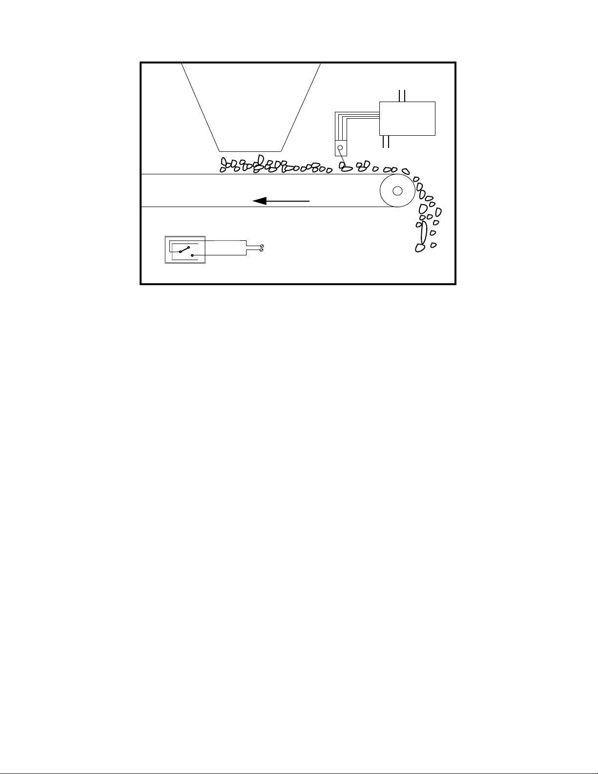
(An example of an external switch is a paddle-type flow switch that
monitors flow of material as shown in Figure 1. When material stops
flowing from the hopper, the flow switch inputs are closed and the controller
is enabled to begin the firing sequence. Whenever material is flowing from
the hopper, the flow switch inputs are opened and the controller is disabled;
the firing sequence is deactivated.)
To manually fire individual cannons, it is not necessary to program the
controller. The selected cannon fires when activated by the selector knobs on
the outside of the controller.
To automatically fire all cannons in a timed sequence, the controller must be
programmed for the desired number of air cannons to sequence (from 1 up to
10 air cannons) and the desired off-time (the length of time between each
cannon firing).
To automatically fire all cannons in a timed sequence when activated by an
external (flow) switch, the controller must be programmed as described
above, and the switch must be connected to the controller as follows:
• When connected to the controller’s ENABLE terminal block, the cannons
will fire in the programmed sequence (e.g., cannons 1 through 10 fire in
sequence) until the switch disables the controller and deactivates the firing
sequence. When the switch enables the controller again (activates firing),
the controller resets the sequence to begin with cannon 1 (e.g., if the switch
disabled the controller after firing cannon 3, the sequence will start by firing
cannon 1 the next time it is activated).
Introduction

Martin Engineering M4097-05/18 2Martin®Air Cannon Controller - multiple circuit
Figure 1. Flow switch inputs open, controller disabled
References The following documents are referenced in this manual:
• American National Standards Institute (ANSI) z244.1-1982, American
National Standard for Personnel Protection - Lockout/Tagout of Energy
Sources - Minimum Safety Requirements, American National Standards
Institute, Inc., 1430 Broadway, New York, NY 10018.
• Federal Register, Volume 54, Number 169, Part IV, 29 CFR Part 1910,
Control of Hazardous Energy Source (Lockout/Tagout); Final Rule,
Department of Labor, Occupational Safety and Health Administration
(OSHA), 32nd Floor, Room 3244, 230 South Dearborn Street, Chicago,
Illinois 60604.
•The National Electrical Code (NEC), National Fire Protection Association,
1 Batterymarch Park, P.O. Box 9101, Quincy, MA 02269-9101.
Safety All safety rules defined in the above documents and all owner/employer safety
rules must be strictly followed when working on this equipment.
Material required Only standard hand tools are required to install this equipment.
Controller
Power in
Out to air
cannons (1–10)
Flow
switch
Belt travel
Flow switch
ENABLE
(+124)
(ENABLE)
Introduction

Martin Engineering M4097-05/18 3Martin®Air Cannon Controller - multiple circuit
Before Installing Controller
1. Remove controller from shipping box.
2. If anything is missing or damaged, contact Martin Engineering or a
representative. Keep any damaged goods subject to examination.
WARNING
!
Before installing equipment, lock out/tag out energy source to
hopper, conveyor, and/or conveyor accessories.
3. Turn off and lock out/tag out energy source according to ANSI standards
(see “References”).
WARNING
!
If equipment will be installed in an enclosed area, test gas level
or dust content before using a cutting torch or welding. Using
a cutting torch or welding in an area with gas or dust may
cause an explosion.
4. If using a cutting torch or welding, test atmosphere for gas level or dust
content.
Before Installation

Martin Engineering M4097-05/18 4Martin®Air Cannon Controller - multiple circuit
Installing Controller
To install the controller, follow the procedures in this manual corresponding
to the following steps:
1. Mount the controller enclosure on a wall.
2. Wire individual air cannon solenoids to controller or, if air cannons are
wired to a solenoid enclosure, wire solenoid enclosure to controller.
3. If using an external flow switch, wire dry contact to controller.
Mounting
enclosure
WARNING
!
All electrical work must be done to National Electrical Code
(NEC) standards.
1. Determine location for controller.
CAUTION
!
Do not mount controller in area subject to shock, vibration,
temperatures exceeding 130°F (55°C), or explosion. Damage
to controller circuitry could result.
2. Mount onto wall with fasteners.
3. Drill conduit holes in controller enclosure for solenoid and power wires.
Use care not to damage internal components. Drill in most weather-proof
location available on enclosure.
4. Using electrical connectors, route wires from solenoid valves to
controller enclosure.
Installation

Martin Engineering M4097-05/18 5Martin®Air Cannon Controller - multiple circuit
Figure 2. Terminal Block Layout
Wiring air cannon
solenoids to
controller
NOTE
Only wiring required is power wire to controller and
N terminals on controller’s printed terminal strip.
1. Connect wires from air cannon solenoids to terminal strip outputs 1
through 10 and N terminals (see Figure 2). Connect number 1 solenoid to
1 supply and N, number 2 solenoid to 2 supply and N, etc. Continue until
all solenoids are connected.
2. Connect ground wire from each solenoid to controller enclosure. Route
power wire (115 VAC, 60 Hz) into controller enclosure.
3. Connect power safety ground wire to terminal block labeled GND.
4. Connect power wires to terminal blocks labeled 110V and COM. Connect
phase to 110V and neutral to COM.
5. Ensure ENABLE jumper is in place.
Fuse
Solenoid Ground
Terminals
Input Power Terminals
TERMINAL BLOCK NOTES:
1) ACTUAL COUNT OF COMMON TERMINALS
MAY BE LESS THAN SHOWN.
2)UNMARKED TERMINALS DO NOT REPRESENT
ACTUAL COUNT OF UNUSED SPARES.
Terminals
ENABLE
Jumper Wire
Installation

Martin Engineering M4097-05/18 6Martin®Air Cannon Controller - multiple circuit
Figure 3. Air Cannon Inputs
NOTE
PLC uses an octal numeral system.
6. Determine number of air cannons to be controlled.
7. Move “+124” wire (A) to terminal number (1—10) that corresponds with
number of air cannons to be controlled. For example, to use ten air
cannons connect “+124” wire to 10 as labeled.
8. If using an external flow switch, follow the procedure under “Wiring
external flow switch to controller.” If not, follow the procedures under
“After installing controller.”
Wiring external
flow switch to
controller
WARNING
!
Before making any connections, lock out/tag out electrical
supply to controller according to ANSI standards (see
“References”).
NOTE
See Figure 2. ENABLE always resets the controller to cannon 1
while material flows. See “Overview of controller operation”
under “Introduction” for more information.
2. To use ENABLE, do the following:
a. Remove factory-installed jumpers between ENABLE terminal blocks.
b. Connect external flow switch dry contact to ENABLE terminals.
c. Connect external flow switch ground to controller.
A
Installation

Martin Engineering M4097-05/18 7Martin®Air Cannon Controller - multiple circuit
After Installing Controller
Manually firing
air cannons
1. To manually fire cannons 1 through 10, turn selector knob on door of
controller enclosure to number of cannon you wish to fire. Turn
HAND-OFF-AUTO knob to HAND (see Figure 4), hold for 1 second, and
release. (Selected cannon will fire and knob will return to OFF
automatically.)
2. When finished with manual firings, return selector knob to O. (This
disconnects the manual mode, and prevents accidental firing if the
HAND-OFF-AUTO switch is turned to HAND.)
Figure 4. Air Cannon Controller Door
After Installation

Martin Engineering M4097-05/18 8Martin®Air Cannon Controller - multiple circuit
Programming Controller
NOTE
Before programming the control system, determine the
number of air cannons to be controlled and the off time
between firings.
Figure 5. Off Time Selection
12
3
4
5
6
Off Time
Off Time
Off Time
Off Time
Off Time
Off Time
Off time between firings
Cannon #1
Cannon #2
Cannon #3
Cannon #4
Cannon #5
Cannon #6
Programming Controller

Martin Engineering M4097-05/18 9Martin®Air Cannon Controller - multiple circuit
Figure 6. Display Screen Functions
Figure 7. Main Display Screen
Button Function
ESC Cancels the current operation, and returns to the immediately
preceding operation.
Scrolls up the menu or increments the selected number.
Scrolls down the menu or decrements the selected number.
OK Goes into each control screen or enters the current operation.
Programming Controller

Martin Engineering M4097-05/18 10 Martin®Air Cannon Controller - multiple circuit
Figure 8. Air Cannon Off Time Screens
Figure 9. Inputting Off Time
Setting off time 1. To change off time value:
a. Navigate to desired air cannon.
b. Press and hold “OK” button until the time value flashes.
c. Using the left and right arrow buttons navigate to the desired digit.
d. Use the up and down arrow buttons to change the value.
e. Press “OK” button to enter value.
Off Time in Seconds
(factory default is 900)
Press up and down arrow keys
to view all air cannon off times
Programming Controller

Martin Engineering M4097-05/18 11 Martin®Air Cannon Controller - multiple circuit
Parts Numbers
Figure 10. Martin®Air Cannon Controller - multiple circuit, P/N 38901
Item Description Part No. Qty
1 Air Cannon Controller NEMA 4 38901 1
2 Martin Products Label 38048 1
3 Operator Manual M4097 1
1
2
Part Numbers

Martin Engineering M4097-05/18 12 Martin®Air Cannon Controller - multiple circuit
Note: All dimensions are given in inches (mm) and are for reference only.
Figure 11. Air Cannon Controller Dimensions
8.14
(207) 12.16
(309)
8.00
(203)
14.38
(365)
13.31
(338)
Part Numbers

Any product, process, or technology described here may be the subject of intellectual property rights reserved by
Martin Engineering Company. Trademarks or service marks designated with the ® symbol are registered with the U.S.
Patent and Trademark Office and may be proprietary in one or more countries or regions. Other trademarks and
service marks belonging to Martin Engineering Company in the United States and/or other countries or regions may
be designated with the “TM” and “SM” symbols. Brands, trademarks, and names of other parties, who may or may
not be affiliated with, connected to, or endorsed by Martin Engineering Company, are identified wherever possible.
Additional information regarding Martin Engineering Company’s intellectual property can be obtained at
www.martin-eng.com/trademarks.

Martin Engineering USA
One Martin Place
Neponset, IL 61345-9766 USA
800 544 2947 or 309 852 2384
Fax 800 814 1553
www.martin-eng.com
For nearly 20 years, Martin Engineering’s Foundations™ Books have taught industry
personnel to operate and maintain clean and safe belt conveyors. The Foundations™
Book, fourth edition, focuses on improving belt conveyors by controlling fugitive material.
“The Practical Resource for Total Dust and Material Control,” is a 576-page hard cover
volume that provides information of value to industries where the efcient handling of bulk
materials is a key to productivity and protability.
Expanding upon the book, our Foundations™ Training Program addresses the design
and development of more productive belt conveyors, and is offered in three customizable
seminars. Attendees gain a better understanding of conveyor safety and performance,
helping to justify upgrade investments and increase protability.
Form No. M4097-05/18 © Martin Engineering Company 2018
Table of contents
Other Martin Industrial Equipment manuals