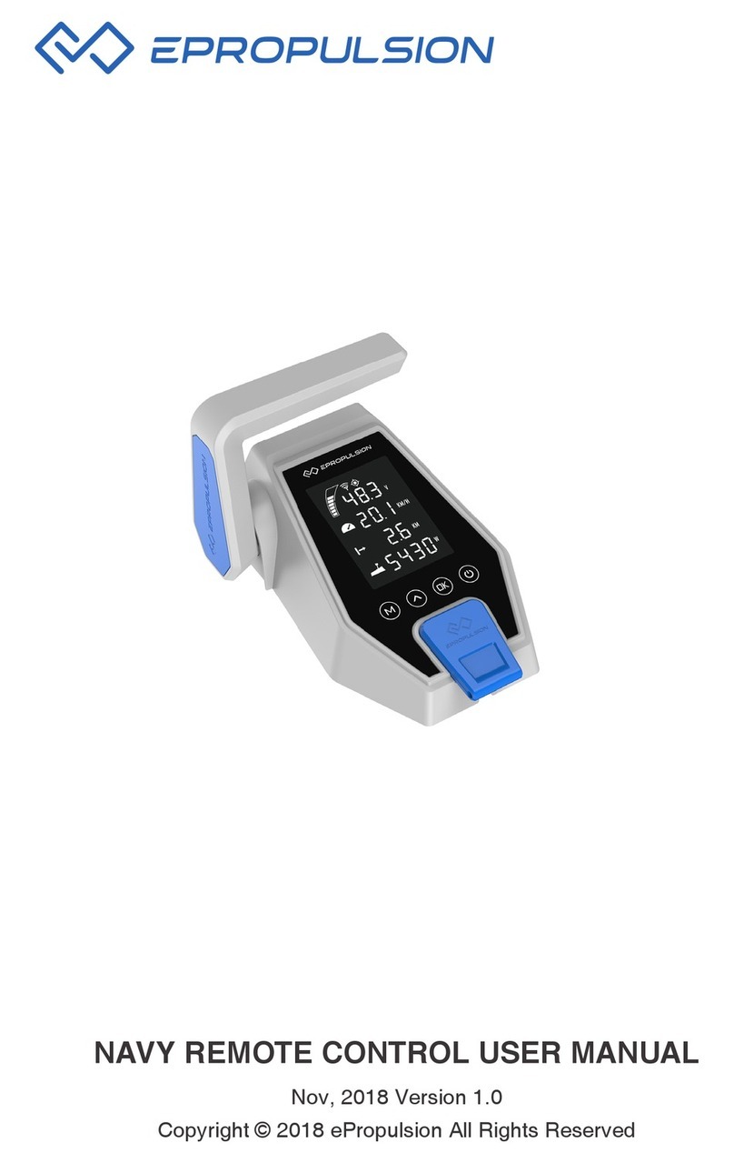
ePropulsion Evo Dual User manual

Evo Dual Remote Control User Manual
2021.04 Version 1.0
Copyright © 2021 ePropulsion All Rights Reserved
English


1
English
Acknowledgement
Thanks for choosing ePropulsion products, your trust and support in our company are
sincerely appreciated. We are dedicated to providing high-performance products and
accessories.
Welcome to visit www.epropulsion.com and contact us if you have any concerns.
Using This Manual
Before use of the product, please read this user manual thoroughly to understand the
correct and safe operations. By using this product, you hereby agree that you have
fully read and understood all contents of this manual. ePropulsion accepts no liability
for any damage or injury caused by operations that contradict this manual.
Due to ongoing optimization of our products, ePropulsion reserves the rights of
constantly adjusting the contents described in the manual. ePropulsion also reserves
the intellectual property rights and industrial property rights including copyrights,
patents, logos and designs, etc.
This manual is subject to update without prior notice, please visit our website
www.epropulsion.com for the latest version. If you find any discrepancy between your
products and this manual, or should you have any doubts concerning the product or
the manual, please visit www.epropulsion.com.
ePropulsion reserves the rights of final interpretation of this manual.
This manual is multilingual, in case of any discrepancy in the interpretation of
different language versions, the English version shall prevail.
Symbols
The following symbols will help to acquire some key information.
Important instructions or warnings
Useful information or tips

2
Product Identification
Below picture indicates the serial numbers of Evo Dual Remote Control. Please note
the position of the serial numbers and record them for access to warranty service and
other after-sale services.
Figure 0-1
Figure 0-2
Model: Dual Remote Control
PORT
STBD
DISPLAY
Serial No.: DDRC1K90001
48V RS485
Serial No:
Model: Evo Display Panel

3
English
Table of content
Acknowledgement..................................................................................... 1
Using This Manual..................................................................................... 1
Symbols .................................................................................................... 1
Product Identification ................................................................................ 2
1 Product Overview ................................................................................... 4
1.1 In the Package ........................................................................................ 4
1.2 Specification............................................................................................ 5
1.3 Important Notes ...................................................................................... 5
1.4 Declaration............................................................................................... 6
2 Mounting................................................................................................ 7
2.1 Mounting the Throttle.............................................................................. 7
2.2 Connecting the Throttle .......................................................................... 7
2.3 Button Description................................................................................... 8
2.4 Calibration................................................................................................ 9
3 Display Panel........................................................................................ 11
3.1 Mounting the Display Panel.................................................................. 11
3.2 Display Panel ......................................................................................... 12
3.3 Dock Power Limited Setting ................................................................. 15
3.4 Preference Settings............................................................................... 17
3.5 Battery Configuration............................................................................ 19
4 Use of Kill Switch.................................................................................. 24
5 Warranty .............................................................................................. 25
5.1 Warranty Policies................................................................................... 25
5.2 Out of Warranty...................................................................................... 26
5.3 Warranty Claim Procedures.................................................................. 26

4
1 Product Overview
The Evo Dual Remote Control is used for starting and stopping the outboard motor,
adjusting the speed of the motor, configuring the battery parameters, displaying the
system information and messages, etc. The Evo Dual Remote Control is powered by
connecting to the outboard with a communication cable. When using the Evo Dual
Remote Control, it requires an additional steering wheel to help steer.
1.1 In the Package
When you receive a set of Evo Dual Remote Control, unpack its package and check
if all the items below are included in the package. If there is any loss or transport
damage, please contact your dealer immediately.
Items Qty./Unit Figure
Evo Dual Re-
mote Control
( Remote Main
Part)
1 set
Evo Display
Panel 1 piece
User Manual,
Warranty Card
& Invitation
Card
1 set
Warranty Fixing Guide
Kill Switch 2 pieces
Communicati-
on Cable 0.5m

5
English
1.2 Specification
Evo Dual Remote Control
Weight 2.6 kg / 5.7 lbs
Display 4.3"Independent Display
Communication Wired
Communication Distance ≤ 15 m
Dimensions 151.8 x 178 x 159.4 mm (Remote Main Part)
138.5 x 106.9 x 42.5 mm (Display)
1.3 Important Notes
1. Check the status of the Evo Dual Remote Control and battery level before each
trip.
2. Only adults who have fully read and understood this manual are allowed to
operate this product.
3. Make sure the Evo Dual Remote Control is properly installed before use.
4. Be familiar with the basic operation of this product before use, including start-up,
stop, control mode, and emergency stop.
5. Make sure that the function of this product is normal before each use.
6. Stop the motor immediately if someone falls overboard during the trip.

6
1.4 Declaration
Object of the declaration:
Product Description: Evo Dual Remote Control
Model: Evo Dual Remote Control
Company Name: Guangdong ePropulsion Technology Limited
Company Address: Room 201, Bldg.17A, 4th XinZhu Road, SongShan Lake District,
Dongguan City, Guangdong Province, China
The object of the declaration is in conformity with the following directives:
EMC-directive 2014/30/EU
Applied standards:
EN 55014-1:2017
EN 55014-2:2015
EN 61000-3-2:2014
EN 61000-3-3:2013
This device complies with part 15 of the FCC Rules: Operation is subject to the
following two conditions:
(1) This device may not cause harmful interference and,
(2) This device must accept any interference received, including
interference that may cause undesired operation.
Signature:
Shizheng Tao, Chief Executive Officer & Cofounder of
Guangdong ePropulsion Technology Limited

7
English
2 Mounting
2.1 Mounting the Throttle
Follow the fixing guide to fix the throttle of the Evo Dual Remote Control to the boat.
Figure 2-1
2.2 Connecting the Throttle
Please refer the label on the bottom of the Evo Dual Remote Control to connect
with the machine and the Evo Display Panel. The starboard side machine should be
connected with the STBD connector by a communication cable, and use right side
throttle to control it. The port side machine should be connected with the PORT
connector by a communication cable. The Evo Display Panel should be connected
with the DISPLAY connector.
Figure 2-2
Model: Dual Remote Control
PORT
STBD
DISPLAY
Serial No.:

8
Figure 2-3
2.3 Button Description
Button Function
Power button
1.After connecting the dual remote control properly, power on
the outboard. Long press the power button, beep means the
dual remote control is turned on successfully.
2.When the dual remote control is turned on, long press the
power button, beep means the dual remote control is turned
off successfully.
NORM
Normal mode
1.When the dual remote control is turned on, press the NORM
button, beep once means it is switched to normal mode wi-
thout power limited.
2.When the dual remote control is in the normal mode, long
press NORM button for 5 seconds, beep once means it enters
the calibration mode.
CAN-IN CAN-OUTMOTOR
CAN-IN CAN-OUTMOTOR
Remote
Switch
Communication
Terminator
Dual
Remote
Control
Display
Panel

9
English
Button Function
SYNC
Synchronization
mode
1.When it is turned on, press SYNC button, beep once means
it is switched to synchronization mode and the SYNC button
light is on.
2.When it is in the synchronization mode, long press SYNC but-
ton, beep once and the DOCK button light blinks three times. It
means that it is switched to the mode that two machines are
controlled by right side throttle handle. Then long press SYNC
button again, beep once and it is switched to the mode that
two machines are controlled by left side throttle handle. These
two modes can be switched to each other.
When under the synchronization mode, the machines are
controlled by right side throttle handle by default.
DOCK
Dock mode
When it is turned on, press DOCK button, beep once and it is
switched to dock mode. The DOCK button light is on and the
power is limited to 50%.
2.4 Calibration
Calibration process Figure
Step 1: When the throttle handle is on the
zero position as shown in figure 2-3, long
press "NORM" button for 5 seconds to
enter calibration mode. Push the throttle
handle forward to the maximum position
as shown in figure 2-2, and press the
"NORM" button to confirm.
Push forward to the
end then press NORM
Step 2: Pull the throttle handle back to
the zero position as shown in figure 2-3,
and press the "NORM" button to confirm.
Pull to the neutral
then press NORM

10
Calibration process Figure
Step 3: Pull backward the throttle handle
to the maximum position as shown in
gure 2-4 and press the "NORM" button
to conrm.
Pull backward to the end
then press NORM
Step 4: Calibration complete. Successful Calibration
Figure 2-2 Figure 2-3 Figure 2-4
If the calibration fails or is not corrected, the NORM button light will blink and the
buzzer will sound, and "Calibration failed" will be displayed on the display panel,
which needs to be recalibrated.If the calibration is successful, the NORM button
light will be on and the buzzer will not sound.

11
English
3 Display Panel
3.1 Mounting the Display Panel
Follow the instructions below to fix the display panel of the Evo Dual Remote Control
to the boat.
1. Drill holes on the hull through the fixing guide referring to the figure 3-1.
Figure 3-1
2. Remove the trim.
3. Fix the display panel to the boat referring to the figure 3-2.
Figure 3-2
If a panel board thickness is between 2mm (0.08 in.) and 8mm (0.31 in.), please
use the supplied screws. If not, please purchase suitable screws separately.
130.6
99.2
117.5
82.7
2.9
6.6
3.5 X 4
2 X 4
M3 Tapping Screw
Trim

12
3.2 Display Panel
Buttons Functions
Power button
1. When the display panel is turned off, press and
hold the power button to power on the display
panel.
2. When the display panel is turned on, press and
hold the power button to power off the display
panel.
3. When the display panel is turned on, press the
power button to switch on or off the backlight.
Conrm button
1.On the main page, press the Conrm button
to switch the display between battery level or
battery voltage.
2.On setting pages, press the Conrm button to
save the current settings and when setting the
parameters, press Conrm button to switch to
the next item.
Select button
1.If connecting with NAVY outboards or Pod Dri-
ve 3.0/6.0, on the main page, press Select button
to change the unit of speed and distance.
2.On setting pages, press Select button to view
options for current setting, or adjust congurati-
on parameters.
Menu
1. In power-on state, long press the Menu button
to enter the preference setting page.
2. On setting pages, press Menu button to return
to the home page or previous page.
Please attached the kill switch properly before turning on the display panel,
otherwise the display panel will display “Equipment offline”.
All operations on the display panel need to be done in power-on state.
If users enter the page without setting any parameters, the current parameters
displayed on the page will be saved as user parameters by default.

13
English
Icons Functions
Battery level
indicator Indicating battery level.
100%
48.0V
Battery voltage /
level
48.0V : indicates current battery voltage.
100% : indicates current battery level.
Hydrogeneration
indicator
The machine can turn on or off the hydro generati-
on function on the preference page if it supported
this function.
Shown constantly: the hydro generation function
is turned on.
Blink: the machine is charging the battery.
Hidden: the hydro generation function is turned
off.
GPS status indi-
cator
Hidden: no satellite signal is received or GPS does
not work.
Blink: GPS is connecting to satellites.
Shown constantly: GPS is in use.
If connect with SPIRIT 1.0 or Pod Drive 1.0, GPS
status indicator will be always hidden.
Motor over-heat
alert
Hidden: system temperature is in normal range.
Blink: system temperature is a little high and the
maximum input power of motor has been lowered
than rated maximum power.
Shown constantly: system is over temperature
and the outboard will stop working. The outboard
motor can’t be started until the system tempera-
ture drops to a certain level.
Controller
over-heat alert
Hidden: system temperature is in normal range.
Blink: system temperature is a little high and the
maximum input power of motor has been lowered
than rated maximum power.
Shown constantly: system is over temperature
and the outboard will stop working. The outboard
motor can’t be started until the system tempera-
ture drops to a certain level.

14
Icons Functions
Fan fault Hidden: fan works normally.
Blink: fan has faults.
Throttle reset
indicator
A blinking "RESET" indicating the throttle should
be reset to the neutral position.
3000
W
Throttle power Displaying real time input power to the system.
Current speed
Displaying real time cruising speed.
Set units (KM/H, MPH or KNOTS) in preference
setting page.
If it is connected with SPIRIT outboards or pod
drive 1.0, it will display the ePropulsion logo.
6000
RPM
Rotational speed Displaying real time motor rotational speed.
Throttle gear
: forward gear
: neutral gear
: backward gear
Kill switch status
indicator
Hidden: kill switch is well attached and works
well.
Shown constantly: the kill switch is detached.
Travelled distan-
ce/time or remai-
ning distance/
time
: Remaining distance or time that outboard can
travel.
: Travelled distance or time.
Time display Displaying real time travel time.
Distance display
Displaying remaining distance that outboard can
travel or travelled distance
Set units (MILE, KM (kilometer) and NM (nautical
mile)) in preference setting page.
KM/H
0.5

15
English
3.3 Dock Power Limited Setting
Dock Power Limited Setting Process LCD Displaying
Step1: In power-on state, long press the
Menu button to enter the Port or Star-
board Side Setting page, and press Select
button the select Port or Starboard Side.
Then press Conrm button to enter the
Setting page.
Port Side
Starboard Side
Step2: Press Select button to switch to
Dock Power Limit, then press Conrm
button to enter the Dock Power Limit
page.
Port Side
Dock Power Limit
Unit Setting
Battery Setting
Step3: Use the Select button to select
the power you want to set. "Forward" is
the forward power and "Backward" is
the backward power. Press the Conrm
button to enter this power limit option.
Port Side
Forward Limit: 01 %
01 %Backward Limit:
Step4: Please set the two-digit value
from left to right through the Select but-
ton. Each time you set a value, press the
Conrm button to move to the next digit.
The ashing value is the value being
edited. The power is limited to 1%-50%.
Port Side
Forward Limit:
01 %Backward Limit:
01 %

16
Dock Power Limited Setting Process LCD Displaying
Step 5: After setting all the values of
the forward power limit, press the Menu
button to return, and press the select but-
ton to select the backward power limit
option. After the forward and backward
power limits are set, press the Menu
button to return to the preference setting
page, and the setting parameters are
automatically saved.
Port Side
Dock Power Limit
Unit Setting
Battery Setting

17
English
3.4 Preference Settings
It is recommended to refer the steps below to set the displaying preference before
operating the dual remote control
Preference Settings Process LCD Displaying
Step1: In power-on state, long press the
Menu button to enter the Port or Star-
board Side Setting page, and press Select
button the select Port or Starboard Side.
Then press Conrm button to enter the
Setting page.
Port Side
Starboard Side
Step2: Press the Select button to switch
to "UnitSetting". Press the Conrm button
to enter the unit setting page.
Port Side
Dock Power Limit
Unit Setting
Battery Setting
Step3: Press the Select button to choose
the unit you want to display.
"Battery" is the battery power and voltage
display selection. "Distance Unit" is the
choice of distance unit; "Speed Unit" is
the choice of speed unit.
Through the Select button, select the unit
to be displayed, and press the Conrm
button to conrm. White text on a black
background is selected. Press the Menu
button to return to previous setting page.
Port Side
Battery:
Speed Unit:
Distance Unit:
SOC Volt
MPH
MILE
KM/H
KM
KNOTS
NM

18
Preference Settings Process LCD Displaying
Step4: Press the Menu button to return to
preference setting page.
Port Side
Dock Power Limit
Unit Setting
Battery Setting
Other manuals for Evo Dual
1
Table of contents
Other ePropulsion Remote Control manuals
