EPS MULTIBOOST 350L Simplicity Slimline Fixed Speed... User manual

MULTIBOOST
O & M Manual Rev 4
Integrated Sanic
UV System
Multiboost Installation
& Dos & Donts

2
Contents
Declaration of Conformity 3
Directives & National Implementation Provisions
4
Multiboost Range 5
Delivering, Handling and Storing 7
Installation Guide & Schematics 8
Key Features 13
Drip Trays 14
Electrical 15
Pump Type & Control Information 16
Fixed Speed - Preso Multi Controls 17
Preso Multi 18
Preso Vario 19
Steadypres 20
Anti Vibration Mat 22
Insulation Jacket - Foil back 23
Insulation Jacket - Black 24
Dimensions 25
Components 26
Errors and omissions excepted

3
We, EPS Group
of Mallow Business and Technology Park
Quartertown
Mallow
Co Cork P51 AC94
Telephone: +353 (22) 31200
Fax: +353 (22) 31250
Email: info@epswater.com
in accordance with the following Directives:
Refer to page 2 for list of directives
Hereby declare that:
Equipment: Multiboost Range
Model : Refer to page 5 for complete range of models & product codes
is in conformity with the applicable requirements of the following documents:
Refer to page 4 for list of national implementation provisions
I hereby declare that the equipment above has been designed and assembled to comply with
the relevant section of the above referenced specications. The unit complies with all applicable
Essential Requirement of the Directives.
The Technical Construction File is maintained at:
EPS Group
Mallow Business and Technology Park
Quartertown
Mallow
Co Cork P51 AC94
Telephone: +353 (22) 31200
Email: info@epswater.ie
DECLARATION OF CONFORMITY
PLEASE KEEP THIS DOCUMENT IN A SAFE PLACE
Signed:
Managing Director, EPS
Date:
Declaration of Conrmity
March 2019

4
4
Pump Range Provisions
EN 60335-1
Top Multi EN60034-1
Top Multi-Tech IEC 60335-1
NK IEC 60334-1
UP CIE 61-150
CIE 2-3
Fitting Type Provisions
Nylon Fittings
EN 60335-1
Pipe Type Provisions
MDPE Blue Pipe
AS/NZS 4020
BS EN 12201-2
BS EN 1717:2000
BS EN 12201
Valve Type Provisions
Check Valve EN 1717:2000
Flow Valve BS 1212/1
Fill Valve
WRAS Approved 1203001
Tank Type Provisions
Holding Tank BS 6920-1:2000
Controllers Directives
Steadypres
2006/95/CEE Low Voltage Directive
2002/95/CEE Dangerous substances in electromagnetic compliances (RoHS)
2002/96/CEE e 2003/108/CEE Dangerous substances in electronic appliances (WEEE)
2004/108/CE Electromagnetic Compatibility Directive(EMC)
EN 5501-1 (emissions)
Provisions
EN 61000-3-2 (emissions)
EN 61000-3-3 (emissions)
EN 55014-2 (immunity)
EN 61000-4 (immunity)
Preso Multi
Directives
2006/95/CEE Low Voltage Directive
2002/95/CEE Dangerous substances in electomagnetis compliances (RoHS)
2002/96/CEE e 2003/108/CEE Dangerous substances in electronic appliances (WEEE)
2004/108/CE Electromagnetic Compatibility Directive(EMC)
Provisions
EN 60730-2-6
EN 61000 6-3
Sealant Type Provisions
Thread Sealant
WRAS Approved
Certied NSF P1. sealant paste“green”, no risk phrases, blank MSDS
Directives & National Implementation Provisions

5
5
Product
Code Model Type Volume
[L]
Length
[MM]
Width
[MM]
Height
[MM]
Inlet
[Inch]
Outlet
[Inch]
Over-
o w
[Inch]
Drain
o ff
[Inch]
Weight
(Empty
Tank)
(kg)
1019648 MULTIBOOST 125L Compact
Fixed Speed 125 560 490 850 3/4" BSP 1" BSP 1¼" BSP 1" BSP 30
1028178 MULTIBOOST 125L Compact
-Fixed Speed 125 560 490 850 3/4" BSP 1" BSP 1¼" BSP 1" BSP 30
1012150 MULTIBOOST 200L Slimline
-Fixed Speed 200 584 584 1190 1/2" BSP 1" BSP 1" BSP 1" BSP 26
1001906 MULTIBOOST 350L Slimline
-Fixed Speed 350 584 584 1580 1/2" BSP 1" BSP 1" BSP 1" BSP 29
1001909 MULTIBOOST 250L Utility
Fixed Speed 250 760 760 1033 1/2" BSP 1" BSP 1" BSP 1" BSP 28
1012151 MULTIBOOST 250L Utility
Variable Speed 250 760 760 1033 1/2" BSP 1" BSP 1" BSP 1" BSP 35
1001911 MULTIBOOST 450L Utility
Fixed Speed 450 760 760 1393 1/2" BSP 1" BSP 1" BSP 1" BSP 35
1001916 MULTIBOOST 750L Utility
Fixed Speed 750 760 760 2113 1/2" BSP 1" BSP 1" BSP 1" BSP 46
1012152 MULTIBOOST 750L Utility
Variable Speed 750 760 760 2113 1/2" BSP 1" BSP 1" BSP 1" BSP 53
Multiboost Range
Product
Code Model Type Volume
[L]
Length
[MM]
Width
[MM]
Height
[MM]
Inlet
[Inch]
Outlet
[Inch]
Over-
o w
[Inch]
Drain
o ff
[Inch]
Weight
(Empty
Tank)
(kg)
1031919 MULTIBOOST 350L Simplicity
Slimline
Fixed Speed (Vario) 350 584 584 1260 ½”BSP 1” BSP 1” BSP 1” BSP 29
1033476 MULTIBOOST 450L Simplicity
Utility - Fixed Speed (Vario) 450 760 760 1300 ½” BSP 1”BSP 1”BSP 1” BSP 35
1036386 MULTIBOOST 200L Simplicity
Rectangular - Fixed Speed
(Vario) 200 1106 475 540 ½”BSP 1” BSP 1” BSP 1” BSP 20
1033898 MULTIBOOST 270L Simplicity
Rectangular - Fixed Speed
(Vario) 270 1571 475 521 ½”BSP 1” BSP 1” BSP 1” BSP 29
1033899 MULTIBOOST 300L Simplicity
Rectangular - Fixed Speed
(Vario) 300 1029 664 710 ½”BSP 1” BSP 1” BSP 1” BSP 29
1033900 MULTIBOOST 500L Simplicity
Rectangular - Fixed Speed
(Vario) 500 1190 720 720 ½”BSP 1” BSP 1” BSP 1” BSP 34
1081647 MULTIBOOST 345L Simplicity
Rectangular - Fixed Speed
(Vario) 345 1571 475 632 ½”BSP 1” BSP 1” BSP 1” BSP 34
1070476 MULTIBOOST 455L Simplicity
Rectangular - Fixed Speed
(Vario) 455 1765 580 616 ½”BSP 1” BSP 1” BSP 1” BSP 34
Pres o Vario System
Pres o Multi System
• Please ensure that Multiboost Vario is tted with the correct rated RCBO on incoming electrical supply
• Please ensure that the Preso Multi system is tted with the correct rated RCBO on incoming electrical supply

6
6
Product
Code Model Type Volume
[LTR]
Length
[MM]
Width
[MM]
Height
[MM]
Inlet
[Inch]
Outlet
[Inch]
Over-
o w
[Inch]
Drain
o ff
[Inch]
Weight
(Empty
Tank)
(kg)
1028679 MULTIBOOST 650L Utility
Fixed Speed 650 1083 669 1083 ½" BSP 1" BSP 1" BSP 1" BSP 63
1001925 MULTIBOOST 1000L Utility
Fixed Speed 1000 1688 563 1444 ½" BSP 1" BSP 1" BSP 1" BSP 63
1019276 MULTIBOOST 250L Bunded
Fixed Speed (Auto) 250 760 760 1478 ½" BSP 1" BSP 1" BSP 1" BSP 45
1028680 MULTIBOOST 650L Bunded
Fixed Speed (Auto) 650 752 1200 1174 ½" BSP 1" BSP 1" BSP 1" BSP 45
1021452 MULTIBOOST 270L
Rectangular Utility
Fixed Speed (Auto Tech) 270 1574 475 520 ½" BSP 1" BSP 1" BSP 1" BSP 29
1036388 MULTIBOOST 200L
Rectangular Utility
Fixed Speed (Preso) 200 1106 475 540 ½" BSP 1" BSP 1" BSP 1" BSP 20
1036439 MULTIBOOST 270L
Rectangular Utility
Fixed Speed (Preso) 270 1571 475 520 ½" BSP 1" BSP 1" BSP 1" BSP 29
1017488 MULTIBOOST 300L
Rectangular Utility
Fixed Speed 300 1045 665 710 ½" BSP 1" BSP 1" BSP 1" BSP 29
1017490 MULTIBOOST 500L
Rectangular Utility
Fixed Speed 500 1190 720 800 ½" BSP 1" BSP 1" BSP 1" BSP 34
1017488 MULTIBOOST 300L
Rectangular Multi Fixed
Speed (Preso) 300 1045 665 710 ½” BSP 1” BSP 1”BSP 1” BSP 29
1070476 MULTIBOOST 455L
Rectangular Multi Fixed
Speed (Preso) 455 1765 616 580 ½” BSP 1” BSP 1”BSP 1” BSP 34
Multiboost Range
Product
Code Model Type Volume
[LTR]
Length
[MM]
Width
[MM]
Height
[MM]
Inlet
[Inch]
Outlet
[Inch]
Over-
o w
[Inch]
Drain
o ff
[Inch]
Weight
(Empty
Tank)
(kg)
1019649 MULTIBOOST 125L Compact
Variable Speed 125 560 490 850 3/4" BSP 1" BSP 1¼" BSP 1" BSP 34
1001905 MULTIBOOST 300L Slimline
Variable Speed 300 584 584 1580 1/2" BSP 1" BSP 1" BSP 1" BSP 36
1001912 MULTIBOOST 500L Utility
Variable Speed 500 760 760 1393 1/2" BSP 1" BSP 1" BSP 1" BSP 42
1012153 MULTIBOOST 1000L Utility
Variable speed 1000 1688 563 1444 ½" BSP 1" BSP 1" BSP 1" BSP 70
1019650 MULTIBOOST 250L Bunded
Variable Speed 250 760 760 1478 ½" BSP 1" BSP 1" BSP 1" BSP 53
Steadypres VSD System
Pres o Multi System
Weight
• Please ensure that Preso Multi system is tted with the correct rated RCBO on incoming electrical supply
• Please ensure that the Steadypres is tted with the correct rated MCB on incoming electrical supply

7
7
Delivery and Handling
The Multiboost system is supplied from the factory, as an all-in-one packaged water boosting
system. The weight and size of the Multiboost (depending on model chosen) may require
the aid of lifting equipment and if so, must be handled in a safe and proper manner to
avoid causing unnecessary damage to the unit and/or individual/s. In the event that lifting
equipment is used, please follow widely accepted safe lifting procedures.
Inspection
On delivery, the Multiboost should be inspected thoroughly and any damage must be
reported to the supplier in writing within 24/48 hours. Always ensure the Multiboost
inspection takes place prior to installation.
Applications
The Multiboost set is designed to be compact, with ease of installation, and to provide many
years of service for domestic pressure boosting and light commercial pressure boosting.
The Multiboost set should not be installed in areas that are classied as hazardous, where
an explosion could occur or people could be harmed or in an area of any potential leaks that
could cause damage to any person or property. The use of bunded tanks and/or a drip tray are
essential to any Multiboost being installed above ceiling level.
EPS accepts zero responsibility if the Multiboost is used to pump liquids that are considered
hazardous by touch, ingestion or inhalation of fumes or gases given o by the liquid, or any
damage caused to property where the recommended protection of a drip tray or use of
bunded tank was not adhered to.
Warranty
Your Multiboost system is covered by a 12 month warranty from the date of purchase. This
warranty covers all parts or material defects and will be replaced free of charge. Labour call
outs for warranty / repair will require a call out fee of €150 incl. VAT. This fee must be paid
up front to secure call out. If there is a warranty defect with the unit, it will be repaired /
replaced and your €150 will be refunded. If there is a defect outside EPS’ control (i.e. incorrect
installation) the €150 fee will not be refunded. The additional cost of replacement parts will be
administered in this situation also. EPS cannot carry out any tests, servicing or repairs on a unit
if the drip tray has not been tted as part of the unit being installed in the property.
Site Storage
Once a Multiboost has arrived on site and has been inspected, it is recommended that it is
stored away from sharp objects, in a safe place, on an even surface, free from moisture, dust,
sunlight and frost.
Pre Installation Checks
Please ensure the unit is tted and supported in the right manner. Check the unit for any visual
defects.
In accordance with the latest IEE regulation, all electrical connections should be carried out
by a qualied electrician. The Multiboost must be earthed. EPS strongly recommend that
a correctly sized RCBO for xed speed and MCB for variable speed units are tted on the
incoming electrical supply. If the installer is tting a plug, please ensure the correct fuse is
selected in relation to the pump selection ampage. Please see page 13 for more information.
Delivering, Handling and Storing
Multiboost Range
• Please ensure that Preso Multi system is tted with the correct rated RCBO on incoming electrical supply
• Please ensure that the Steadypres is tted with the correct rated MCB on incoming electrical supply

8
8
Installation Guide
Fill the storage tank with water through the ball cock. Please ensure the right ball cock is tted
for the corresponding pressure rating. High pressure and low pressure ball cocks available.
Installer to ensure and test the correct option is being used, as pressure diers between areas.
Make sure the electrical supply is fully isolated and cannot be turned on before working on
the pump, motor controller or any part of the unit.
Do not turn on electrical supply to the Multiboost without ensuring all electrical ttings and
all covers are intact and fully isolated from human touch during operation.
General Information
1. The discharge pipe from the controller must be, at minimum, the same size as the
Multiboost inlet supply; if it is smaller, it may result in reduced pressure and ow to the
outlets
2. The overow pipe that is tted should be twice the size of the inlet supply and should be
piped away to safe drainage zone. (It’s recommended that a full test is carried out by the
installer)
3. When being installed, the tank’s overow connection must be at least twice the internal
size of the supply pipe, taking into account the incoming pressure and ow. The
overow pipe must not be obstructed or restricted (no sharp elbows), factoring in the
distance being piped away to the drainage zone. The pipe should have an even, gradual,
straight slope to cope with the incoming pressure and ow. This pipe may have to be
further increased in size and EPS recommends the installer fully tests this system to
ensure that the overow pipe is capable and adequate to cope with the unlikely event of
a failure. The pipe size should be increased in proportion with the distance from the unit
to the drainage zone
4. The discharge pipe work must be properly secured so once the Multiboost is tted,
there is no stressed internal pipe work
5. Pipework installations should meet local water authority regulations
6. Electrical installation should meet the most recent issue of the IEE regulations and is
tted by a qualied person
7. Check that the cold water storage tank capacity is designed to meet your water
consumption demands and is suitable for the installation location
8. Drip tray or bunded tank must be included on every installation with correct overow
9. Please refer to Multiboost Commissioning Checklist as a guide
Recommendations
• Isolation valves tted before and after unit.
• Overow valve twice the size of the inlet supply valve.
• Pipe work easy to disassemble.
• Bunded tank/drip tray used for dwelling installations.
Water Quality
In the event that the water remains unused inside the tank for an extended period, it should
be drained and ushed to maintain water quality. This is recommended to ensure water
remains t for use year on year. There should be a drain o point at the end of each tank.
As required by any stored water arrangement, it is recommended that you disinfect and clean
the tank annually. Regular water samples should be taken periodically to check bacteria levels
(Recommended 2 tests per year).

9
9
We do not recommend installations in loft areas due to the weight of the tank and the increased
potential for damage in the event of a water leak or spillage. If the system must be installed
above ceiling level, it is highly recommended to use drip trays/bunded tank with the added
protection of an insulated jacket. Sound also travels very well through rafters and it is likely
that such an installation will be noisy compared to an installation on solid ground. Installations
higher than the mains water stop tap will reduce the rell rate of the tank.
1.
The Multiboost should be installed in a dry, well ventilated and frost free area where it is not
exposed to extreme temps. An ambient temperature of <20 °C is required to limit or reduce
bacteria growth. Multiboost may be located outdoors if in a weatherproof, frost and rodent
proof enclosure with adequate ventilation especially during warm weather
2. All pipe work that is exposed to freezing condition should be fully protected
3. Multiboost installation must be positioned properly for ease of access for examination and
service for compliance with health and safety practice
4.
EPS oer adequate facilities (Bunded Tank/Drip Tray) and protection from water damage in
the immediate location of the Multiboost
5.
1L of water = 1kg weight and the weight of the storage tank also. Please check load bearing
supports
6. There should be adequate lighting for service to be carried out safely
7. Where a Multiboost product is installed, it should be signed o by an approved engineer
and/or plumber/installer ensuring that the unit is installed in an appropriate location and
has all appropriate and required overows and protections in place and all of our guidelines
and recommendations have been considered. Please refer to Commissioning Checklist.
Foundation & Mounting
Multiboost must be mounted on a solid foundation to support the weight of the unit. Surfaces
must be at and level to spread weight load evenly. The recommended surface for Multiboost
is concrete plinth or oor. As previously stressed, EPS does not recommend installation of
Multiboost on wooden structures due the natural noise and vibration levels that travel along
it. When a pump is submerged in liquid, you are no longer dealing with decibel levels, but with
vibration levels. Please take the positioning of your Multiboost and the surrounding environment
into account.
Storage Tank
Multiboost is a cold water storage tank and must be installed in accordance with current
regulations. The quality of water in the storage tank should be potable and suitable for drinking.
However, it should be noted that the quality of stored water deteriorates over time if ambient
temperature is greater than 20 degrees Celsius (>20 °C). If the tank has been left idle for a length
of time, it is recommended that it is completely drained. At temperatures above 20 °C, the use of
a disinfection system (such as UV) is highly recommended.
Slave Tank & Bypass
EPS can provide an additional slave tank to cater for additional cold water storage demand and
they can be linked together. This allows for an increase in storage tank capacity for extra demand
that may occur. In the unlikely event of a Multiboost failure, it is recommended to install cold
water mains bypass to allow the water supply continue, at a reduced pressure, to the property.
This ensures a low pressure supply is available at all times while the unit is being repaired. The
bypass must be installed in accordance with the water bylaw regulations. The bypass should be
drained to prevent water stagnation if it is not being used.
Installation Guide
Installation Best Practice

10
10
Installation Guide
Information Label on each tank
Use of drip trays for installations over ceiling height is HIGHLY recommended
›Customer/installer to check unit for any
damage or leaks on delivery prior to
installation of unit
›Bunded tank or tank with drip tray
should be used for in-house installations
(depending on tank application & location)
›Tank installation above ceiling level is not
recommended. Unit’s ideal support base
is concrete due to weight. (i.e. 1L of water
= 1 kg)
›Unit to be fi tted in a safe place away from
any potential hazards & kept out of direct
sunlight
›Protective lid of tank to be installed over
control unit
›EPS is unable to service any unit installed
above ceiling level unless in accordance
with H&S regulations
›Unit to be installed by qualifi ed persons
only
›EPS recommends a by-pass valve be fi tted
on both the inlet & outlet in the unlikely
event of a pump failure
›Isolation shut-o valve to be fi tted
on supply & delivery side of tank (for
maintenance purposes
DO NOT REMOVE THIS LABEL
(Removal of this label will void warranty)
Inlet
Overfl ow
By-Pass Line
Typical example of installation
Rethinking Water
›The overfl ow pipe that is fi tted should be
twice the size of the inlet supply minimum (it
may have to be enlarged further, depending
on incoming pressure and fl ow) and should
be piped away to safe drainage zone. (It’s
recommended that a full test is carried out by
the installer).
›Overfl ow test to be completed after every
installation. This is to ensure the capacity of the
overfl ow pipe is able to handle any ballcock
failure, blockage or restriction. Ensure pipe is
not restricted & is laid straight with a su cient
fall without lags.
›The overfl ow pipe must not be obstructed or
restricted (no sharp elbows), factoring in the
distance being piped away to the drainage zone.
›Overfl ow/vermin screen needs to be cleaned
regularly to ensure removal of any impurities
present in the water.
›Pressure vessel air pre-charge to be checked
every 6 months (set 2lbs below cut-in pressure)
›High pressure ballcock fi tted as standard. (Low
range available on request)
›EPS recommends testing water for any
impurities or any water treatment required
›EPS accept no responsibility whatsoever for leaks
inside /outside of tank which are outside of our
control
ASSEMBLED BY: DATE:
INSTALLED BY: DATE: TEL:
MULTIBOOST
Scan for O&M Manual
or download on
Multiboost.ie
Scan for Multiboost O&M Manual
or download at Multiboost.ie
Fitting of a bypass unit & drip tray
with correct overflow capability is
highly recommended
Full overflow test is necessary on
every installation
Use of sharp elbows that may cause
flow restrictions is not recommended
The
MULTIBOOST
Range
C
M
Y
CM
MY
CY
CMY
K
Multiboost Stickers 4.pdf 1 08/02/2019 16:36:01
Water
Supply
Water
Delivery

11
11
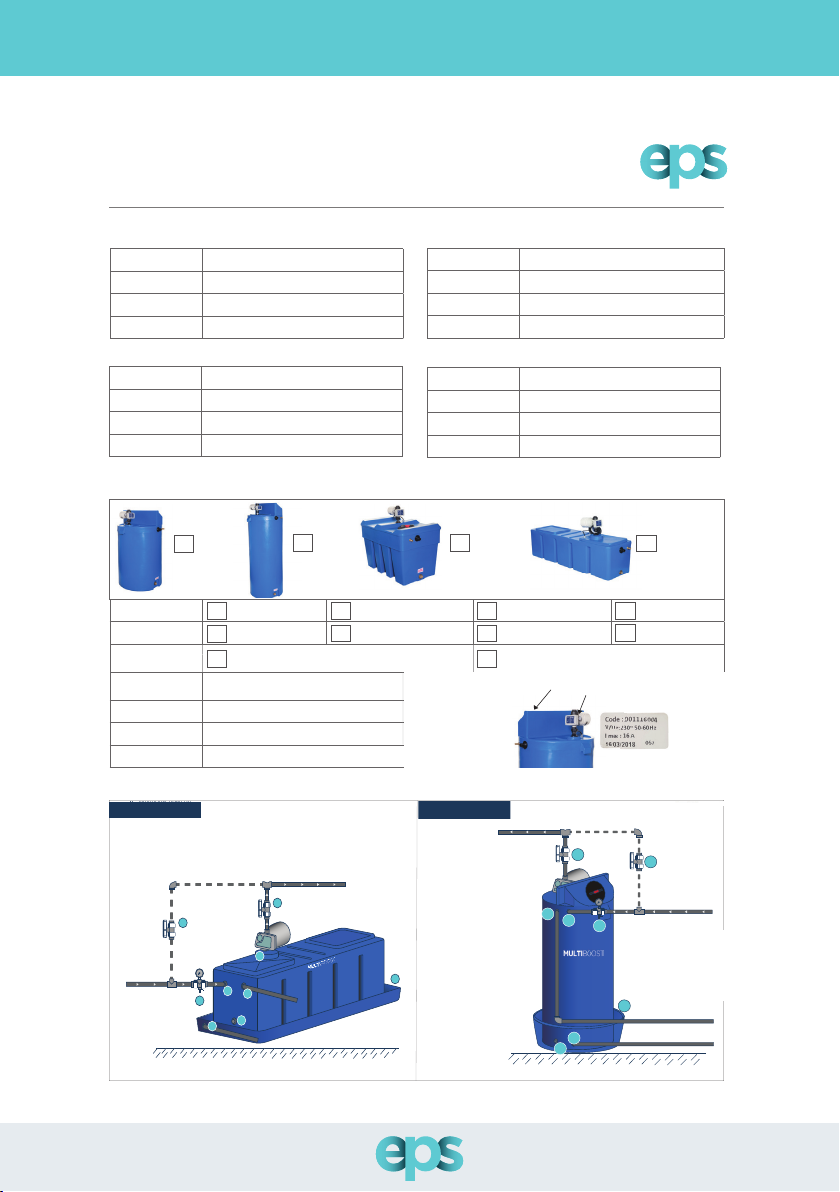
Installation Guide
Use of drip trays for installations over ceiling height is HIGHLY recommended
Installation Schematic
Bypass
Mains
Water Supply
Outlet Supply
2
3
7
3
8
56
4
1
1. Ball cock
Isolation valve with
pressure gauge
Bypass isolation valve
Separate Multiboost overflow
Separate drip tray over flow
Multiboost drain off
Drip tray
2.
3.
4.
5.
6.
7.
Removable lid with pump
8.
& controller inbuilt
Multiboost
200L, 270L, 345L and 455L
*EPS recommends the use of a drip tray and insulation jacket with every installation
Scan for Ball Cock
Performance Selection
Please note - Ball cock entry location (1) and tank overow connection (4) can be modied
to suit diering applications if required.

12
12
Installation Schematic
Bypass
Mains
Water Supply
Overflow to drain from tank
Overflow to drain from drip tray
Outlet
3
3
6
7
5
2
1
4
*EPS recommends the use of a drip tray and insulation jacket with every installation
1. Ball cock
Isolation valve with
pressure gauge
Bypass isolation valve
Multiboost overflow
Multiboost drain off
Drip tray
2.
3.
4.
5.
6.
Drip tray overflow7.
Multiboost
200L, 350L, 450L, 750L
Scan for Ball Cock
Performance Selection
13
13
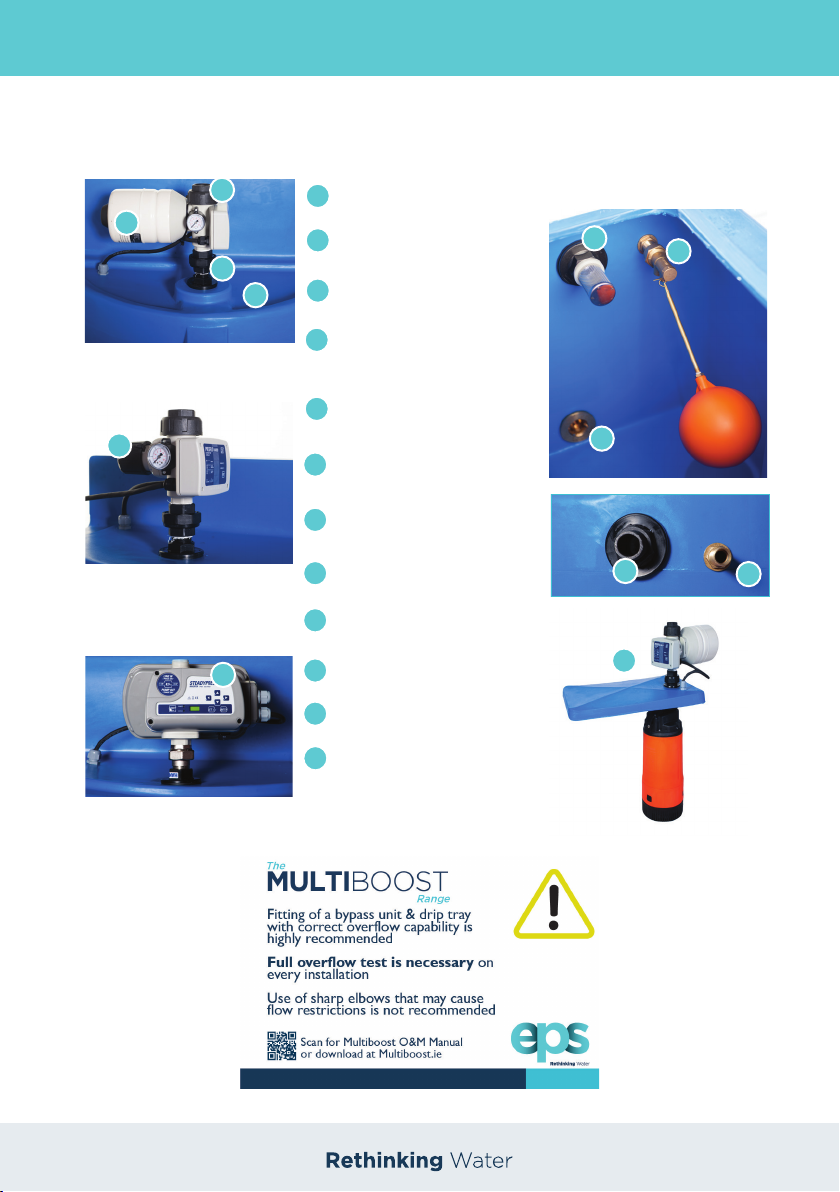
Key Features
1
2
1
Pressure Vessel (Preso Multi Version Only)
2
Removal union to access ow valve
3
Split union for easy maintainance
4
Drip tray built in to mould
(Selected models only)
4
3
5
Easy adjustable cut in pressure function
6
Variable speed option available
5
7
Vermin screen
7
8
Ball cock unit & oat
8
9
Drain o facility to clean tank
9
10
Overow
11
Inlet water supply
10 11
6
12
Total Removal Design of Pump and
Controller System (2018Version)
200L & 270L Rectangular Versions Only
12
Presflo Multi
Vario
Steadypres VSD
Key Features
Installation Schematic
14
14
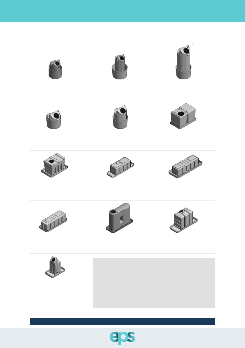
Drip Trays
Multiboost Rectangular Tray: 200L
›Height: 80mm
›Width: 515mm
›Length: 1648mm
›Product Code: 1033640
1
1
2
2
3
3
4
4
5
5
6
6
A A
B B
C C
D D
E E
F F
STBL00300V
190mm Lid + 1" Connection
Height: 1422mm
STBL00450V
285mm Lid + 1" Connection
Height: 1285mm
STBL00250V
285mm Lid + 1" Connection
Height: 925mm
STBL00750V
285mm Lid + 1" Connection
Height: 2005mm
STBL00200V
190mm Lid + 1" Connection
Height: 1035mm
EPS - Tanks & Drip Trays
Rev N o: R1.0
Rev D ate : 0 8-0 2-2 019
Appr ove d By : J S - SW
1
1
2
2
3
3
4
4
5
5
6
6
A A
B B
C C
D D
E E
F F
STBL00300V
190mm Lid + 1" Connection
Height: 1422mm
STBL00450V
285mm Lid + 1" Connection
Height: 1285mm
STBL00250V
285mm Lid + 1" Connection
Height: 925mm
STBL00750V
285mm Lid + 1" Connection
Height: 2005mm
STBL00200V
190mm Lid + 1" Connection
Height: 1035mm
EPS - Tanks & Drip Trays
Rev N o: R1.0
Rev D ate: 08-0 2-2 019
Appr ove d By : JS - SW
1
1
2
2
3
3
4
4
5
5
6
6
A A
B B
C C
D D
E E
F F
STBL00500R
285mm Lid + 1" Connection
STBL00300R
190mm Lid + 1" Connection
STBL00200R
One Lid Only + 1" Connection
STBL00270R
One Lid Only + 1" Connection
EPS - Tanks & Drip Trays
Rev N o: R1.0
Rev D ate: 08-0 2-2 019
Appr ove d By: JS - S W
1
1
2
2
3
3
4
4
5
5
6
6
A A
B B
C C
D D
E E
F F
STBL00500R
285mm Lid + 1" Connection
STBL00300R
190mm Lid + 1" Connection
STBL00200R
One Lid Only + 1" Connection
STBL00270R
One Lid Only + 1" Connection
EPS - Tanks & Drip Trays
Rev N o: R1 .0
Rev D ate : 08 -02 -20 19
Appr ove d By : J S - SW
1
1
2
2
3
3
4
4
5
5
6
6
A A
B B
C C
D D
E E
F F
STBL00500R
285mm Lid + 1" Connection
STBL00300R
190mm Lid + 1" Connection
STBL00200R
One Lid Only + 1" Connection
STBL00270R
One Lid Only + 1" Connection
EPS - Tanks & Drip Trays
Rev N o: R1 .0
Rev D ate : 08 -02 -20 19
Appr ove d By : J S - SW
1
1
2
2
3
3
4
4
5
5
6
6
A A
B B
C C
D D
E E
F F
STBL00500R
285mm Lid + 1" Connection
STBL00300R
190mm Lid + 1" Connection
STBL00200R
One Lid Only + 1" Connection
STBL00270R
One Lid Only + 1" Connection
EPS - Tanks & Drip Trays
Rev N o: R1 .0
Rev D ate: 08-0 2-2 01 9
Appr ove d By : JS - SW
Multiboost Slimline Tray: 200L
›Height: 603mm
›Width: 760mm
›Product Code: 1019180
Multiboost Slimline Tray: 300/350L
›Height: 603mm
›Width: 936mm
›Product Code: 1019180
Multiboost Utility Tray: 750L
›Height: 603mm
›Width: 936mm
›Product Code: 1028827
Multiboost Utility Tray: 250L
›Height: 603mm
›Width: 936mm
›Product Code: 1028827
Multiboost Utility Tray: 450L
›Height: 603mm
›Width: 936mm
›Product Code: 1028827
Multiboost Rectangular Tray: 500L
›Height: 80mm
›Width: 760mm
›Length: 1250mm
›Product Code: 1061457
Multiboost Rectangular Tray: 300L
›Height:80mm
›Width: 760mm
›Length: 1250mm
›Product Code: 1061457
Multiboost Rectangular Tray: 270L
›Height: 115mm
›Width: 745mm
›Length: 1935mm
›Product Code: 1079554
1
1
2
2
3
3
4
4
5
5
6
6
A A
B B
C C
D D
E E
F F
Rev N o: R1.0
Rev Da te: 0 8-0 2-2 019
Appr ove d By : J S - SW
STBL00455R
One Lid Only + 1" Connection
STBL00650R
190mm Lid + 1" Connection
STBL01000R
285mm Lid + 1" Connection
EPS - Tanks & Drip Trays
STBL00210UP
190mm Lid + 1" Connection
1
1
2
2
3
3
4
4
5
5
6
6
A A
B B
C C
D D
E E
F F
Rev N o: R1.0
Rev Da te: 0 8-0 2-2 019
Appr ove d By : J S - SW
STBL00455R
One Lid Only + 1" Connection
STBL00650R
190mm Lid + 1" Connection
STBL01000R
285mm Lid + 1" Connection
EPS - Tanks & Drip Trays
STBL00210UP
190mm Lid + 1" Connection
Multiboost Rectangular Tray: 455L
›Height: 115mm
›Width: 745mm
›Length: 1935mm
›Product Code: 1079554
Multiboost Rectangular Tray: 1000L
›Height: 115mm
›Width: 745mm
›Length: 1935mm
›Product Code: 1079554
Multiboost Rectangular Tray: 650L
›Height: 115mm
›Width: 745mm
›Length: 1935mm
›Product Code: 1079554
1
1
2
2
3
3
4
4
5
5
6
6
A A
B B
C C
D D
E E
F F
Rev No : R1.0
Rev Da te: 08 -02 -20 19
Appr ove d By: JS - SW
STBL00455R
One Lid Only + 1" Connection
STBL00650R
190mm Lid + 1" Connection
STBL01000R
285mm Lid + 1" Connection
EPS - Tanks & Drip Trays
STBL00210UP
190mm Lid + 1" Connection
Multiboost Xilent Tray: 210L
›Height: 80mm
›Width: 760mm
›Length: 1250mm
›Product Code: 1061457
1
1
2
2
3
3
4
4
5
5
6
6
A A
B B
C C
D D
E E
F F
Rev N o: R1 .0
Rev Da te: 08- 02-2 01 9
Appr ove d By : JS - S W
STBL00455R
One Lid Only + 1" Connection
STBL00650R
190mm Lid + 1" Connection
STBL01000R
285mm Lid + 1" Connection
EPS - Tanks & Drip Trays
STBL00210UP
190mm Lid + 1" Connection
*All dimensions are for drip trays only. Tank not included.
NOTE: These drip trays will arrive with a separate overflow
connection. The overflow connection must be installed on
site by a qualified fitter to determine the correct positioning.
Please ensure correct overflow pipe size is calculated, taking
into account the overflow pipe distance, the incoming flow rate
and the pressure of the inlet valve. A full test is recommended
once installation is complete to ensure the overflow pipework
has the capacity to handle an excess volume of water in the
unlikely event of an overflow occuring.
EPS recommends the use of a drip tray for each installation

15
15
All electrical work should be conducted by a fully qualied and competent electrician.
Electrical supply must be isolated and cannot be switched on before removing any electrical
covers. In accordance with the latest IEE regulation, all electrical connections should be carried
out by a qualied electrician. The Multiboost must be earthed. EPS strongly recommends that
an earth leakage circuit breaker (ELCB) is tted on the incoming electrical supply.
As electrical regulations can change, please ensure correct regulations are adhered to at the
time of installation.
Multiboost is suitable for single phase voltage supply 230v+-10%. See below for the full load
current of our dierent Multiboost pump options.
• All Steadypres variable speed units must be tted with correct size MCB - (C rated)
• All Vario & Preso units must be tted with correct size RCBO breaker
Multiboost Pump Option 230V
Pedrollo Top Multi 2 (230V) 3.4 Amps
Pedrollo Top Multi Tech 2 (230V) 3.4 Amps
NKm 2/3 & UPm 2/3 Pump (230V) 5.4 Amps
NKm 2/4 & UPm 2/4 Pump (230V) 6.2 Amps
Commissioning
Carry out a visual check to make sure all pipe work and electrical connections are connected in
a safe manner.
Fill the storage tank through the ll valve and ensure the overow connection and bypass are
connected. Ensure all of the below are completed before carrying out further commissioning
checks using the Multiboost Commissioning Checklist as a guide.
1. Discharge connection is connected to the system pipe work and overow.
2. The electrical supply cables are correctly connected to the mains isolator switch.
3. Check that the pre-charge pressure in the pressure tank is set 2LBs below the cut in
pressure.
4. Check all isolation valves are open on the Multiboost.
5. Check all pipe work for leaks.
6. Please ensure all current electrical regulations are adhered to on installation
7. Ensure correct model of Multiboost is selected for each application
8. Ensure drip trays/bunded tanks and insulation jackets are installed where required
9. Ensure a full mechanical and electrical test is carried out after installation has been
completed by a qualied registered installer
Electrical
Drip Trays
16
16
Commissioning Checklist
Installer Name:
Address:
Email:
Mobile No:
Multiboost Commissioning Checklist
INSTALLER DETAILS
TANK DETAILS
SCHEMATICS
Size of Tank (L): 200L 250L 350L 345L
450L 500L 750L 1000L
Bunded Option: 2
50L
650L
Tank Serial Number*:
Control Unit Date**:
Date Installed:
Commission Date:
Rectangular Rectangular
Bunded Option: 2
Bypass
Mains
Water Supply
Outlet Supply
2
3
7
3
8
56
4
1
1. Ball cock
Isolation valve with
pressure gauge
Bypass isolation valve
Separate Multiboost overflow
Separate drip tray over flow
Multiboost drain off
Drip tray
2.
3.
4.
5.
6.
7.
Removable lid with pump
8.
& controller inbuilt
Multiboost
200L, 270L, 345L and 455L
*EPS recommends the use of a drip tray and insulation jacket with every installation
Scan for Ball Cock
Performance Selection
Bypass
Mains
Water Supply
Overflow to drain from tank
Overflow to drain from drip tray
Outlet
3
3
6
7
5
2
1
4
*EPS recommends the use of a drip tray and insulation jacket with every installation
1. Ball cock
Isolation valve with
pressure gauge
Bypass isolation valve
Multiboost overflow
Multiboost drain off
Drip tray
2.
3.
4.
5.
6.
Drip tray overflow7.
Multiboost
200L, 350L, 450L, 750L
Scan for Ball Cock
Performance Selection
Bypass
Mains
Water Supply
Outlet Supply
2
3
7
3
8
56
4
1
1. Ball cock
Isolation valve with
pressure gauge
Bypass isolation valve
Separate Multiboost overflow
Separate drip tray over flow
Multiboost drain off
Drip tray
2.
3.
4.
5.
6.
7.
Removable lid with pump
8.
& controller inbuilt
Multiboost
200L, 270L, 345L and 455L
*EPS recommends the use of a drip tray and insulation jacket with every installation
Scan for Ball Cock
Performance Selection
Slimline
Utility
Sample Label
on Control Unit
Tank Serial Number* Control Unit
Date**
Name:
Address:
Email:
Mobile No:
CLIENTS DETAILS
Construction Co:
Project ID:
Engineer:
Mobile No:
PROJECT DETAILS
Place of Purchase:
Plumber/Installer:
Email:
Mobile No:
PURCHASE DETAILS

17
17
Commissioning Checklist Commissioning Checklist
INSTALLATION AND COMMISSIONING CHECKLIST
ITEM STATUS COMMENT
Visual inspection of Multiboost for any defects Yes No
Is a Multiboost installation label on tank? Yes No
Is there a drip tray installation label on tank? Yes No
Is the Multiboost positioned in a safe location? Yes No
Is the Multiboost installed away from direct sunlight? Yes No
Is there a bypass unit tted around system? Yes No
Is there a shut o valve tted on inlet of tank? Yes No
Is a drip tray tted with correct size overow? Yes No
Is an insulation jacket tted? Yes No
Has the correct overow pipe beenW selected for Multiboost? Yes No
Has the correct overow pipework been selected for drip tray? Yes No
Have overows been piped separately, without any sharp
edges which could cause restriction? Yes No
Has incoming water pressure been tested and has the correct
ballcock been selected and tested? Yes No
Has the Multiboost been tted in a ventilated area? Yes No
Has the unit’s power supply to electrical supply been
connected in accordance with current regulations and by a
qualied, trained person?
Yes No
Has a full test of overow pipes been done? Yes No
Has the system been correctly installed and fully tested? Yes No
Any pressure reducing valves tted on line ?
If yes, has the control unit been adjusted to the correct
parameters for operation? Yes No
Incoming water pressure to Multiboost PSI
Multiboost cut in pressure PSI
Multiboost close valve pressure PSI
QR CODES
Installation
Video
O&M
Manual
Unit
Schematics
Print Name
(Installer): Signed: Position: Date:
Print Name
(Engineer): Signed: Position: Date:
Yes No
EPS recommends the use of a drip tray for each installation
18
18
Maximum Operating Conditions
Top Multi/ Top Multi Tech NK/UP
Liquid Temperature
+40°C +40°C
Maximum Pressures
4.2bar 9.5 bar
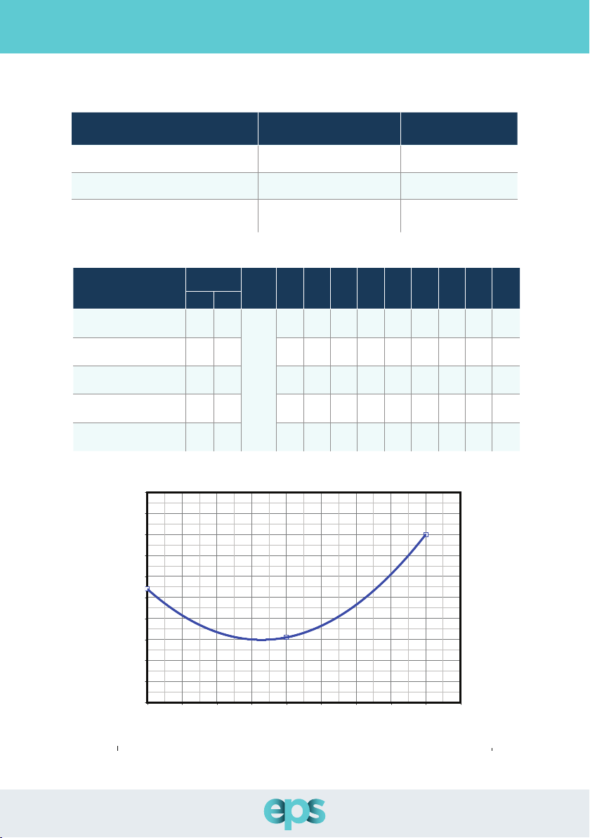
Noise Level of the Multiboost Set
≥48-55dB ≥48-55dB
Pump Type Specications
Pump Type Power Q
l/min 0 10 20 30 40 50 60 70 80
kW HP
Pedrollo Top Multi 2 /
Top Multi Tech
0.55 0.75
H Metres
42
40 38 34 30 24 18 11.5 5
Pedrollo NKm-GE-N 2/3
0.55 0.75 48
46 44.5 42.8 40.5 37.5 33.5 29 23
Pedrollo Upm –GE-N 2/3
0.55 0.75 48
46 44.5 40.5 33.5 23 - - -
Pedrollo NKm –GE-N 2/4
0.75 1 60
58 55 51 47 42 36 30 23
Pedrollo Upm –GE-N 2/4
0.75 1 63
61 59 - 54 - 45 - 31
Pump Type & Control Information
• The declared performances are valid for liquids with density 1,0 kg/dm3and kinematic viscosity 1mm2/s
Date:
Approved by: Enrico Vandin
TOP MULTI 2 50Hz
TEST REPORT EN ISO 9906 Grade 3B
23.09.2015
45
46
47
48
49
50
51
52
53
54
55
0 10 20 30 40 50 60 70 80 90
Flow rate Q (l/min)
dB(A) at 1m
The declared performances are valid for liquids with density 1,0 kg/dm
3
and kinematic viscosity 1 mm
2
/s.
Top Multi 2 dB Level Graph 2015
The declared performances are valid for liquids with density 1,0 kg/dm3and kinematic viscosity 1mm2/s
Please note, when a pump is submerged in liquid, you are no longer dealing with decibel levels, but vibration levels, so the positioning of your
Multiboost is vitally important. The subsequent vibration levels will vary depending on the amount of space surounding the unit and the
type of material it is placed on. The use of insulation jackets will help to reduce vibration noise.

19
19
Pump Type & Control Information
• The declared performances are valid for liquids with density 1,0 kg/dm3and kinematic viscosity 1mm2/s
Conguration Fixed Speed Preso Multiboost
Settable parameters:
Running pressure.
When the pressure in the system
falls below the Pm, PRESFLO®
starts-up the pump. The Pm
should always be higher by at
least 0.2 – 0.3 bar of the pressure
generated by the column of
water overlooking PRESFLO®.
The Pm value can be carried in the
eld between 1 bar and 5 bar.
Maximum current allowed.
PRESFLO® is “tted with a current
sensor, which continually detects
the absorption of the pump. If
the current remains above the set
Imax value for a signi”cant period
of time, PRESFLO® stops the pump
to protect it from damages (LOCK
condition for OVERCURRENT).
PRESFLO® nevertheless allows
the Imax to be exceeded for short
periods during the pump start-up
phase.
For correct functioning, the
Imax should be set at a value
higher by approx. 10 – 20% to
the maximum absorption of the
pump
(normally indicated on the rating
plate of the motor).
If this rating value is not known, it
s better to leave the standard Imax
value (16A) to avoid that the pump
stops also in normal absorption
conditions.
The Imax value may be varied in
the“eld between 4A and 16A.
Manufacturer’s setting:
PRESFLO® is supplied with the following STANDARD CONFIGURA-
TION:
Running pressure
Pm = 2 ( bar )
Max. current allowed
I max = 16 ( A )
Conguration:
The adjustment of the starting pressure (Pm) and the maximum
permissible current (I max) is done by means of two trimmers shown
in FIG.
1. Remove the small screwdriver and adjust the trimmer on the
desired limits, according to the values shown on the plate
located under the screwdriver.
2. The start-up pressure can be adjusted continuously from 1 to 5
bar (trimmer A) .
3. The maximum permissible current can be adjusted continuous-
ly from 4 to 12 A (trimmer B)
4. When you nish adjustment close the cover
Fixed Speed - Presflo Multi Controls
Fixed Speed Control Pressure Settings
The Multiboost discharge cut-in pressure is factory set on the controller. The maximum
discharge pressure setting should not be set higher than the pressure the pump can achieve,
otherwise the pump will not stop with “a no water” demand condition, and will result in heating
the liquid in the pump and possible shaft seal damage.
The cut-in pressure is factory set at 2.5 bar pressure and 4.5 Amps
Pre-charge cut in pressure in the pressure tank must be set 2lbs below the cut in pressure. It is
recommended to check the tank air pressure every 4 months.

20
20
Troubleshooting
Problems Signals Possible causes Solutions
PRESFLO®(Multi)
will not turn on
POWER ON
PUMP ON
No power Check the electrical connections
The pump will
not start when a
tap is turned on
POWER ON
PUMP ON
PRESFLO® model with an inad-
equate start-up pressure (Pm)
for the chosen application
Relocate PRESFLO® to another
position
Install a model with a higher start-up
pressure (Pm)
POWER ON
PUMP ON
Faulty electrical connections
or pump out of service
Check the electrical connections and
that the pump is working
POWER ON
PUMP ON
PRESFLO®“STAND-BY”” Reset PRESFLO® (See Operation,
point 3).
POWER ON
PUMP ON
PRESFLO® in temporary shut
down due to“DRY RUNNING”
due to lack of water
Wait for the automatic restart or
press START to restart manually (See
Operation, point 4a)
Maximum pump pressure is
insucient
Replace the pump with one with
more suitable characteristics
Install a model with a lower start-up
pressure (Pm)
POWER ON
PUMP ON
PRESFLO® in temporary shut
down due to“FREQUENT
START-UP”
Wait for the automatic restart or press
START to restart manually (See Oper-
ation, point 4b). Remove any cause
of leakage from system or install an
expansion tank
POWER ON
PUMP ON
PRESFLO® stops due to“OVER-
CURRENT”
Check if the setting of the maximum
current (Imax) is congruent with the
data of the pumps’ratingplate. If after
manually restarting the pump after
correctly setting PRESFLO®, it again
signals an anomaly, check that the
motor has no mechanical or electrical
problems.
The pump
delivers no or
low pressure
POWER ON
PUMP ON
Filters or pipes may be partly
blocked
Check the water pipes
PRESFLO®’s valve will not open
completely
Check that the valve is not blocked
by any foreign objects and clean if
necessary
The pumps
stops and starts
repeatedly
POWER ON
PUMP ON
POWER ON
PUMP ON
Leaks within the system (less
than the shut-o ow rate Qa)
Check the hydraulic connections and
repair any leaks. If a leak cannot be
repaired, install an expansion tank
The pump will
not stop
POWER ON
PUMP ON
The ow rate is higher than
the shut-o ow rate (Qa)
Make sure that all taps are turned o
and that there are no leaks within
the system
PRESFLO®’s check valve will
not close or is damaged
Check that the valve is not blocked
by any foreign objects and clean if
necessary
On FlashingO
Presflo Multi
Presflo Vario
This manual suits for next models
61
Table of contents
Popular Water Pump manuals by other brands


Goulds Pumps
Goulds Pumps 3935 Installation, operation and maintenance instructions

Adam Pumps
Adam Pumps G FLOW TRANSLATION OF ORIGINAL INSTRUCTIONS

EBARA
EBARA 3D Operating and maintenance manual

Pfeiffer Vacuum
Pfeiffer Vacuum ES 25S operating instructions

Grundfos
Grundfos UPM3 instructions

Graco
Graco Husky 715 instructions

Kessel
Kessel Aqualift F Duo/XXL SPF 550 KE Installation, operating and maintenance instructions

Calpeda
Calpeda CAL170 TECHNICAL INSTRUCTIONS FOR USE

Denso
Denso first time fit instructions

Grundfos
Grundfos alpha2 l Installation and operating instructions

Bestway
Bestway Sidewinder 62097 operating instructions

Grundfos
Grundfos Hydro Multi-B instructions